Equilibrium shape of single-layer hexagonal boron nitride islands on low-index metal substrates
Abstract
Large, high-quality layers of hexagonal boron nitride (hBN) are a prerequisite for further advancement in scientific investigation and technological utilization of this exceptional 2D material. Here we address this demand by investigating chemical vapor deposition synthesis of hBN on an Ir(111) substrate, and focus on the substrate morphology, more specifically mono-atomic steps that are always present on all catalytic surfaces of practical use. From low-energy electron microscopy and atomic force microscopy data, we are able to set up an extended Wulff construction scheme and provide a clear elaboration of different interactions governing the equilibrium shapes of the growing hBN islands that deviate from the idealistic triangular form. Most importantly, intrinsic hBN edge energy and interaction with the iridium step edges are examined separately, revealing in such way the importance of substrate step morphology for the island structure and the overall quality of 2D materials.
Production of single- and multi-layer hexagonal boron nitride (hBN) samples with minimum amount of defects has developed into one of the most important areas of investigation of this insulating 2D material (2DM) exhibiting high chemical stability and excellent thermal conductivity Nagashima et al. (1995); Pakdel et al. (2014); Zhang et al. (2017). Elimination of defects from the production process is essential for scalable, high-throughput synthesis of hBN that holds a great potential for advancements in various fields of technology, such as field effect transistors Roy et al. (2014), light-emitting diodes Ross et al. (2014) and sensors Sajjad et al. (2013). The method enabling such synthesis is chemical vapor deposition (CVD), which in the case of hBN typically consists of initial nucleation of individual islands on a catalyst metal surface, followed by island growth and coalescence to form a full monolayer Kim et al. (2012). When neighboring islands merge, defects are formed at the boundary, resulting in lower material quality and deterioration of device performance Gibb et al. (2013); Li et al. (2015). Since island coalescence is an unavoidable step in CVD synthesis, it is important to understand all aspects of island nucleation, shape, and growth, in order to develop new routes for synthesis optimization.
Single-layer hBN has been grown via CVD on a wide range of single- and poly-crystalline metal substrates, e.g., on Ru, Rh, Ni, Ir, Pd, Pt, Cu and Fe Goriachko et al. (2007); Corso et al. (2004); Auwärter et al. (2003); Lee et al. (2012); Orlando et al. (2012); Morscher et al. (2006); Ćavar et al. (2008); Kim et al. (2012); Joshi et al. (2012); Vinogradov et al. (2012). Initially, hBN islands are often zig-zag (ZZ) terminated triangles, with possible exceptions for some growth conditions Stehle et al. (2015); Poelsema et al. (2019a); Felter et al. (2019). The triangles exhibit two dominant orientations, which originate from the bi-elemental hBN unit cell Auwärter et al. (2003). Further evolution of island shape, and therefore the domain boundaries later on, can be altered during CVD by adjusting the accessible parameters (e.g., temperature or precursor pressure/flux Stehle et al. (2015)), but the choice of a particular substrate with its specific morphology is a crucial initial factor, since precursor-substrate and hBN-substrate interactions dictate the course of the synthesis.
A very important feature of substrate morphology are surface steps. They are always present on both single-crystalline and poly-crystalline foil substrates, and are often sites of hBN nucleation Sutter et al. (2008); Petrović et al. (2017); Farwick zum Hagen et al. (2016). Also, island growth anisotropy induced by the substrate steps has been observed for hBN on Ru(0001) Sutter et al. (2011), Pt(111) Zhang et al. (2015), Ir(111) Petrović et al. (2017), and Cu(110) Wang et al. (2019), and in a similar manner for graphene on metals Sutter et al. (2008); Loginova et al. (2009); Wang et al. (2016). Due to the increased binding of the edge of 2DMs to the substrate step edge, step-up (and in some cases also step-down) growth is hindered and causes anisotropic growth rates of the islands. However, up to now very little attention has been devoted to disentangling the different energy factors that contribute to the observed island shapes. Here, we elucidate the origin of hBN island shape anisotropy on metals by performing a case study of hBN growth on Ir(111) with low-energy electron microscopy (LEEM). We explicitly consider the intrinsic energy of hBN island edges Liu et al. (2011), the islands’ binding to the substrate, and the specifics of the interaction between hBN island and substrate step edges. Such detailed study is feasible because hBN-Ir interaction is weak enough to allow hBN growth over the step edges, but is sufficiently strong Preobrajenski et al. (2007) so that the effects of hBN edge-Ir step edge interaction become clearly visible in experiments in the form of distinct triangular and trapezoidal islands with ZZ edges Petrović et al. (2017).
Single-layer hBN was grown on Ir(111) in an ultra-high vacuum setup via CVD by using borazine as a precursor. The Ir single-crystal was cleaned by Ar sputtering at 2 keV followed by heating in oxygen at 1170 K and annealing at 1470 K. Unless otherwise noted, the borazine pressure during CVD was mbar and the temperature was 1170 K. An Elmitec SPE-LEEM III microscope was used to carry out in-situ, bright field LEEM and selected-area low-energy electron (-LEED) measurements. Atomic force microscope (AFM) measurements were performed ex-situ in air with a Veeco Dimension 3100 microscope operated in tapping mode.
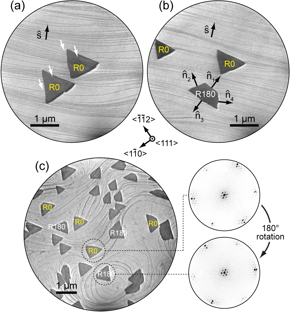
LEEM images in Figs. 1(a) and (b) show isolated hBN islands on the Ir surface, where thin dark lines spanning across the field of view are Ir step edges. Crystallographic analysis, taking into account image rotation in LEEM (e.g., see Ref. Felter et al., 2019 for technical details), reveals that the hBN edges are of ZZ type. The orientation of hBN island edges can be described by unit vectors which are perpendicular to the edges, as shown in Fig. 1(b). The local orientation of Ir steps is designated by a unit vector which for every point along the step is perpendicular to the step. The orientation of , i.e., the difference between step-up and step-down direction, can be determined by recognizing that the short base of the trapezoid must be facing the Ir step-up direction (see AFM data below). When straight steps are present on the Ir surface and shows minor change across a large area, as in Fig. 1(a) and (b), one hBN orientation (denoted as R0) grows exclusively in triangular form, and the other one (rotated by , denoted as R180) grows exclusively in the form of trapezoids, as we reported earlier Petrović et al. (2017). The shape of islands changes, however, when the Ir substrate exhibits a complex surface morphology and contains step edges with large curvature, including hills and valleys. Such a situation is shown in Fig. 1(c), where many R0 and R180 islands are visible (in this particular case, the borazine pressure during synthesis was mbar, leading to a higher island density). Whether the islands are of R0 or R180 orientation can be deduced (i) by simply measuring the orientation of their edges, or (ii) by comparing the islands’ 3-fold symmetric -LEED patterns as illustrated in Fig. 1(c).
A careful inspection of LEEM images reveals that R0 islands are triangular on some parts of the surface, while they are trapezoidal on other parts [see labeled islands in Fig. 1(c)]. Moreover, the short base of trapezoidal islands is found at different positions, i.e., the triangles truncation occurs at different vertices in order to form trapezoids. This is also valid for R180 islands. Considering that the short base of trapezoidal islands faces the step-up direction of Ir, we deduce that R0 and R180 islands are not predetermined to grow as triangles or trapezoids, but their shape is governed by Ir step morphology.
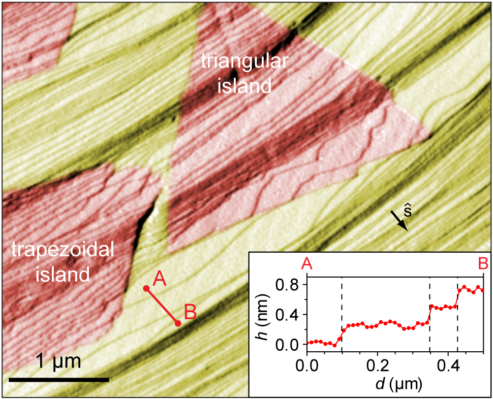
Close to the hBN edges, Ir steps are often strongly bent, as marked by white arrows in Fig. 1(a), indicating that the interaction between hBN island edges and Ir step edges is significant and plays an important role in the growth of hBN. Recently, Poelsema et al. also found that the growth of hBN on Ir(111) results in a severe reorientation of Ir step edges Poelsema et al. (2019b). A better view of step layout can be obtained from scanning probe imaging. In Fig. 2, an AFM image with several hBN islands is shown. The step-up direction is easily identified from an AFM profile shown in the inset. Ir step edges, which are rather straight in the hBN-free region, are distorted in areas where hBN islands overgrew them. This is most prominent at the lower right edge of the triangular island that faces the Ir step-up direction, where Ir steps exhibit a wavy structure and contain straight segments parallel to the hBN edge. Furthermore, in Fig. 2, a short base of the trapezoidal island has formed in the step-up direction, facilitating in such way parallel configuration of hBN edge and Ir steps. Our AFM data suggests that strong hBN-Ir interaction favors attachment of hBN edges to Ir step edges which is enabled by their parallel alignment, most prominently in the step-up direction of Ir.
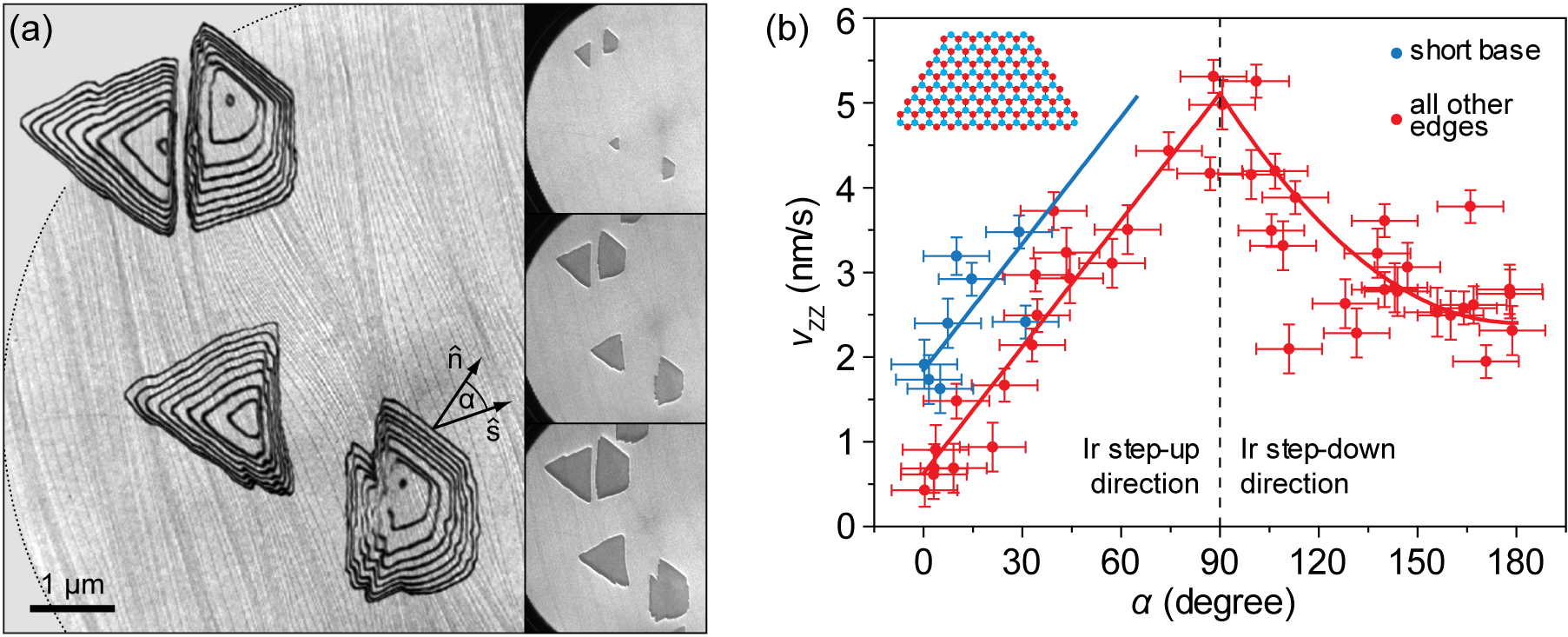
We now proceed to discuss the evolution of the island shape during growth. Contours of several hBN islands extracted from LEEM data are shown in Fig. 3(a), corresponding to the ZZ-type perimeters of R0 and R180 islands recorded at time intervals of 32 s. The island growth is quantified by measuring edge distances from the island nucleation site, , and calculating the average advancement speed as . At the same time, the angle between and has been measured for each edge, thus providing information to plot as a function of . In total, 16 islands have been analyzed, and from the data shown in Fig. 3(b) it is clear that hBN edges propagate faster (slower) when their normals are perpendicular (parallel) to the local direction of . Short bases of trapezoids (blue dots) have been singled out from all other edges (red dots) because of their different elemental composition (see inset). The data in Fig. 3(b) shows functional dependence, and we fit it with simple mathematical functions in order to establish an analytical model of hBN growth. At , the island edge changes its growth orientation from step-up to step-down with respect to the Ir surface, and it is reasonable to assume modification of hBN-Ir interaction and also a different behavior of . Therefore, we fit the data with a combination of linear (for ) and quadratic (for ) functions (see Supporting Section S1 for fit details).
From a comparison of the product , where is the typical island size, with the values of the diffusion coefficient of various borazine fragments, i.e., the building blocks for hBN growth, it is clear that (see Supporting Section S2 for more details). This implies that hBN growth on Ir(111) is taking place near the thermodynamic equilibrium and that is proportional to the edge free energy Artyukhov et al. (2012). In that case, the thermodynamic Wulff construction can be applied to obtain the shape of 2D islands Artyukhov et al. (2012); Zhang et al. (2016), and hence we use it to reconstruct the observed R0 and R180 island forms. We use an analytic expression for the epitaxial hBN island edge energy per unit length as a function of polar angle and chemical potential difference, Zhang et al. (2016); Liu et al. (2011) (see Supporting Section S3 for details). The chemical potential is defined as a disbalance between chemical potentials of B and N atoms, . Highly positive favors B-terminated ZZ edges, while highly negative favors N-terminated ZZ edges. also contains binding energies of ZZ and armchair edges to Ir that can be found in the literature Laskowski et al. (2008); Zhao et al. (2015); Farwick zum Hagen et al. (2016).
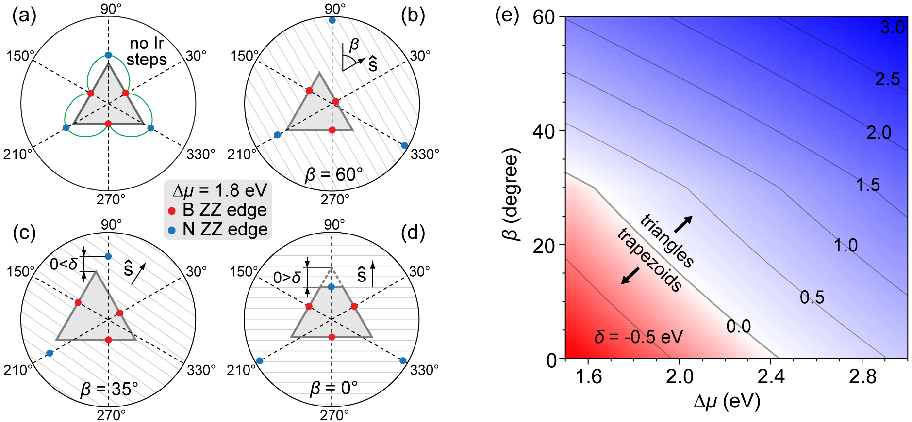
To be consistent with the realistic experimental values of Zhao et al. (2015), and also with the preference of B-terminated ZZ edges Farwick zum Hagen et al. (2016); Petrović et al. (2017), our analysis is restricted to 1.5 eV 3 eV. A comparable analysis with N-terminated island edges, where , is straightforward. The Wulff construction of an hBN island at eV is shown in the polar plot in Fig. 4(a). The edge energy used in this construction includes the hBN island’s intrinsic edge energy and the binding of hBN to the flat Ir substrate without steps (details are given in the Supporting Section S3). The island shape is determined by the red points of which correspond to B-terminated ZZ edges. N-terminated ZZ edges, designated by blue points, have higher energy and therefore do not constitute the edges of hBN island at these conditions. It follows from Fig. 3 and the outlined diffusion considerations that corresponds to the ZZ edge energy modulation arising from the relative edge orientation with respect to the Ir steps. This is incorporated into the Wulff construction by applying and by repositioning the red and the blue points in Figs. 4(b)-(d) accordingly. Our LEEM data shows that these few points are the only relevant ones to describe the shape of hBN islands.
For the sake of clarity, we focus on the top vertex and the upper-right edge of the triangular hBN island in Figs. 4(a)-(d) to examine the truncation effect of the island. Introduction of Ir steps modifies the energies of all hBN edges, depending on the orientation of hBN island with respect to Ir steps. This orientation is quantified by the angle measured between and direction corresponding to [see Fig. 4(b)]. For relatively large values of as in Figs. 4(b) and (c), Ir step-bending as visible in the AFM data of Fig. 2 is the optimal mechanism for hBN island energy minimization. The required bending at the upper-right island edge is not large (step energy increases with the step curvature Giesen (2001)) and its cost is compensated by an overall energy gain achieved by strong binding between parallel hBN edge and Ir steps. In such a situation, B-terminated ZZ edges remain energetically preferred. As decreases, the cost of Ir step bending becomes too high and it becomes energetically non-profitable. However, the energy of N-terminated ZZ edge at the top of the island in Fig. 4(d) is reduced significantly since it becomes (nearly) parallel with Ir steps, resulting in hBN island truncation at the vertex pointing in the step-up direction. After truncation, at the short base of the trapezoidal island, it takes much less (if any) Ir step bending to achieve a parallel configuration and strong binding between hBN island edge and Ir steps, and in such way an initially unfavorable N-termination of hBN islands is energetically compensated.
The presented Wulff construction predicts, in agreement with our LEEM data, that the truncation is allowed only in the Ir step-up direction. It can be argued that in the step-up direction hBN edges become passivated by binding to metal atoms. The result of such an interaction would be a much stronger binding in the step-up direction as compared to the step-down direction, similarly to the case of epitaxial graphene Wang et al. (2016). Binding of different hBN edges to Ir steps that undergo bending and repositioning constitutes the energetic background of , and that is why the inclusion of into the Wulff construction is crucial for obtaining the experimentally observed shapes of hBN islands.
A systematic investigation of the truncation effect is shown in Fig. 4(e) in which , i.e., the vertical separation between N-terminated ZZ edge and its closest vertex as depicted in Figs. 4(c) and (d), is plotted as a function of and . For certain combinations, trapezoidal islands ( red region) are energetically preferred over triangular ones (, blue region). This explains why R0 and R180 islands have different shapes on the surface with uniform , and also why do they change their shape when (i.e., ) changes. The level of truncation of the triangle also depends on and , explaining trapezoids of different heights in Fig. 1(c).
In summary, we have shown that the step morphology of the substrate used in CVD growth of hBN is a crucial factor which determines the energetically most stable shape of synthesized hBN islands. The total energy of the system is minimized by adhering hBN edges to the Ir step edges, which is achieved by repositioning of Ir steps and formation of trapezoids (instead of triangles) during hBN growth. The degree of Ir step repositioning and the feasibility of trapezoidal shape depend on the relative orientation between hBN island edges and Ir steps, and the chemical potentials of B and N atoms during the synthesis of hBN. The use of an extended Wulff construction allowed exact pinpointing of different energy contributions governing hBN growth, and this enables the application of our results, by adjusting the relevant interaction parameters, in studies of hBN synthesis on other metal substrates.
See Supporting information for details of the data fit, evaluation of the diffusion coefficients, and details of .
The Alexander von Humboldt Foundation is acknowledged for financial support. M.P. would like to thank Thomas Michely for stimulating discussions.
References
- Nagashima et al. (1995) A. Nagashima, N. Tejima, Y. Gamou, T. Kawai, and C. Oshima, Phys. Rev. Lett. 75, 3918 (1995).
- Pakdel et al. (2014) A. Pakdel, Y. Bando, and D. Golberg, Chem. Soc. Rev. 43, 934 (2014).
- Zhang et al. (2017) K. Zhang, Y. Feng, F. Wang, Z. Yang, and J. Wang, J. Mater. Chem. C 5, 11992 (2017).
- Roy et al. (2014) T. Roy, M. Tosun, J. S. Kang, A. B. Sachid, S. B. Desai, M. Hettick, C. C. Hu, and A. Javey, ACS Nano 8, 6259 (2014).
- Ross et al. (2014) J. S. Ross, P. Klement, A. M. Jones, N. J. Ghimire, J. Yan, D. G. Mandrus, T. Taniguchi, K. Watanabe, K. Kitamura, W. Yao, D. H. Cobden, and X. Xu, Nat. Nanotechnol. 9, 268 (2014).
- Sajjad et al. (2013) M. Sajjad, G. Morell, and P. Feng, ACS Appl. Mater. Interfaces 5, 5051 (2013).
- Kim et al. (2012) K. K. Kim, A. Hsu, X. Jia, S. M. Kim, Y. Shi, M. Hofmann, D. Nezich, J. F. Rodriguez-Nieva, M. Dresselhaus, T. Palacios, and J. Kong, Nano Lett. 12, 161 (2012).
- Gibb et al. (2013) A. L. Gibb, N. Alem, J.-H. Chen, K. J. Erickson, J. Ciston, A. Gautam, M. Linck, and A. Zettl, J. Am. Chem. Soc. 135, 6758 (2013).
- Li et al. (2015) Q. Li, X. Zou, M. Liu, J. Sun, Y. Gao, Y. Qi, X. Zhou, B. I. Yakobson, Y. Zhang, and Z. Liu, Nano Lett. 15, 5804 (2015).
- Goriachko et al. (2007) A. Goriachko, He, M. Knapp, H. Over, M. Corso, T. Brugger, S. Berner, J. Osterwalder, and T. Greber, Langmuir 23, 2928 (2007).
- Corso et al. (2004) M. Corso, W. Auwärter, M. Muntwiler, A. Tamai, T. Greber, and J. Osterwalder, Science 303, 217 (2004).
- Auwärter et al. (2003) W. Auwärter, M. Muntwiler, J. Osterwalder, and T. Greber, Surf. Sci. 545, L735 (2003).
- Lee et al. (2012) Y.-H. Lee, K.-K. Liu, A.-Y. Lu, C.-Y. Wu, C.-T. Lin, W. Zhang, C.-Y. Su, C.-L. Hsu, T.-W. Lin, K.-H. Wei, Y. Shi, and L.-J. Li, RSC Adv. 2, 111 (2012).
- Orlando et al. (2012) F. Orlando, R. Larciprete, P. Lacovig, I. Boscarato, A. Baraldi, and S. Lizzit, J. Phys. Chem. C 116, 157 (2012).
- Morscher et al. (2006) M. Morscher, M. Corso, T. Greber, and J. Osterwalder, Surf. Sci. 600, 3280 (2006).
- Ćavar et al. (2008) E. Ćavar, R. Westerström, A. Mikkelsen, E. Lundgren, A. Vinogradov, M. L. Ng, A. Preobrajenski, A. Zakharov, and N. Mårtensson, Surf. Sci. 602, 1722 (2008).
- Joshi et al. (2012) S. Joshi, D. Ecija, R. Koitz, M. Iannuzzi, A. P. Seitsonen, J. Hutter, H. Sachdev, S. Vijayaraghavan, F. Bischoff, K. Seufert, J. V. Barth, and W. Auwärter, Nano Lett. 12, 5821 (2012).
- Vinogradov et al. (2012) N. A. Vinogradov, A. A. Zakharov, M. L. Ng, A. Mikkelsen, E. Lundgren, N. Mårtensson, and A. B. Preobrajenski, Langmuir 28, 1775 (2012).
- Stehle et al. (2015) Y. Stehle, H. M. Meyer, R. R. Unocic, M. Kidder, G. Polizos, P. G. Datskos, R. Jackson, S. N. Smirnov, and I. V. Vlassiouk, Chem. Mater. 27, 8041 (2015).
- Poelsema et al. (2019a) B. Poelsema, A. Acun, L. Schouten, F. Derkink, M. Tsvetanova, Z. Zhang, H. J. W. Zandvliet, and A. van Houselt, 2D Materials 6, 035010 (2019a).
- Felter et al. (2019) J. Felter, M. Raths, M. Franke, and C. Kumpf, 2D Materials 6, 045005 (2019).
- Sutter et al. (2008) P. W. Sutter, J.-I. Flege, and E. A. Sutter, Nat. Mater. 7, 406 (2008).
- Petrović et al. (2017) M. Petrović, U. Hagemann, M. Horn-von Hoegen, and F.-J. Meyer zu Heringdorf, Appl. Surf. Sci. 420, 504 (2017).
- Farwick zum Hagen et al. (2016) F. H. Farwick zum Hagen, D. M. Zimmermann, C. C. Silva, C. Schlueter, N. Atodiresei, W. Jolie, A. J. Martínez-Galera, D. Dombrowski, U. A. Schröder, M. Will, P. Lazić, V. Caciuc, S. Blügel, T.-L. Lee, T. Michely, and C. Busse, ACS Nano 10, 11012 (2016).
- Sutter et al. (2011) P. Sutter, J. Lahiri, P. Albrecht, and E. Sutter, ACS Nano 5, 7303 (2011).
- Zhang et al. (2015) Y. Zhang, X. Weng, H. Li, H. Li, M. Wei, J. Xiao, Z. Liu, M. Chen, Q. Fu, and X. Bao, Nano Lett. 15, 3616 (2015).
- Wang et al. (2019) L. Wang, X. Xu, L. Zhang, R. Qiao, M. Wu, Z. Wang, S. Zhang, J. Liang, Z. Zhang, Z. Zhang, W. Chen, X. Xie, J. Zong, Y. Shan, Y. Guo, M. Willinger, H. Wu, Q. Li, W. Wang, P. Gao, S. Wu, Y. Zhang, Y. Jiang, D. Yu, E. Wang, X. Bai, Z.-J. Wang, F. Ding, and K. Liu, Nature 570, 91 (2019).
- Loginova et al. (2009) E. Loginova, N. C. Bartelt, P. J. Feibelman, and K. F. McCarty, New J. Phys. 11, 063046 (2009).
- Wang et al. (2016) Z.-J. Wang, J. Dong, Y. Cui, G. Eres, O. Timpe, Q. Fu, F. Ding, R. Schloegl, and M.-G. Willinger, Nat. Commun. 7, 13256 (2016).
- Liu et al. (2011) Y. Liu, S. Bhowmick, and B. I. Yakobson, Nano Lett. 11, 3113 (2011).
- Preobrajenski et al. (2007) A. Preobrajenski, M. Nesterov, M. L. Ng, A. Vinogradov, and N. Mårtensson, Chem. Phys. Lett. 446, 119 (2007).
- Poelsema et al. (2019b) B. Poelsema, H. J. W. Zandvliet, and A. van Houselt, New Journal of Physics (2019b), 10.1088/1367-2630/ab3dda.
- Artyukhov et al. (2012) V. I. Artyukhov, Y. Liu, and B. I. Yakobson, Proc. Natl. Acad. Sci. U.S.A. 109, 15136 (2012).
- Zhang et al. (2016) Z. Zhang, Y. Liu, Y. Yang, and B. I. Yakobson, Nano Lett. 16, 1398 (2016).
- Laskowski et al. (2008) R. Laskowski, P. Blaha, and K. Schwarz, Phys. Rev. B 78, 045409 (2008).
- Zhao et al. (2015) R. Zhao, F. Li, Z. Liu, Z. Liu, and F. Ding, Phys. Chem. Chem. Phys. 17, 29327 (2015).
- Giesen (2001) M. Giesen, Prog. Surf. Sci. 68, 1 (2001).