Synchrotron radiation from a charge circulating
around a cylinder with negative permittivity
Abstract
We investigate the radiation from a charged particle rotating around a dielectric cylinder with a negative real part of dielectric permittivity. For the general case of frequency dispersion in dielectric permittivity, expressions are derived for the electric and magnetic fields and for the angular density of the radiation intensity on a given harmonic. Compared with the case of a cylinder with positive real part of the permittivity, new interesting features arise in the nonrelativistic limit and for the radiation at small angles with respect to the cylinder axis. Another feature is the appearance of sharp narrow peaks in the angular density of the radiation intensity for large harmonics. We analytically estimate the height, width and the location of these peaks. The influence of the imaginary part of dielectric permittivity on the characteristics of the peaks is discussed. The analytical results are illustrated by numerical examples. We show that the radiation intensity on a given harmonic, integrated over the angles, can be essentially amplified by the presence of the cylinder.
1 Introduction
It is well-known that the presence of medium may essentially enhance the output power of various types of radiation processes. In addition, the polarization of media by charged particles gives rise new types of radiations, such as Cherenkov, diffraction and transition radiations. New interesting features in the radiation processes appear in spectral ranges where the real part of the dielectric permittivity of material becomes negative (for general consideration concerning the existence of a negative dielectric constant see Ref. [1]). The metals provide an example of this kind of material. Due to relatively large densities of free carriers they exhibit a negative permittivity from the visible to microwave frequencies. Another example of material with negative real part of the dielectric permittivity is provided by doped semiconductors [2, 3, 4]. Compared to the metals, the doped semiconductors can exhibit very small losses at infrared and longer wavelengths and the corresponding plasma frequency can be controlled by tuning the free carrier densities.
At interfaces between two media with positive and negative real parts of the dielectric permittivity new types of surface waves arise called surface polaritons. In particular, the surface plasmon polaritons (SPPs) have found a wide range of applications including surface imaging, surface-enhanced Raman spectroscopy, data storage, biosensors, plasmonic waveguides, photovoltaics, various types of light-emitting devices, plasmonic solar cells, etc. Refs. [5]-[8]. SPPs are evanescent electromagnetic waves propagating along a metal-dielectric interface as a result of collective oscillations of electron subsystem coupled to electromagnetic field. Several techniques are available for generation of surface polaritons. In particular, the surface polaritons can be excited by electron beams moving parallel or perpendicularly to the interface (see, for instance, Refs. [9]-[16] and references therein). The radiation of surface polaritons by a charged particle rotating around a cylindrical dielectric waveguide recently has been considered in Ref. [17]. It has been shown that the radiation intensity for surface polaritons of a given harmonic can be essentially larger than that for guiding modes of the cylinder (the radiation on guiding modes for a cylinder with positive dielectric permittivity is investigated in Refs. [18, 19]).
For a charge rotating around a cylindrical rode, in addition to the radiation of surface-type modes (surface polaritons) and guided modes, where will be radiation propagating at large distances from the cylinder. That corresponds to the synchrotron radiation [20, 21] influenced by the presence of the cylinder. For a cylinder with positive dielectric permittivity, in Refs. [22, 23] it has been shown that for the rotation orbit close to the cylinder surface the influence of the cylinder on the angular distribution of the radiation intensity on a given harmonic can be essential. In particular, under the Cherenkov condition for the velocity of the charge image on the cylinder surface and for the cylinder dielectric permittivity, strong narrow peaks may appear in that distribution (similar features for the radiation from a charge circulating around a dielectric ball were discussed in Refs. [24, 25]). The corresponding results for a charge moving along a helical trajectory around a cylinder are presented in Ref. [26, 27]. In the present paper we consider the features for the radiation from a charge rotating around a dielectric cylinder in the frequency range with negative real part of dielectric permittivity of the cylinder material.
The organization of the paper is as follows. In the next section we describe the problem setup and present the electric and magnetic fields in the region outside the cylinder. The spectral-angular distribution of the radiation intensity is investigated in Sect. 3. The features of the radiation are discussed in various asymptotic regions of the parameters. Numerical examples illustrating the general results are presented in Sect. 4. Section 5 concludes the main results of the paper.
2 Problem setup and the electromagnetic fields
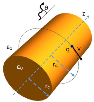
We consider a particle with charge moving along a circular trajectory of radius around a cylinder with radius and with dielectric permittivity . The radii of the particle trajectory and of the cylinder will be denoted by and , respectively, and it will be assumed that the system is embedded in a homogeneous medium with dielectric permittivity . We will consider the general case of frequency dependent complex permittivity . In accordance with the problem symmetry we will use the cylindrical coordinate system with the axis along the cylinder axis (the geometry of the problem is depicted in Fig. 1). For the components of the current density in that coordinates one has
| (1) |
where , is the particle velocity and is the angular velocity.
Here we are interested in the radiation at large distances from the cylinder in the frequency range where the real part of the dielectric permittivity of the cylinder is negative, . We assume that the host medium is transparent and the corresponding dielectric permittivity is real and positive. Under these conditions there are two types of radiations: the radiation propagating at large distances from the cylinder and the radiation of surface-type modes localized near the cylinder surface. For a metallic cylinder the latter corresponds to SPPs, whereas the first type of radiation corresponds to the synchrotron radiation influenced by the cylinder. As it will be shown below, that influence can be essential. The frequency range of negative is also of special interest for the optics of small particles [28]. Among the simplest models describing the dispersion of dielectric permittivity is the generalized Drude model where the conduction electrons are considered as a free-electron gas (see, for instance, Refs. [2, 28]). The corresponding frequency dependence is given by the expression
| (2) |
where is the plasma frequency and is the mean relaxation time of conduction electrons. The part is related to the contribution of bound-electrons and can be described by the Lorentz oscillator model. In some frequency ranges it can be approximated as constant. The plasmonic effects in metals and doped semiconductors are mainly discussed on the base of the model (2). The doped semiconductors with low electron density are used to bring the plasma frequency down to THz range. Another approach is based on the use of appropriately designed metamaterials.
First we consider the electromagnetic fields created by the current density (1). For the corresponding electric, , and magnetic, , fields one has the following Fourier expansion
| (3) |
with and . By taking into account that , where the star means the complex conjugate, in the discussion below for the Fourier components we will assume that . Note that the term in Eq. (3) is time independent and will not contribute to the radiation fields. The Fourier components of the fields can be found by using the Green function from Ref. [22] in a way similar to that presented in Refs. [22, 23, 26] for a cylinder with positive dielectric permittivity and in what follows we will omit the details.
Denoting the cylindrical components as , with , and for simplicity of the presentation omitting the arguments , for the magnetic field in the region one gets
| (4) |
where , , is the Hankel function of the first kind and
| (5) |
The functions are defined by the expression
| (6) |
with and being the Bessel and modified Bessel functions, and
| (7) |
The other notations in Eq. (6) are defined as
| (8) |
and
| (9) |
for the Bessel and Hankel functions . The Fourier components for the electric field are obtained from Eq. (4) by using the Maxwell equation . In the region one gets
| (10) |
where .
The parts in the fields (4) and (10) with the first term in the right-hand side of Eq. (6) do not depend on and correspond to the fields for a charge rotating in a homogeneous medium with permittivity when the cylinder is absent. The corresponding Fourier components will be denoted by , . They are given by expressions which are obtained from Eqs. (4) and (10) making the replacement with
| (11) |
The parts in the fields with the last two terms in Eq. (6) are induced by the cylinder. The expressions for the Fourier components in the region are obtained from Eqs. (4) and (10) making the replacements of the Bessel and Hankel functions in the parts corresponding to the fields in a homogeneous medium. Note that the radial dependence of the Fourier components inside the cylinder is described by the functions and .
The radiation fields at large distances from the cylinder correspond to the integration range in Eq. (3), where , defined by Eq. (5), is real. For the parts with the integration range the quantity is purely imaginary and the fields induced by the cylinder depend on the radial coordinate through the Macdonald functions . These parts are exponentially suppressed at large distances from the cylinder and for a cylinder with a negative real part of they correspond to the surface-type modes. Note that for the surface-type modes the allowed values of are the solutions of the equation . The radiation fields and the radiation intensity for this type of modes have been discussed in Ref. [17]. In what follows we are interested in the radiation at large distances from the cylinder.
3 Spectral and angular distribution of the radiation intensity
Having the electromagnetic fields we can investigate the intensity of the radiation propagating in the exterior medium. As we have mentioned before, for the corresponding Fourier components are exponentially damped for large values , and the radiation is present only under the condition . The average energy flux per unit time through the cylindrical surface of radius , coaxial with the dielectric cylinder, is given by the Poynting vector:
| (12) |
where is the period of the charge rotation and is the unit vector along the radial direction. Substituting the Fourier expansions (3) for the electric and magnetic fields, we obtain
| (13) |
where
| (14) | |||||
and the prime means the derivative with respect to the argument of the function. At large distances, assuming that , we use in Eq. (14) the asymptotic expressions for the Hankel functions for large arguments.
Passing in Eq. (13) to a new integration variable , , in accordance with
the energy flux is presented in the form
| (15) |
where is the solid angle element, and
| (16) |
The angular variable is the angle between the wave vector of the radiated photon and the cylinder axis (axis ). Eq. (15) presents the average power radiated by the charge on a given frequency into a unit solid angle. In Eq. (16), the functions are given by Eq. (6), where now we should take
| (17) |
and
| (18) |
Note that Eq. (16) is valid for a general case of dispersion of the cylinder material with complex permittivity. The expression for the angular density of the radiation intensity from a charge rotating in a homogeneous medium with permittivity (denoted here as ) is obtained from Eq. (16) by the replacement , where is given by Eq. (11). By using the recurrence relations for the Bessel function one gets (see, for instance, Refs. [20, 29])
| (19) |
with the notation . For relativistic particles, , the radiation frequency is determined by the harmonic number and by the radius of the rotation orbit . For of the order of 1 mm and for the harmonics of the order 10, the radiation corresponds to the THz frequency range (for configurations of external fields generating that type of circular motion for electron see, for example, Ref. [30]).
Let us consider the behavior of the radiation intensity in some asymptotic regions of the parameters. For a nonrelativistic charge, assuming that , in Eq. (6) we can use the asymptotic expressions of cylindrical functions for small arguments [31]. To the leading order this gives
| (20) |
where
| (21) |
for and
| (22) |
Here, and are given by the expressions (17) and (18). In the expression for we have kept the next-to-leading order terms in order to consider the behavior of the radiation intensity in the frequency range where is close to and for small values of the imaginary part the leading term in the expansion is small. As seen, for a given , the dominant contribution to the radiation intensity (16) comes from the terms with and we get
| (23) |
with from Eqs. (21) and (22). Compared to the radiation on the main harmonic , the radiation on higher harmonics is suppressed by the factor . The part in Eq. (23) with the first term in the expression under the absolute sign corresponds to the radiation in a homogeneous medium with permittivity .
For positive we can keep the leading order terms and in Eq. (23) . In this case, in the expression under the sign of modulus in eq. (23) the contribution of the term induced by the cylinder is smaller than the one corresponding to the radiation in a homogeneous medium and the radiation intensity behaves as . A new qualitatively different feature arises for negative values of and for small . In this case, under the assumption , we see that for and . Now, the dominant contribution to the radiation intensity (23) comes from the part induced by the cylinder and one has for and .
Now let us consider the radiation intensity for small values of the angle and for fixed values of the other parameters. In this limit, assuming that
| (24) |
for cylinder functions having in their arguments and we use the asymptotic expressions for small arguments. In particular, for the function to the leading order we get
| (25) |
where and . In the limit , the angular density of the radiation intensity tends to zero as for and as for . For small angles , assuming that , in the leading terms (25) we can replace by its real part . In this case, an interesting situation arises for and when the leading term in (25) (with the replacement ) may become zero. For given and , that condition can be considered as an equation for the corresponding value of the ratio . In this case the next-to-leading term should be kept in the asymptotic expansion of over and . Near that specified value of the decay of in the limit is slower.
Another new qualitative feature in the radiation intensity, induced by the cylinder, is the possibility for the appearance of strong narrow peaks for large values of the radiation harmonic at specific values of the angle . For a transparent cylinder with a positive dielectric permittivity, this feature has been discussed in Refs. [23, 26]. Here the characteristics of the peaks will be considered in the frequency range with .
We start the discussion with the case of a transparent cylinder when the imaginary part of can be neglected and is real. The peaks we are going to consider arise under the condition which corresponds to the angular range , where and is the velocity of the charge image on the cylinder surface. In this range, by using the asymptotic expressions for the functions and for (see, for instance, Ref. [31]), we can show that
| (26) |
where , and
| (27) |
As it can be seen from Eqs. (6) and (8), the modified Bessel functions and , , appear in the expression of the radiation intensity in the form of the ratio . For the latter, the asymptotic expression for large values of reads
| (28) |
The mathematical reason for the appearance of the above mentioned peaks is the exponential suppression of the ratio for large .
For the further analysis of the peaks in the angular distribution of the radiation intensity it is convenient to rewrite the function in the form
| (29) |
For large values of and under the condition , we expand Eq. (29) with respect to small ratio with . The leading term is obtained from Eq. (29) by the replacement :
| (30) |
The peaks arise near the angles for which this leading term becomes zero: . Near these angles, keeping the next-to-leading order term one gets
| (31) |
and, hence, for in that range we have .
Now let us estimate the contribution of separate terms in , defined by Eq. (6), for large . The contribution of the first term in the right-hand side of Eq. (6) (corresponding to the radiation in a homogeneous medium) is suppressed by the factor . The contribution of the second term is suppressed by . By taking into account that the function is monotonically decreasing for we have . Consequently, the suppression of the second term is stronger than that for the first one (by the relative factor ). If the angles are not close to the ones determined by the zeros of , the function is of the order of one and the contribution of the third term in the right-hand side of Eq. (6) is of the same order as that for the second term. In this case the contribution of the first term in Eq. (6) dominates and the radiation intensity is close to the one for a charge rotating in a homogeneous medium. The situation is essentially different for the radiation angles close to the ones determined by the zeros of . For these angles one has and the contribution of the last term in Eq. (6) is of the order . Hence, the angular density of the radiation intensity for the peak at is proportional to . For the peak in the region () the height increases with decreasing . The angular width of the peak can be estimated in a way similar to that given in Ref. [26] and is of the order . As seen, with increasing height of the peak the corresponding width decreases. In the next section this features will be illustrated by numerical examples.
4 Numerical examples
In the numerical investigation of the spectral-angular distribution of the radiation intensity at large distances from the cylinder we evaluate the angular density for the number of the quanta radiated on a given harmonic per period of the particle rotation:
| (32) |
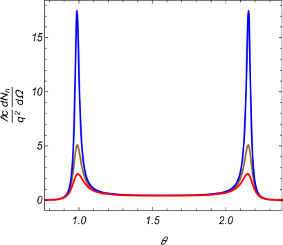
In Fig. 2 we display the dependence of this quantity (in units of ) on the radiation direction for a transparent cylinder () with dielectric permittivity in the vacuum (). The graphs are plotted for , and the numbers near the curves correspond to the values of . For the cases we see the presence of the peaks described above analytically. For the angular locations of the peaks one has for and for . With increasing , the angular location of the peak in the region is shifted to smaller angles. For the solution of the equation in the region one has for and for . As seen, in agreement with the analysis given above, these roots coincide with the locations of the peaks in the radiation intensity with good accuracy.
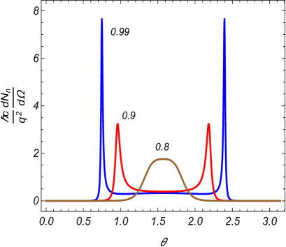
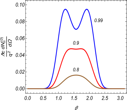
In order to see the effect of the cylinder on the radiation intensity, in Fig. 3 we present the corresponding quantity for the radiation intensity in the absence of cylinder (), (obtained from Eq. (19) in a way similar to Eq. (32)), for the same values of the other parameters. As we see, the presence of the cylinder may lead to an essential increase in the angular density of the radiation intensity.
As it has been explained by the asymptotic analysis, the height of the narrow peaks in the angular distribution of the radiation energy increases with increasing . This feature is seen in Fig. 4, where the angular density of the number of radiated quanta is plotted versus for the harmonic . The values of the other parameters are the same as those for Fig. 2. For the locations of the peaks in the region one has for and for . For the roots of the equation one gets for and for . Again we have a good agreement with the analytical estimates of the locations of the peaks.

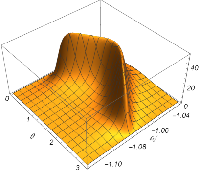
In order to see the dependence of the radiation intensity on the dielectric permittivity of the cylinder, in Figs. 5 and 6 the quantity is plotted as a function of and for , , (Fig. 5) and (Fig. 6). In Fig. 6 we see the formation of angular peaks with increasing . For the peak , , the angle and the width decrease with increasing , whereas the corresponding height increases. This behavior is in agreement with analytical estimates given before.
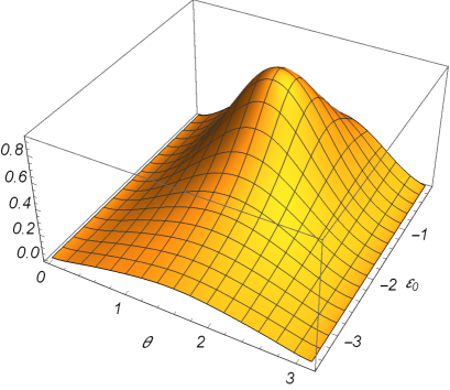

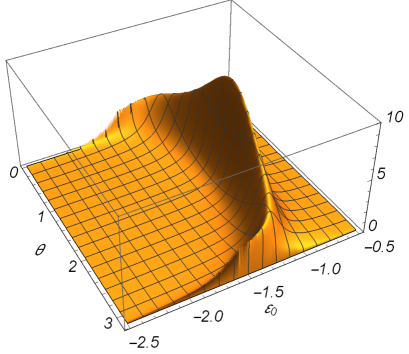
In the discussion above we have argued that for a cylinder with negative dielectric permittivity the behavior of the radiation intensity in the nonrelativistic limit can be essentially different from that in the case of positive permittivity if is sufficiently close to . This feature is seen from Fig. 7, where we have plotted the angular density of the number of the radiated quanta (in units of ) as a function of and for , , .
As it has been mentioned above, the height of the peaks in the angular distribution of the radiation intensity is increasing with increasing harmonic number. However, it should be noted that in realistic physical situation this increase is restricted by several factors. One of them may be taking into account the imaginary part of the dielectric permittivity, . In Fig. 8 we display the angular density as a function of for , , , and for the ratios (with decreasing heights of the peaks). As it is seen from the graphs, the influence of the imaginary part is essential only near the peaks.
In Fig. 9 the angualr density of the radiated quanta number is plotted as a function of and of the real part of the dielectric permittivity for the harmonic and for . The values of the other parameters are the same as those for Fig. 7. Again, we see an essential amplification of the radiation intensity in the region for the values of close to . Compared to the case depicted in Fig. 7, here the region is narrower.
It is also of interest to see the influence of the cylinder on the total radiated energy on a given harmonic, obtained from Eq. (16) by integration over the angles and . Figure 10 presents the total number of the radiated quanta per period of charge rotation, (red circles), versus the number of the harmonic , for and for the same values of the parameters as in Fig. 2. The blue points present the same quantity for the radiation in the vacuum. The corresponding data for are displayed in Fig. 11.
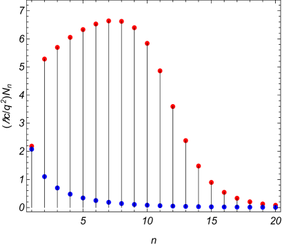
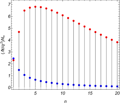
As it is seen from the numerical data in Figs. 10 and 11, the radiation intensity on a given harmonic, integrated over the angles, can be essentially amplified by the presence of the cylinder. For large harmonics, (with the function from Eq. (27)) the radiation intensity tends to the one for the radiation in vacuum. Physically, the latter feature is related to the fact that for those harmonics the Fourier components of the charge field are strongly localized near the particle trajectory and the corresponding polarization of the cylinder is week. The function is monotonically decreasing and with increasing the approaching the radiation intensity to the one in the vacuum is slower for larger .
5 Summary
We have investigated the features of the synchrotron radiation from a charged particle rotating around a cylinder in the spectral range where the real part of the dielectric permittivity is negative. The importance of the investigation of electrodynamical effects in that range is partially motivated by potential applications in plasmonics. In the problem under consideration two types of radiations are present. The first one corresponds to the surface-type modes (surface polaritons) which are localized near the cylinder surface. The corresponding radiation intensity was considered in Ref. [17]. The second type of radiation corresponds to the waves propagating at large distances from the cylinder. The corresponding angular density of the radiation intensity on a given harmonic is given by Eq. (16). Compared to the case of a cylinder with positive dielectric permittivity, a qualitatively new feature appears in the nonrelativistic limit when the real part of the permittivity is sufficiently close to . In this region the angular density of the radiation intensity behaves as for radiation harmonics and like for . For the angular density decays as for . Similar differences from the case of a cylinder with positive dielectric permittivity arise in the behavior of the radiation intensity for small values of the angle .
An interesting feature in the influence of the cylinder on the radiation at large distances from the cylinder is the possibility for the appearance of strong narrow peaks in the angular distribution of the radiation intensity on large harmonics. They are located in the angular region , with being the velocity of the charge image on the cylinder surface. We gave analytic estimates for the location, height and the width of the peaks. With decreasing values of the angle in the range the height of the peak increases, whereas the width decreases. Similar behavior takes place with increasing number of the radiation harmonic. Among the factors that limits the increase of the peak height is the imaginary part of the cylinder dielectric permittivity. The presence of the cylinder may lead also to an essential increase of the integrated intensity of the radiation. All these features we have demonstrated on numerical examples.
Acknowledgement
A.A.S., L.Sh.G. and H.F.Kh. were supported by Grant No. 18T-1C397 from the Science Committee of the Ministry of Education and Science of the Republic of Armenia.
References
- [1] O.V. Dolgov, D.A. Kirzhnits, and E.G. Maksimov, Rev. Mod. Phys. 53, 81 (1981).
- [2] P.R. West, S. Ishii, G.V. Naik, N.K. Emani, V.M. Shalaev, and A. Boltasseva, Laser Photonics Rev. 4, 795 (2010).
- [3] G.V. Naik and A. Boltasseva, Phys. Status Solidi RRL 4, 295 (2010).
- [4] D.M. Mittleman, Nat. Photonics 7, 666 (2013).
- [5] V.M. Agranovich and D.L. Mills (Editors), Surface Polaritons: Electromagnetic Waves at Surfaces and Interfaces (North-Holland Pub. Co., Amsterdam, 1982).
- [6] K. Welford, Optical and Quantum Electronics 23, 1 (1991).
- [7] S.A. Maier, Plasmonics: Fundamentals and Applications (Springer, 2007).
- [8] S. Enoch and N. Bonod (Editors), Plasmonics: From Basics to Advanced Topics (Springer, 2012).
- [9] H. Raether, Surface Plasmons on Smooth and Rough Surfaces and on Gratings (Springer-Verlag, Berlin, 1988).
- [10] F.J.G. de Abajo, Rev. Mod. Phys. 82, 209 (2010).
- [11] M.V. Bashevoy, F. Jonsson, A.V. Krasavin, N.I. Zheludev, Y. Chen, and M.I. Stockman, Nano Lett. 6, 1113 (2006).
- [12] W. Cai, R. Sainidou, J. Xu, A. Polman, and F.J. G. de Abajo, Nano Lett. 9, 1176 (2009).
- [13] J. Zhou, M. Hu, Y. Zhang, P. Zhang, W. Liu, and S. Liu, J. Opt. 13, 035003 (2011).
- [14] S. Liu, P. Zhang, W. Liu, S. Gong, R. Zhong, Y. Zhang, and M. Hu, Phys. Rev. Lett. 109, 153902 (2012).
- [15] S. Liu, C. Zhang, M. Hu, X. Chen, P. Zhang, S. Gong, T. Zhao, and R. Zhong, Appl. Phys. Lett. 104, 201104 (2014).
- [16] S. Gong, M. Hu, R. Zhong, X. Chen, P. Zhang, T. Zhao and Sh. Liu, Optics Express 22, 19253 (2014).
- [17] A.S. Kotanjyan, A. R. Mkrtchyan, A. A. Saharian, and V.Kh. Kotanjyan, Phys. Rev. Accel. Beams. 22, 040701 (2019).
- [18] A.S. Kotanjyan, A.R. Mkrtchyan, A.A. Sahariana, and V.Kh. Kotanjyan, JINST 13, C01016 (2018).
- [19] A.A. Saharian, A.S. Kotanjyan, and V.Kh. Kotanjyan, J. Contemp. Phys. 54, 111 (2019).
- [20] A.A. Sokolov and I.M. Ternov, Radiation from Relativistic Electrons (ATP, New York, 1986).
- [21] A. Hofman, The Physics of Synchrotron Radiation (Cambridge University Press, Cambridge, 2004).
- [22] L.Sh. Grigoryan, A.S. Kotanjyan, and A.A. Saharian, Izv. Nats. Akad. Nauk Arm., Fiz. 30, 239 (1995) (Engl. Transl.: J. Contemp. Phys.).
- [23] A.S. Kotanjyan, H.F. Khachatryan, A.V. Petrosyan, and A.A. Saharian, Izv. Nats. Akad. Nauk Arm., Fiz. 35, 115 (2000) (Engl. Transl.: J. Contemp. Phys.)
- [24] L.Sh. Grigoryan, H.F. Khachatryan, and S.R. Arzumanyan, Izv. Nats. Akad. Nauk Arm., Fiz. 33, 267 (1998) (Engl. Transl.: J. Contemp. Phys.).
- [25] L.Sh. Grigoryan, H.F. Khachatryan, S.R. Arzumanyan, and M.L. Grigoryan, Nucl. Instr. Methods B 252, 50 (2006).
- [26] A.A. Saharian and A.S. Kotanjyan, J. Phys. A 42, 135402 (2009).
- [27] A.S. Kotanjyan and A.A. Saharian, Nucl. Instr. Methods B 309, 177 (2013).
- [28] C.F. Bohren and D.R. Huffman, Absorption and Scattering of Light by Small Particles (John Wiley & Sons, New York, 1983).
- [29] V.P. Zrelov, Cerenkov Radiation in High-Energy Physics (Israel Program for Scientific Translations, Jerusalem, 1970).
- [30] A.A. Saharian, A.S. Kotanjyan, and M.L. Grigoryan, J. Phys. A 40, 1405 (2007).
- [31] Handbook of Mathematical Functions, edited by M. Abramowitz and I. A. Stegun (Dover, New York, 1972).