Cyclic Sequence Generators as Program Counters for High-Speed FPGA-based Processors
Abstract
This paper compares the performance of conventional radix-2 program counters with program counters based on Feedback Shift Registers (FSRs), a class of cyclic sequence generator. FSR counters have constant time scaling with bit-width, , whereas FPGA-based radix-2 counters typically have time-complexity due to the carry-chain. Program counter performance is measured by synthesis of standalone counter circuits, as well as synthesis of three FPGA-based processor designs modified to incorporate FSR program counters. Hybrid counters, combining both an FSR and a radix-2 counter, are presented as a solution to the potential cache-coherency issues of FSR program counters. Results show that high-speed processor designs benefit more from FSR program counters, allowing both greater operating frequency and the use of fewer logic resources.
keywords:
FPGA-Processor , FSR , LFSR , Feedback Shift Register , Cyclic Sequence Generator , Program Counter1 Introduction
A Program Counter (PC) circuit [10] generates the address of the next instruction to be fetched for execution. The greatest contributor to total PC circuit latency in an FPGA-based processor can be due to the counter that is used to increment the current PC value. This is because conventional radix-2 counters implemented within FPGAs can have long carry chains. Pipelining can be used to obtain a higher operating frequency but also increases logic usage, and likely increases the branch penalty.
Non-radix-2 cyclic sequence generators can be used to generate the next instruction address, for example a maximum-cycle Feedback Shift Register (FSR) [5, 13, 6], and can lead to a reduction in total PC latency. This is because FSR counters can be designed where the maximum depth of combinatorial logic required is only one gate [7] therefore the PC latency is constant with bit-width . We explore how this reduction in PC circuit complexity can affect maximum processor operating frequency for three FPGA processor designs.
The sequence of instruction addresses generated by a PC circuit using a maximum-cycle FSR is pseudo-random. For a processor fetching instructions from a small embedded memory this presents no problem. For processors that feature an instruction cache an FSR PC will have poor cache-coherency behaviour. As as solution we present a hybrid PC architecture. The hybid-PC is the concatenation of two smaller counters. The hybrid PC uses a small radix-2 counter to step through instructions within a cache line, and a FSR counter that cycles between cache line. When implemented within FPGA processors, this hybrid approach has low latency and avoids cache-coherency problems.
2 Program Counters
Stan et al. [14] list the properties of generic up/down-counters
but not all of these properties are required for PC circuits. A program counter
must be RESETable, increment once every clock cycle as long as an
ENABLE line is asserted, and sometimes has its value changed by branch
instructions (so it needs to be LOADable, and have IN lines). The
value also needs to be readable every clock cycle (using the OUT lines) in
order to access the memory address to fetch the next instruction. There is no
need to support other common counter features [14], such as being
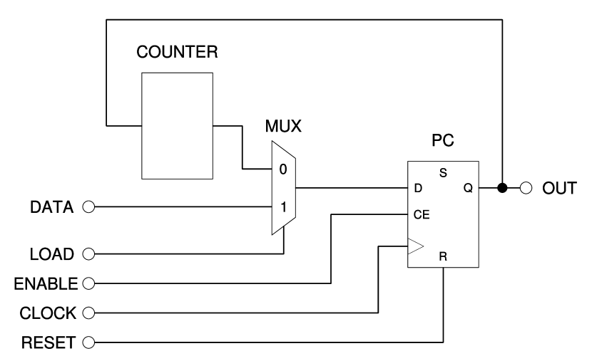
reversible, or any terminal count operations. A black box diagram for a generic
PC circuit is shown in Figure 1.

3 Formal framework for counters
In order to investigate structures that can be used for program counters, it is worth setting up some formalism.
A conventionial radix-2 counter can take on a range of values from 0 to where is the number of bits. The next value of the counter is obtained by incrementing the current value using radix-2 arithmetic. We will show there is a isomorphism between this counter architecture and a family of other counter architectures. We consider only finite counters, as all counters implemented in digital logic will have a finite number of states.
We will start by defining a counter as finite and closed. Closed is not necessary for a program counter (all we need is a sufficent sequence of states to put the program in), but give us some nice properties.
We will then set up a ‘ordinary’ counter which is a cycle of length . We will use isomorphism to this.
Lemma 3.1 is a useful grab bag of properties. Note that from Lemma 3.1(4,5), any state can be used as a generator.
Lemma 3.4 states that all -cyclic counters are isomorphic to (no suprises).
Corollary 3.6 states that all counters have a -cyclic subcounter form some . Just find the limit cycle. Note that the limit cycle may have only one element in it.
The central theorem is Theorem 3.7, that all counters have a sub-counter that is isomorphic to for some . This ties these new counters to counters with known behaviour.
Theorem 3.8 lets us join counters together to form hybrid counters.
-
Definition
Consider a finite set of states and an increment operator . For the purposes of this paper we define a counter as a pair with the following property:
(1)
This (closure) is one of Peano’s axioms for the natural numbers [15] – we don’t need the other four axioms for our purposes.
A useful special case is a modulo arithmetic counter, with the ordinary increment operator.
-
Definition
Let be the counter where .
The conventional radix-2 counter with bits is now simply .
-
Definition
We also define as successive applications of , so
(2) (3)
-
Definition
Given a counter , is a subcounter of if is a counter and .
-
Definition
A counter is -cyclic if , , and . is a generator for the counter.
Lemma 3.1
Given an -cyclic counter , then for any element
-
1.
,
-
2.
for ,
-
3.
,
-
4.
,
-
5.
.
-
Proof
For (1), and . If , . If , we know that , so choose such that . , so .
For (2), assume the contrary. If for some , then consider the set of states . For any , for some . If , then . If , . Hence is closed under . However and , so . However, is closed under , so , contradicting (1). Hence for .
For (3), If for some (assuming w.l.o.g. that ), then where , which violates (2).
For (4), where are elements of and from (3) these values are distinct, so . so (since { is closed) hence . Also, , so .
For (5), we use (4) to give for some . Now . If then (2) is contradicted, and , so and . Hence .
Lemma 3.2
is -cyclic.
-
Proof
Just let . , and .
Lemma 3.3
If , then is -cyclic iff is -cyclic.
-
Proof
Assume is -cyclic. so there exists a mapping such that that is bijective. If , , hence it can easily be seen by induction that .
(from the bijection of ). Given , then , since is bijective. (from the definition of -cyclic), so .
If is -cyclic, the proof that is -cyclic follows from using the same argument with .
Lemma 3.4
A counter is -cyclic iff it is isomorphic to . In particular, if is -cyclic, as is an isomorphism for any .
-
Proof
Firstly we show that of a counter -cyclic, then it is is isomorphic to . We construct an a mapping and show it is an isomorphism. Given an -cyclic counter , pick any element . Define the mapping as . Given any such that , there are two cases. If then . If then . Hence is a homomorphism as shown in Figure 3. From lemma 3.1(3) is an injection, and from lemma 3.1(4) is a surjection, hence is an isomorphism, and .
Theorem 3.5 (Generator)
Given a counter , and an integer such that for and , then is an -cyclic subcounter of .
-
Proof
Let . First we show that , is a subcounter of . Consider any element . for some . . If then , so . If , , so equation 1 is satisfied, making a counter. It is a subcounter of because .
We need to show that the cardinality of . Clearly by the construction. If , then there would be at least one repeated state, so . Assume w.l.o.g that . Now . which for , so .
Consider any . Let , so . Now . So .
Putting this together, , , and , so is an -cyclic subcounter of .
-
Remark
It is worth noting (although we do not use or prove the result) that any element of an -cyclic counter can be used to generate the counter in this way.
Corollary 3.6
All counters have an -cyclic subcounter for some .
-
Proof
This can be done by construction. Consider any counter . is defined to be finite, so let be the cardinality of . Now pick any element and define a sequence . Because of equation 1, all members of this sequence are elements of , and the sequence has members. Therefore there must be at least one value that occurs more than once in this sequence, so we can find two integers and such that where w.l.o.g. and for all such that (if there was such a we could choose instead of for the second value).
Let . , so by theorem3.5, is an -cyclic subcounter of where .
Theorem 3.7
All counters have a sub-counter that is isomorphic to for some .
-
Definition
Given two counters , and an element , we define as the structure where
(4)
is clearly a counter, as equation 1 is satisfied trivially.
Theorem 3.8
If is an -cyclic counter and is an -cyclic counter, then for any is an -cyclic counter.
-
Proof
We construct a mapping in as and as for some . These are isomorphisms from lemma 3.4. Now consider , and a map defined as . , and (since ), so . Hence is a homomorphism from to . It is also clearly a bijection and a surjection, hence an isomorphism. …
There is one operation other than increment that may be performed on a Program Counter - the LOAD operation (RESET is simply a special case of this). There are two forms of LOAD that are currently used:
A program might perform an absolute jump (or LOAD). This simply loads the counter with a new value that has been calculated when the program is created, and is of no difficulty for any sort of counter.
The other form, which is worth examining in some detail, is where the new address is calculated as some offset from the current one by ‘adding’ it to the current value of the program counter. Our system doesn’t have addition defined, so we define one:
-
Definition
Given an counter , and an integer then .
In the case of , , where ‘plus’ is the usual defintion of modulo addition.
4 Radix-2 Counters
Synchronous radix-2 counters are conventionally used for Program Counters, however there is a trade-off between speed and size because of carry propagation from low-order to higher-order bits [14].
The simplest radix-2 counter is a ripple-carry counter based on an adder [14]. This is slow ( combinatorial delay with increasing bit-width ) but cheap in logic (). Xilinx FPGAs use carry-chains to provide the logic for this. This can be improved to combinatorial delay using a carry-lookahead design [9] at the expense of extra logic.
An approach that allows increment in constant time is a redundant format [8] which allows what is called ‘carry-free’ addition, but that has two issues. A redundant representation needs twice as many latches and therefore consumes more FPGA resources. Another problem is that a redundant output is unsuitable for providing an address to access instructions. The output first needs to be converted to a non-redundant format during each clock cycle, which is going to require propagation delay and extra logic for an adder. Some work has been done using hybrid redundant number systems [11] to reduce the number of extra registers, but there is still a substantial propagation delay converting that to a usable format.
Another approach to designing an delay counter is to use a
cascade [9] that begins with a short and fast counter, and
continues with longer counters that only need to be incremented occasionally and
don’t need to be as fast. However, this requires the slower counters to have
their increments to be precomputed [14] which makes the LOAD
operation much more difficult.
4.1 Cyclic Sequence Generators
A cyclic sequence generator is a synchronous circuit that iterates through a cyclic sequence of states. For a program counter, it is desirable to have a simple circuit and a cyclic sequence that includes most of the possible states. A good candidate for this is a maximum cycle feedback shift register.
A Feedback Shift Register (FSR) is a shift register that satisfies the condition that the current state is generated by a linear function of its previous state. There are many types of these, but the ones considered here are linear (use XOR gates), and have a constant maximum combinatorial path, therefore constant time performance () with increasing bit width (see Figure 4 for some examples of these). This compares favourably with radix-2 counters as described in Section 4. A well-known example of an FSR is a Linear Feedback Shift Register [5, 6] (LFSR) that are widely used in cryptography [6], communications systems [12] and for built-in self-test systems [1]. A few of the types of FSR are:
| (a) |

|
| (b) |
|
| (c) |

|
| (d) |
|
- Fibonacci LFSR
-
takes the output of several of the registers and XORs them together to feed to the input of the first register as shown in Figure 4a.
- Galois LFSR
-
takes the output of the last register and XORs it with several of the register inputs as shown in Figure 4b.
- Ring Generators [7]
-
rearrange the shift register into a ring, and arranges the feedback connections so that they only involve a small amount of routing, as shown in Figure 4c.
- MFSR [19]
-
(Multiple Feedback Shift Register) are a generalisation of ring generators, allowing any output to be XORed with any input, but limits the fan-in and fan-out to 2, as shown in Figure 4d.
Also worth considering are cellular automata [3]. These are not Feedback Shift Registers but have similar properties. A cellular automaton has each bit set from the XOR of the previous value of that bit and neighbouring bits, which require more XOR gates than FSRs but keeps the routing very local.
An -stage linear FSR is maximum-cycle when all non-zero states occur as the FSR is iterated. Note that a cycle of cannot be achieved as the all zero state will always map to the all zero state. Any linear FSR can be represented as an matrix over the field , and this will be maximum cycle if and only of the characteristic polynomial is primitive. Lists of primitive characteristic polynomials and counters with maximum cycles can easily be found [6, 2, 18] or generated.
All these structures are very fast, as described above, and have a relatively small amount of logic ( which will mostly be the registers to store the bits), and a pseudo-random sequence. They will have similar performance, due to all having a maximum combinatorial part of just one XOR gate (In Fibonacci this may be 4 gates, but this is still only one LUT on an FPGA). Slight variations in performance may depend on required LUTs and routing in any particular FPGA technology choice and application. The worst case number of XOR gates, fan in and fan out is shown in Table 1. As the sequence is pseudo-random, the bits may also reordered to search for small routing improvements.
FSR counters meet the counter requirements for PC circuit described in Section 2. They are easily loadable, support an enable, and the register can be read directly. One disadvantage to using FSRs is that the maximal cycle size is , instead of the cycle of radix-2 counters. We refer to the address not generated in the cycle as the “zero address”. While the zero address does not represent a significant fraction of the address space, this can be addressed with extra logic as used by Wang and McCluskey [17], but this brings the propagation delay back to .
For the rest of this work we use MFSR counters. They have good fan-in, fan-out, and a low gate count. Other FSRs could be used and would have very similar results (see Figure 4).
| Structure | XOR gates | Fan-in | Fan-out |
|---|---|---|---|
| Fibonacci LFSR | 1 | 4 | 2 |
| Galois LFSR | 3 | 2 | 4 |
| Ring Generator | 3 | 2 | 2 |
| MFSR | 2 | 2 | 2 |
| Cellular Automata | 3 | 3 |
4.2 Hybrid PCs
The instruction fetch order of FSR PCs may lead to poor run-time performance for processor designs that contain an instruction cache. It is desirable to have a PC that increments through all of the instructions within a cache line before fetching a new cache line. For a cache line-size of 32 bytes, and a fixed instruction-width of 32 bits, there will be eight instructions within a cache line. Ideally, and in the absence of branching instructions, each of these eight instructions should be fetched from the cache before fetching another cache line from system memory.
The solution presented here is to combine two counters into one PC, a radix-2 counter for the three least-significant bits and a MFSR for the most-significant bits. Since the Spartan-3 contains four-input Look-Up Tables (LUTs), and the Virtex-5 has six input LUTs, a 3-bit radix-2 counter can be built with just one layer of logic. When the upper count value is reached, the MFSR portion of the PC is then incremented.
5 FPGA Synthesis of Simple Counter Circuits
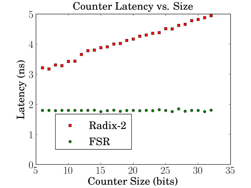
Performance of the synthesised radix-2 and FSR counters are shown in Figure 5. As the bit-width increases radix-2 counters show a linear increase in latency, this is time-complexity. The results show that for radix-2 counters of more than 6 bits, latency can be estimated as ns. The FSR counters have time complexity and a smaller constant of only ns, compared with the radix-2 counters.
6 FPGA Synthesis of Complete PC Circuits
A simple PC circuit was used when investigating the effect of counter-type on PC performance. Figure 6 is a block diagram of the circuit used for testing and the counter used was one of FSR, radix-2, or a hybrid where the lowest 3 bits are radix-2. Bit widths ranging from 8 to 32 bits were used.
6.1 PC Circuit Results
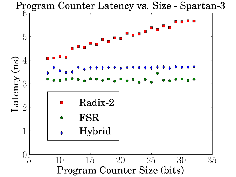
The results of the PC circuit synthesis are shown in Figure 7. As with the previous counter tests, the radix-2 circuits scale linearly with increasing bit-width. Again though, the latencies of FSR-based circuits are lower than radix-2 and both the FSR and hybrid PCs have scaling with increasing bit-width. Due to the Xilinx synthesiser using the carry-chain logic for the radix-2 counters, and FSRs having a gate depth of just one, this is as expected.
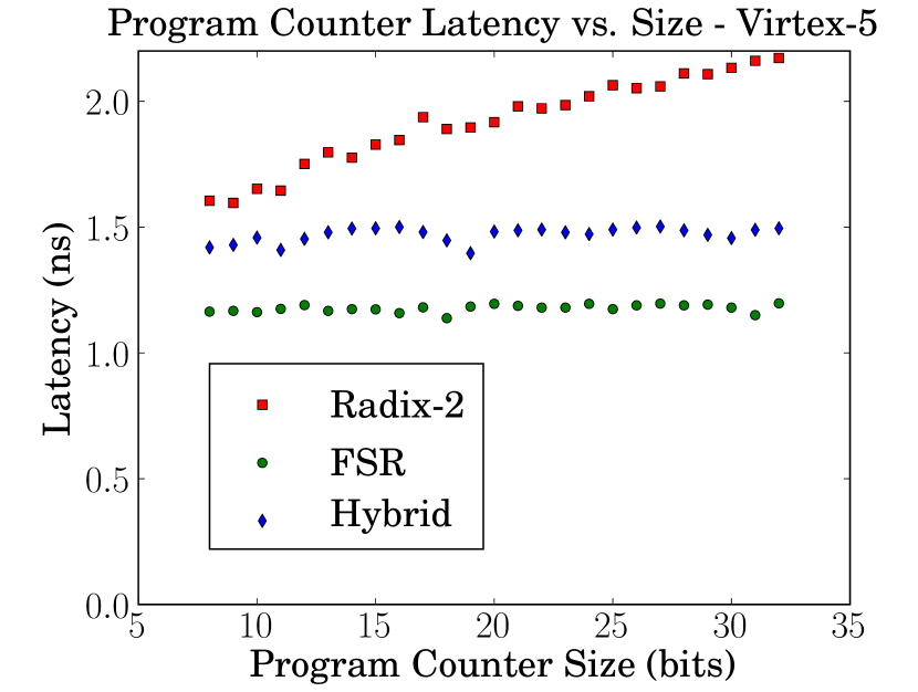
To demonstrate that the behaviour observed when synthesising for a Spartan-3 FPGA is not unique, Figure 8 also shows synthesis results for a Xilinx Virtex-5 FPGA. The latency scaling with increasing bit-width is similar but the Virtex-5 is clearly a faster architecture.
7 Processor Design Examples
Three FPGA processors were synthesised and evaluated to show the effects of different PC circuits on maximum clock frequency. The three processor logic cores used are aeMB, TTA16, and RISC16. aeMB was designed to use a conventional radix-2 PC whereas RISC16 and TTA16 were designed to use a PC circuit based on either a FSR or radix-2 counter.
This is to examine if substituting a FSR-based PC into an existing processor design leads to any performance gains of the processor as a whole, and if there is a detrimental effect of adding a radix-2-based PC to a processor designed for a FSR-based PC. A Xilinx Spartan-3 FPGA was again the synthesis target and Xilinx ISE 9.2 was the synthesis tool.
7.1 aeMB: A MicroBlaze Compatible RISC Processor
The aeMB processor logic core is 32-bit, Harvard architecture, RISC processor with a three-stage pipeline. It is an open source project that was designed to be instruction compatible with the MicroBlaze core [20]. When the aeMB processor core was synthesised for a Spartan-3 FPGA it used about 2600 logic elements.
The critical path of aeMB, as determined from the Xilinx place-and-route timing report, is the instruction-cache look-up path. Total routing resources used were 515643 paths with the original radix-2 PC. The source code was modified, substituting a FSR PC for the radix-2 PC, and resynthesised. This was a straight PC-logic substitution and did not address any potential problems with relative branching and cache coherency.
Maximum operating frequency increased slightly, as is shown in Table 2, logic resource utilisation was similar, but the FSR degign used only 503608 paths. This is a large change in pathing resources used for a small change to the total degign. This large difference in pathing resources, caused only by the change to the PC circuit, was not observed with the other processor cores.
| CPU | PC Size | FSR | Radix-2 | Pipeline |
|---|---|---|---|---|
| (Name) | (Bits) | (MHz) | (MHz) | Stages |
| TTA16 | 10 | 192 | 157 | 3 |
| RISC16 | 10 | 143 | 141 | 5 |
| aeMB | 30 | 84 | 80 | 3 |
7.2 TTA16
TTA16 is a 16-bit, Transport Triggered Architecture [4] (TTA) processor optimised for Xilinx Spartan-3 FPGAs. It is an open-source, Harvard architecture processor and was designed for the high-throughput, data-processing tasks of the Open Video Graphics Adapter (OpenVGA) project [16]. TTA processors have very simple instruction word formats and require only very simple instruction decoders resulting in smaller processor cores. The TTA16 PC circuit is similar to that shown in Figure 6 and contains source code for both types of PC, FSR or radix-2, and can be synthesised with either one.
TTA16 was the processor that showed the greatest frequency improvement with an FSR PC (see Table 2), the FSR counter has 22% greater clock frequency than with the radix-2 counter. TTA16 configured to use the FSR PC is substantially faster than with the radix-2 PC because TTA16 was designed to use a low-latency PC circuit. When TTA16 is synthesised with a radix-2 counter the PC circuit becomes the critical path limiting maximum frequency. We speculate that adding an additional pipeline stage to the radix-2 PC circuit may improve maximum processor frequency, but this would also increase branch latency and FPGA resources required.
7.3 RISC16: A Small 16-bit RISC Processor
RISC16 was also designed for OpenVGA [16], for comparison with TTA16, and shares many design elements. The RISC16 core is has five pipeline stages arranged so that each has similar latency. Decreasing the latency of one small component, the PC circuit, would not be expected to have a big effect on overall performance. Table 2 shows that there were no substantial difference between the FSR and radix-2 PC implementations of the RISC16 processor core.
8 Discussion
Radix-2 counters are the conventional counters used for the processors PC. These have been studied and used extensively. Memories, including caches, often support linear, burst transfers assuming a radix-2 count order. Current software tools, like assemblers and compilers, assume a radix-2 count order as well. FPGAs, like the Xilinx Spartan-3 and Virtex-5 families, contain carry-chains to support radix-2 counters as well.
Traditional assemblers will generate object code suitable only for the radix-2 PC increment sequence. For processors with FSR-based PCs, an assembler is needed that will use a description of the FSR to correctly re-order the processor instruction. An assembler was developed for this purpose and reads an XML-encoded complete processor description prior to generating the assembly output. The assembler supports FSR and radix-2, as well as hybrid PCs consisting of a concatenation of an arbitrary number of FSR and radix2 counters. For each FSR counter used the tap sequence describing the FSR is also encoded within the processor description file.
8.1 FSR Program Counters
The FSR counters are very fast (see Figure 6) leading to a substantially lower-latency PC circuit (see Figure 5). This in turn leads to notable gains in maximum processor operating frequency for the processor with the highest operating frequency, TTA16 (see Table 2). Because a maximal-cycle FSR count cycle is different from a radix-2 counter this has effects on tools, instruction encoding, and cache coherency.
8.1.1 Relative Instruction Addressing
The instruction set of many processors contain branch instructions that store an offset that is added to the current value of the PC. These instructions are called PC-relative branch instructions. When the offset is encoded with a bit-width narrower than the PC, this branching is difficult to do with FSRs.
PC-relative branching with small offsets is widely used in contemporary processors [10] as it allows a subset of addresses, those that are close to the current instruction, to be encoded within an instruction. The simplest approach with FSR-based PCs is to not support PC relative branching. This problem is more easily resolved using Hybrid PCs (see Section 8.2).
8.1.2 Cache Coherency
For processor designs featuring an instruction cache, a FSR-based PC will lead to poor performance. A single FSR-based PC circuit will traverse program memory in a pseudo-random count cycle. Caches are typically designed to fetch multiple words from sequential adresses, called cache lines. A FSR PC circuit may only execute one instruction from this cache line, and then the cache may need to fetch another. A solution to this problem is introduced in Section 4.2 and then issues are discussed in Section 8.2.
8.2 Hybrid Program Counters
The synthesis results, shown in Figures 7 and 8, for the hybrid PCs described in Section 4.2 show that performance is greater than radix-2 PCs at all tested bit-widths. They are therefore a good solution to the cache coherency problems of FSRs. Figures 7 and 8 show that hybrid PCs have only slightly higher latency than pure FSR PCs and with the same constant-latency behaviour with increasing . Hybrid PCs can also be used to solve problems with relative branching and position independent code, though this is future work.
With a hybrid-PC, the FSR portion will not increment when its value is zero, so there is one entire cache line which will not be accessed by the count cycle. This need not be a disadvantage because the first cache line could be used to store other information, for example the interrupt vector table.
9 Conclusions
We have designed PC circuits that can allow some FPGA-based processors to operate at higher frequencies. This is because FSR-based counters have very low latency, a depth of just one logic gate, and PC circuits utilising FSRs can have substantially lower latency when implemented in FPGAs. Due to the constant-time behaviour, with increasing bit-width , FSR counters have an even greater advantage, relative to radix-2 counters, when is large.
For small embedded FPGA processors executing instructions stored in local SRAMs, the pseudo-random count cycle of FSRs is no significant problem either as long as the user has the necessary tools to generate code. We have also presented hybrid PCs to solve the FSR cache-coherency issues for processors that use an instruction cache to reduce average latency for instruction fetching.
9.1 Future Work
There can be many possible maximal-cycle FSRs for a particular bit-width. Some FSRs, due to each having a slightly different circuit, may be faster for a specific implementation than other FSRs. Testing was not performed to find the fastest available FSR circuit for a particular implementation. A future project might be searching amongst the many possible FSRs to find the lowest latency circuit.
Modern compilers can generate position independent code making use of relative branching that is not practicable with a pure FSR-based PC. Further work exploring hybrid program counters, consisting of three or more smaller counters, could probably be used to solve the FSR relative addressing problems.
The emphasis of this work is on FPGA-based processors. Due to their very low gate depth and reduced logic complexity FSR and FSR-radix-2 hybrid PCs may also prove useful with some very low gate-count, or very high clock frequency processors realised in Silicon.
References
- [1] V.D. Agrawal, C.R. Kime, and K.K. Saluja. A Tutorial on Built-in Self-Test. I. Principles. IEEE Design & Test, 10(1):73–82, 1993.
- [2] Peter Alfke. Application Note: Efficient Shift Registers, LFSR Counters, and Long Pseudo- Random Sequence Generators. Technical report, Xilinx Inc., San Jose, CA, 1996. App. note XApp052.
- [3] T. Chang, I. Song, J. Bae, and K.S. Kim. Maximum length cellular automaton sequences and its application. Signal Processing, 56(2):199–203, 1997.
- [4] H. Corporaal. Transport triggered architectures examined for general purpose applications. In Sixth Workshop on Computer Systems, pages 55–71, 1994.
- [5] S.W Golomb. Shift Register Sequences. Aegean Park Press, Laguna Hills, CA, USA, 1981.
- [6] A. Menezes, P. van Oorschot, and S. Vanstone. Handbook of Applied Cryptography. CRC Press, Boca Raton, 1997.
- [7] G. Mrugalski, N. Mukherjee, J. Rajski, and J. Tyszer. High Performance Dense Ring Generators. IEEE Transactions on Computers, pages 83–87, 2006.
- [8] B. Parhami. Systolic up/down counters with zero and sign detection. In Proc. Symp. Comput. Arithmetic, pages 174–178, 1987.
- [9] B. Parhami. Computer arithmetic. Oxford University Press, 2000.
- [10] B. Parhami. Computer Architecture: From Microprocessors to Supercomputers (Oxford Series in Electrical and Computer Engineering). Oxford University Press, Inc. New York, NY, USA, 2005.
- [11] DS Phatak and I. Koren. Hybrid signed-digit number systems: a unified framework forredundant number representations with bounded carry propagation chains. IEEE Transactions on computers, 43(8):880–891, 1994.
- [12] R. Pickholtz, D. Schilling, and L. Milstein. Theory of Spread-Spectrum Communications–A Tutorial. Communications, IEEE Transactions on [legacy, pre-1988], 30(5 Part 2):855–884, 1982.
- [13] M.J.B. Robshaw. Stream Ciphers. RSA Labratories, 25, 1995.
- [14] M.R. Stan, A.F. Tenca, and M.D. Ercegovac. Long and Fast Up/Down Counters. IEEE Transactions on Computers, 47(7):722–735, 1998.
- [15] R.R. Stoll. Set theory and Logic. W H Freeman, 1963.
- [16] P. Suggate. OpenVGA: An Open-Source PCI Graphics Adapter. Master’s thesis, University of Otago, 2009.
- [17] L.T. Wang and E.J. McCluskey. Hybrid designs generating maximum-length sequences. Computer-Aided Design of Integrated Circuits and Systems, IEEE Transactions on, 7(1):91–99, 1988.
- [18] R. W. Ward and T.C.A. Molteno. Table of multiple feedback shift registers. Technical Report 2009-1, University of Otago, 2009.
- [19] Roy W. Ward and T.C.A. Molteno. Counter Representations in Microprocessors. In ENZCon06 Conference Precedings. ENZCon, 2006.
- [20] Xilinx Inc. Microblaze processor reference guide, 2008.