Tibial Implant Fixation in TKA Worth A Revision?
– How to Avoid Stress-Shielding
Even for Stiff Metallic Implants
B. Eidel, A. Gote, C.-P. Fritzen, A. Ohrndorf, H.-J. Christ
Heisenberg-Group, Institut für Mechanik
University Siegen, 57068 Siegen, Paul-Bonatz-Str. 9-11, Germany
∗e-mail: bernhard.eidel@uni-siegen.de
Institut für Mechanik
Universität Siegen, 57068 Siegen, Paul-Bonatz-Str. 9-11, Germany
Institut für Werkstofftechnik
Universität Siegen, 57068 Siegen, Paul-Bonatz-Str. 9-11, Germany
Highlights
-
•
Force decomposition into plate and stem parts is an indicator for post-surgery tibial bone loss.
-
•
Force transfer mainly through the tibial plate (stem) reduces (increases) stress-shielding.
-
•
Strong activation of the plate in force transfer by sliding friction at the stem-bone interface.
-
•
Stress-shielding can be overcome even for stiff metallic implants.
Abstract
In total knee arthroplasty (TKA) force is transmitted into the tibia by a combined plate-stem device along with cemented or cementless stem fixation. The present work analyzes this force transmission in finite element simulations with the main aim to avoid reported postsurgical bone density reduction as a consequence of a reduced tibial bone loading. In the numerical analysis different implant materials, stem/extension lengths and implant-to-stem interface conditions are considered, from a stiff fully cemented fixation to sliding contact conditions with a low friction coefficient. The impact of these variations on bone loading changes are measured by (i) decomposing the total force into parts mediated by the plate and by the stem and by (ii) post-surgery strain energy density (SED) deviations. Based on a bionics-inspired perspective on how nature in pre-operative conditions carries out force transfer from the knee joint into the tibia, a modified implant-bone interface is suggested that alters force transmission towards physiological conditions while preserving the geometries of the standard plate-stem endoprosthesis design. The key aspect is that the axial force is predominantly transmitted through the plate into proximal bone which requires a compliant bone-stem interface as realized by sliding friction conditions at a low friction coefficient. These interface conditions avoid stress shielding almost completely, preserve pre-surgery bone loading such that bone resorption is not likely to occur.
Keywords: Total knee arthroplasty; Stress shielding; Tibia; Implant-bone interface; Finite element analysis
26.09.2020 accepted for publication in Computer Methods in Biomechanics and Biomedical Engineering
The finally published version can show minor differences to the present preprint.
1 Introduction
Total knee arthroplasty (TKA) has evolved into a mature surgical intervention and the number of patients undergoing TKA has considerably increased in the last decades. In the United States for example, the number of TKA performed each year has increased from 31.2 per 100 000 person-years during the period 1971–1976 to 220.9 during the period 2005–2008. In 2012, more than 670,000 total knee replacements were performed in the United States alone, with corresponding aggregate charges of $36.1 billion Skou et al. [2015].
Despite long survivorship (survival rates greater than 90% after 10 years follow-up), the increasing number of primary TKA has been associated with increased rates of revision TKA procedures. According to Sharkey et al. [2014] the most common failure mechanisms among the revision cases of TKA was loosening (39.9%).
In view of these numbers, most notably the percentage of loosening among the failure mechanisms, there is a need and space for improvements. While implant loosening can have different causes as implant wear or infection Carr et al. [2012], stress shielding inducing bone loss an important case likewise, for a review of periprosthetic osteolysis we refer to Gallo et al. [2013].
The overall aim of this paper is to overcome stress shielding and bone resorption in post-TKA tibial bone by a novel implant fixation concept. To put things into perspective and to underpin the novelty of the present approach in comparison to other works, previous and on-going research activities shall be classified and their results briefly summarized.
Candidates to cause tibial stress shielding and bone resorption in TKA are (i) the implant material, (ii) the stem length, (iii) the fixation concept – surface cementation versus full cementation, (iv) the baseplate positioning, and more characteristic features of TKA; for their investigation results from clinical research and through simulations have been obtained, partially with controversial results and conclusions.
One controversial topic is the role of implant material.
Martin et al. [2017] considered medial tibial stress shielding by a radiographic comparative analysis with a focus on the role of material stiffness, cobalt chromium (CoCr), or an all polyethylene (AP) tibial implant. The finding that the CoCr cohort had the highest amount of medial tibial bone loss, the AP cohort the least amount of stress shielding, suggests that the more compliant the implant, the less the bone loss.
In their finite element analysis (FEA) Au et al. [2007] found that the Young’s modulus mismatch of implant compared to bone is not sufficiently descriptive as the primary cause of stress shielding. Instead, they pointed out that loading conditions as a result of altered bone or implant condylar surface geometry, load placement on the condylar surface, and load pattern created by the TKA are at least as important in observed stress shielding.
The results of Zhang et al. [2016] suggest that the effect of stress shielding on the periprosthetic bone is more significantly influenced by the implant material than by the implant geometry. Pronounced stress shielding was found in metal-backed (MB) cases as opposed to AP cases, particularly in the bone regions right beneath the baseplate.
The influence of stem design and stem length must not be restricted to stress shielding but must cover the aspect of mechanical stability likewise. Completo et al. [2009] assessed stress shielding and stress concentrations through FEA of different tibial stem designs. For bone regions underneath the tibial tray and around the stem, the geometry of stem had a more pronounced bone effect compared to the stem material. The results of this study support that short stems produce a minor effect in bone relatively to long stem in terms of stress shielding and stress concentration at tip region. No significant stress shielding differences was observed between Co–Cr and titanium stems. Overall, all stems provoked high stress concentrations in bone at the tip of the stem.
Scott and Biant [2012] analyzed the role of stems in TKA. They found that stems improve the mechanical stability of tibial components (resistance to shear, reduced tibial lift-off, reduced micro motion), but come at a cost of stress shielding along their length. The authors conceded the disadvantages including stress shielding along the length of the stem with associated reduction in bone density and a theoretical risk of subsidence and loosening, periprosthetic fracture and end-of-stem pain. While these features make long stems unattractive in the primary TKA setting, they are often desirable in revision surgery with bone loss and instability.
Innocenti et al. [2009] investigated the influence of baseplate positioning; they highlighted the medial cortical support of the tibial baseplate for normal stress transfer to the underlying bone which prevents local bone resorption at the proximal tibia as a result of stress shielding.
Another important aspect of stress-shielding in TKA is cementation in its variants of full versus surface cementation, and other parameters like layer thickness and bone-cement interface. Cawley et al. [2013] found that
full cementation results in greater stress reduction under the tibial baseplate than surface cementation, and concluded that surface cementation will result in less proximal bone resorption, thus reducing the possibility of aseptic loosening.
Gallo et al. [2013] investigated the role of the bone-cement interface, Vanlommel et al. [2011], Cawley et al. [2012, 2013] address the question of the best technique for cementation in TKA and thereby point to inter-surgeon differences which might introduce a bias thus avoiding a consensus in that question. Schlegel et al. [2015] highlight the crucial role of surface preparation and pulsed lavage in TKA.
With the same aim as the above cited works, namely to overcome bone resorption in post-TKA tibial bone, the present work suggests a new pathway to achieve that goal by proposing a novel implant fixation concept.
2 Materials and Methods
2.1 Tibia reconstruction
The CAD-model of the tibia was generated using trial version of Simpleware Software developed by Synopsys Inc., USA. The CT data used for the present study were obtained from University of Iowa Cerver College of Medicine Magnetic Resonance Research , United States National Library of Medicine () [NLM], and belong to a 59 year old female cadaver. A data set of 340 CT images ( pixels, 12 bit gray scales, DICOM format) was used for the tibia reconstruction. The vertical and horizontal spacing between the pixels each of 0.33 mm enabled cubic voxels in reconstruction.
The heterogeneous Young’s modulus distribution is obtained from the computer tomography (CT) images in three steps. Firstly, the CT number measured in terms of the so-called Hounsfield unit (HU) is calculated for bony tissue by means of the attenuation coefficients of both bony tissue and water; it holds
| (1) |
Next, the tissue density is calculated as a function of the number
| (2) |
The linear conversion in (2) reflects the fact that the number is linear in the density of the material; values for water and air are known.
2.2 Finite element analysis
The finite element solver Abaqus 2017 (Dassault Systèmes, Paris, France) was used in geometrically nonlinear simulations for deformation and stress analyses. Tetrahedral finite elements with quadratic shape functions (10 nodes) along with displacement degrees of freedom were used for the discretization of bone and implant.
2.2.1 Boundary and interface conditions
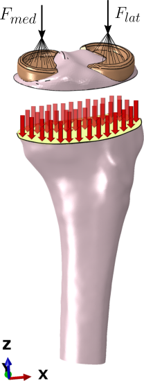
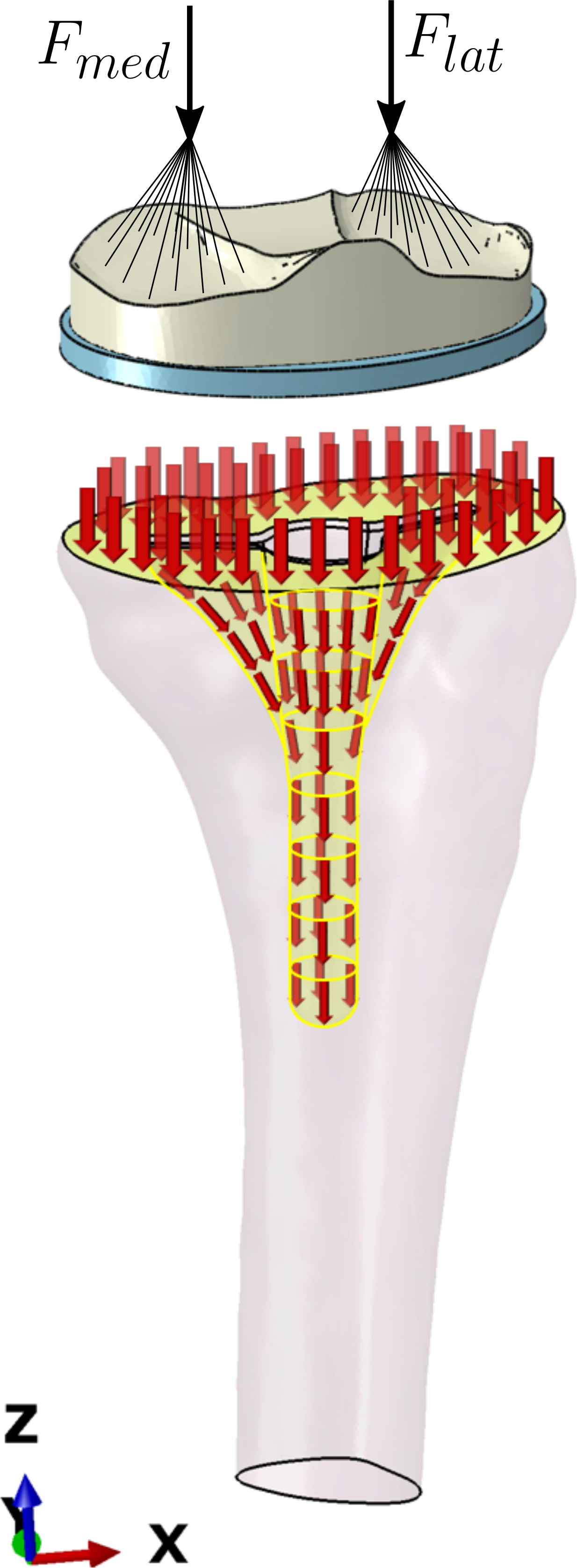
Figure 1 schematically displays the difference in the load-transfer of pre-surgery to post-surgery axial load transfer. Under pre-surgery conditions the joint forces applied by the two femoral condyles are completely transmitted by stresses in the cross-sectional plane which in surgery is chosen as the tibial resection plane. Under post-surgery conditions the axial force is decomposed according to (5), partially transmitted by the plate through normal stresses, partially by the stem through shear stresses
| (5) |
The force decomposition between plate and stem parts generally depends on stiffness of bone and implant, interface material (cemented or cement free fixation), and stem extension length. It is however clear that the force transmitted at the cross section of the base plate is in either case lowered compared to pre-surgery conditions, which implies a loss of bone loading in the proximal regions.
It is the main aim of the present work (i) to quantify the force decomposition according to (5) for the standard fixation concept, (ii) to analyze its consecutive force flow through the tibia along with a comparison to pre-surgery bone loading, and (iii) to propose a novel fixation concept that minimizes post-TKA loading reduction.
Dirichlet boundary conditions are chosen at the distal end of the modeled tibia that is all degrees of freedoms are fixed. For the Neumann conditions, only the forces acting at the tibia plate in -direction are modeled with N, Bergmann et al. [2014], Bergmann et al. [2020]. The set-up of knee joint prostheses that enable in vivo measurements of loading are described in Damm et al. [2010].
For the bone-implant interfaces we analyze various boundary conditions as detailed in Sec. 2.2.3. In either case, sticking friction conditions are set for the interface between the tibial tray and bone. For the case of a cemented fixation we assume sticking friction for the interfaces of implant-cement and cement-bone. For the cementless fixation we consider the cases of sticking friction and two different coefficients of friction.
2.2.2 Material properties
For the material behavior of tibial bone, an isotropic linear elasticity law is assumed to hold. The assumption of linear elasticity is corroborated by recent experimental findings by Juszczyk et al. [2011] and Grassi et al. [2016] (for femoral bone), the validity of isotropic elasticity in simulations is underpinned by Schileo et al. [2014]. Cowin presents orthotropic elasticity parameters for the tibia, which are however throughout constant and thus do not account for the pronounced non-homogeneity of real bone Cowin [2009]. The figures of the strongly heterogeneous Young’s modulus distribution follow from bone reconstruction as described in Sec. 2.1. The Poisson’s ratio is assumed to be constant, . For the implant material, linear elastic, isotropic material parameters are chosen for both the titanium-alloy (TiAl6V4) Long and Rack [1998] as well as for the cobalt-chrome alloy (CoCr) version. The very standard of bone cement is PMMA (Polymethyl methacrylate). Polyethylene (PE) is used for the tibial tray; moreover, we consider for its low stiffness a fictitious implant fully made of PE (all-PE). The material parameters of linear elasticity are listed in Table 1.
| Ti | CoCr | PE | PMMA | Bone | |
|---|---|---|---|---|---|
| Young’s modulus [MPa] | 110 000 | 210 000 | 1 200 | 2 200 | [30, 8 193.59] |
| Poisson’s ratio | 0.33 | 0.36 | 0.46 | 0.3 | 0.3 |
2.2.3 Variants of tibia implant system
In the numerical analysis we consider distinct cases of the tibial implant systems showing variations in geometry, material and fixation:
-
1.
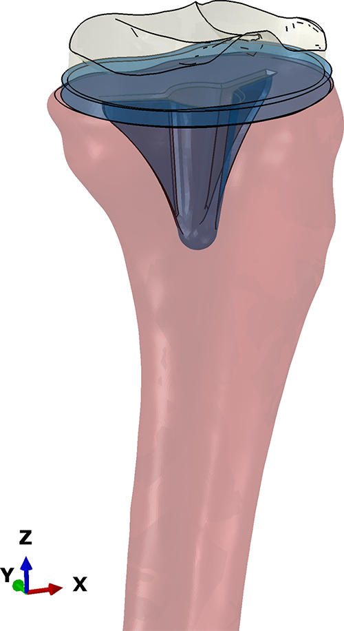
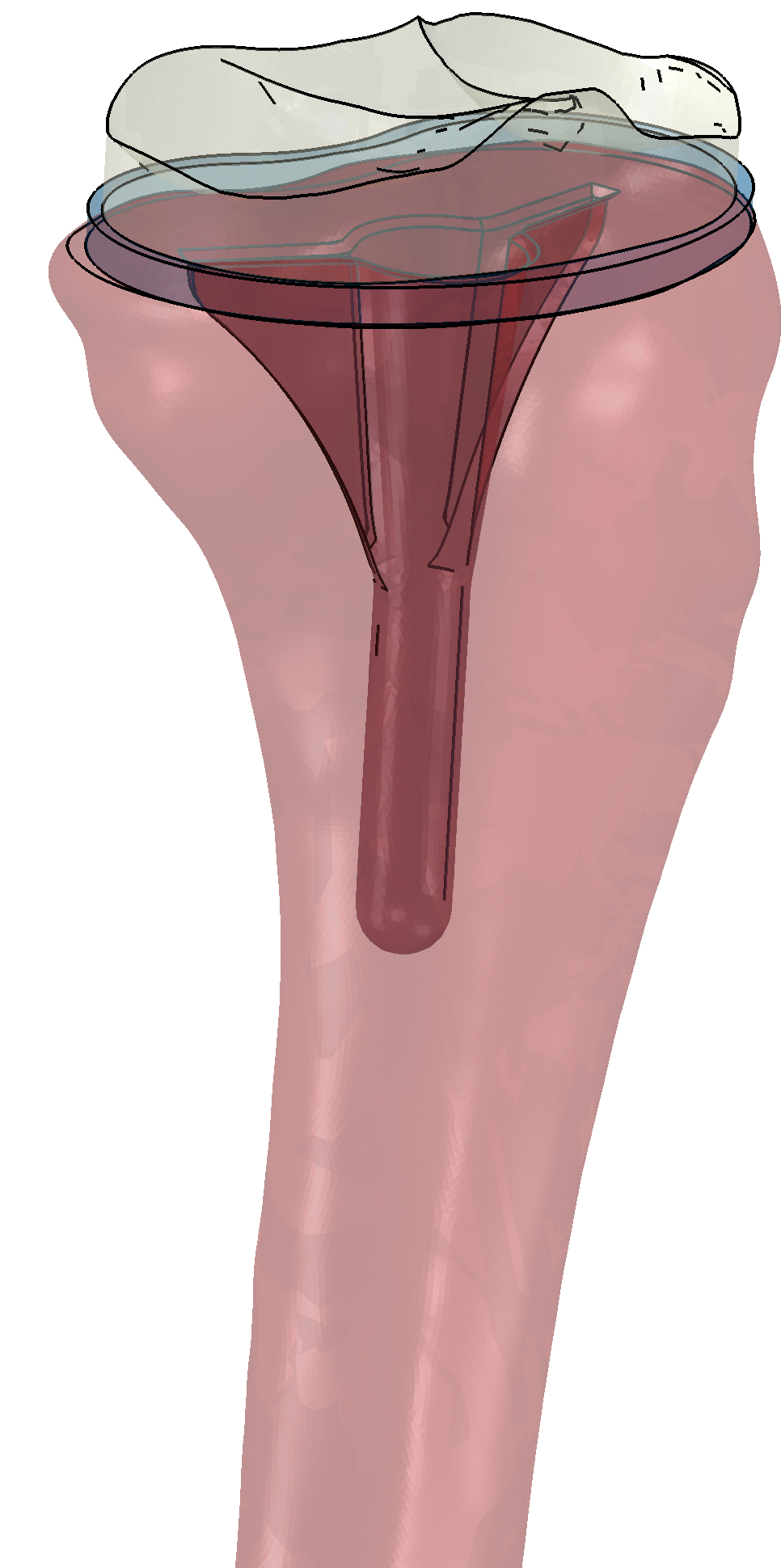
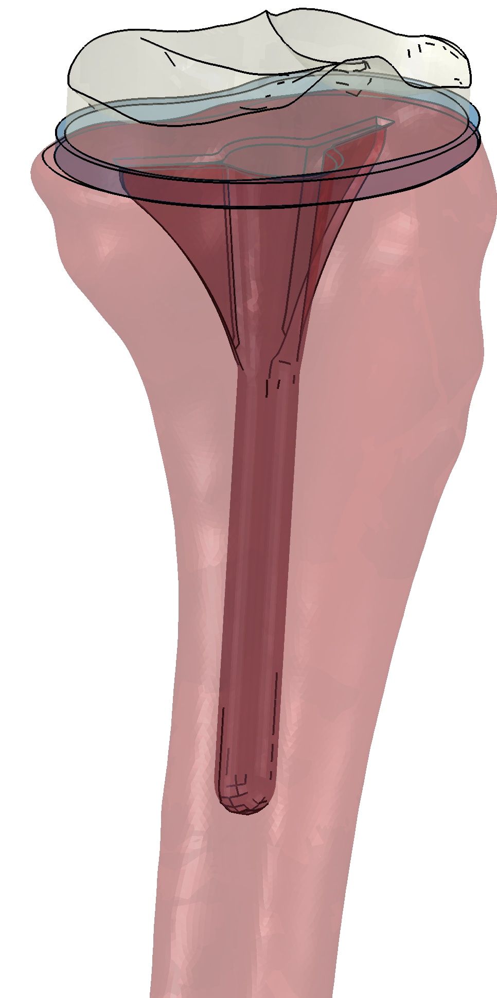
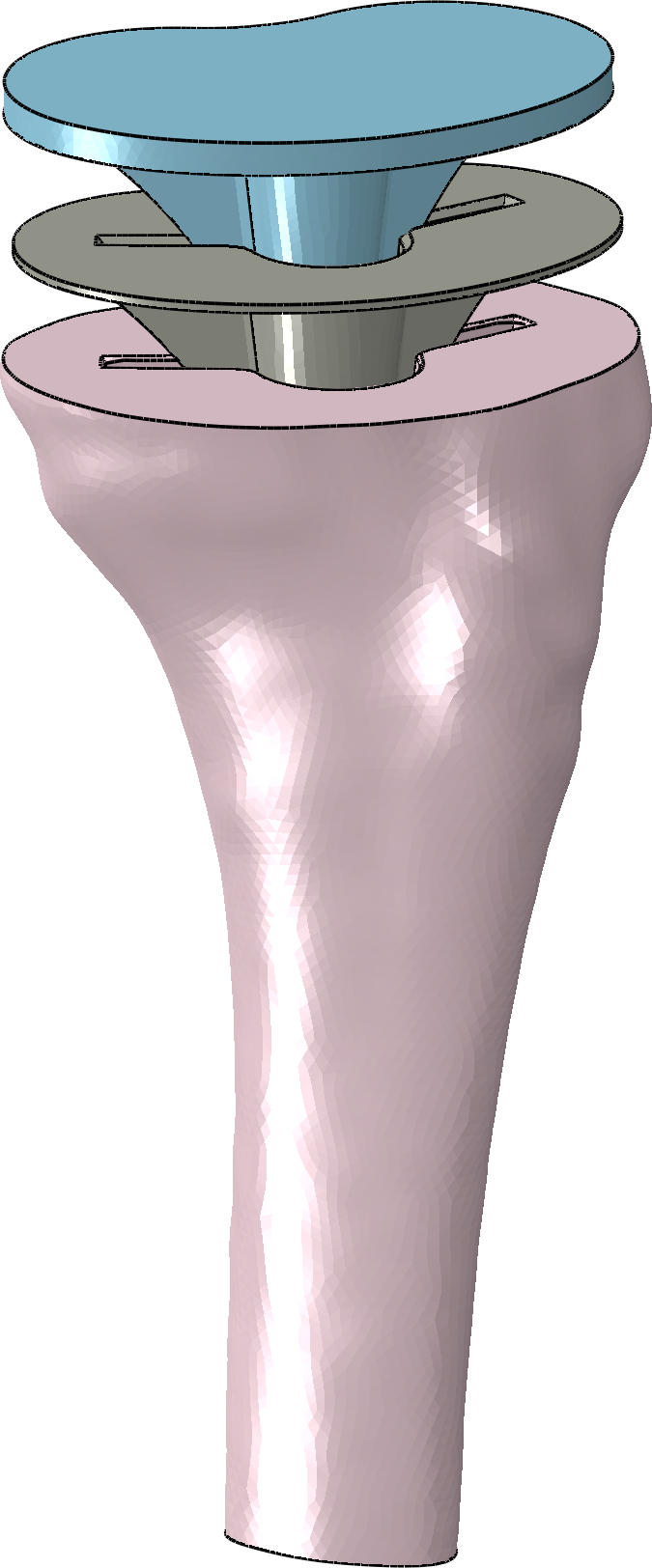
Stem extension length: {5,40,75} mm, Fig. 2 (b,c,d). Stem thickness: 10 mm.
-
2.
Material: titanium alloy (Ti), cobalt-chrome alloy (CoCr), all-polyethylene (PE). The first two are frequently referred to as metal-backed (MB).
-
3.
Implant-to-bone interface conditions: variants of sticking friction conditions and sliding friction conditions are considered. For sticking friction, the variant of (i) full cementation (FullC) and (ii) surface cementation (SurfC) along with stem fixation through press-fit and, after trabecular ingrowth, through osseointegration. For the variant of sliding friction different cases of coefficient of frictions (cof) are compared, (iii) cof=0.2 and the idealized case of (iv) cof=0.0 for perfectly smooth interfaces.
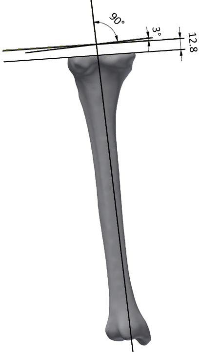
Figure 2 (a) displays the orientation of the resection plane to the mechanical axis and the thickness of maximal bone removal, the image in (e) shows the case of full cementation.
2.2.4 Measures in the numerical analysis
The strain energy density (SED), which is defined by the scalar-product of work-conjugate pairs of stress and strain tensors, here the Second Piola-Kirchhoff stress tensor and the Green-Lagrange strain tensor ,
| (6) |
is widely accepted as a mechanical stimulus for bone remodeling in biomechanics Huiskes et al. [1992], Ehrlich and Lanyon [2002], for a detailed discussion see Turner [1998], Ambrosi et al. [2011].
The relative, percental SED deviation of the post-TKA bone from the pre-TKA bone is calculated according to
| (7) |
A similar metric based on von-Mises stress instead of SED is used by Fraldi et al. [2010] –referred to as Stress Shielding Intensity SSI– and by Boyle and Kim [2011].
For a comparison among the implant variants and with the pre-surgery state, SED differences according to (7) and a decomposition of force transfer into plate and stem parts.
3 Results
3.1 Presurgery load transfer
| Spongiosa | Corticalis | |
![[Uncaptioned image]](/html/1908.09611/assets/E_Mod_2_Cut.png)
|
![[Uncaptioned image]](/html/1908.09611/assets/E_Mod_Cut.png)
|
|
| SED |
![[Uncaptioned image]](/html/1908.09611/assets/SED_Soft_Zone_cut.png)
|
![[Uncaptioned image]](/html/1908.09611/assets/SED_Stiff_Zone_cut.png)
|
The images in Tab. 2 display the heterogeneous Young’s modulus distribution and the consecutive SED distribution in the tibia. Two different ranges are each chosen for visualization to account for the considerable differences between spongious and cortical bone in stiffness. As a consequence, SED distributions similarly exhibit a corresponding variation, which underpins that stiffness ”attracts” bone loading in terms of SED.
Notice that in the most proximal cross section (which approximately coincides with the surgical resection plane) tibial bone is mostly spongious attaining stiffness above 1500 MPa only at some spots. The considerably stiffer corticalis continuously forms a closed ring of increasing thickness in more distal cross sections.
The distributions of Young’s modulus and pre-surgery SED are the key reference for a proper interpretation of the post-surgery SED changes.
3.2 Postsurgery load transfer at the implant-bone interfaces
| force transmission ratio [%] plate : stem | |||||
|---|---|---|---|---|---|
| interface conditions | implant | extension length [mm] | |||
| contact | cementation | material | 75 | 40 | 5 |
| sticking friction | FullC | CoCr | : | : | : |
| Ti | : | : | : | ||
| PE | : | : | : | ||
| SurfC | CoCr | : | : | : | |
| Ti | : | : | : | ||
| PE | : | : | : | ||
| sliding friction cof=0.2 | SurfC | CoCr | : | : | : |
| Ti | : | : | : | ||
| PE | : | : | : | ||
| cof=0.0 | SurfC | CoCr | : | : | : |
| Ti | : | : | : | ||
| PE | : | : | : | ||
Table 3 decomposes the force in -direction of the coordinate system of Fig. 2 into its plate and stem parts.
-
1.
The larger the stiffness of the implant material along with the stiffness of the stem-bone interface, the smaller the plate:stem force ratio; for the stiffest case (CoCr for FullC) the ratio of 17:83 indicates a stem-dominated force transmission, for the most compliant case (PE for SurfC/sliding friction at cof=0.0) the ratio of 84:16 indicates a plate-dominated force transfer.
-
2.
Point (1) with its upper and lower bounds for force ratios spans a wide interval where a further analysis reveals the impacts of interface conditions and stem lengths.
-
(a)
For sliding friction/SurfC the plate transmits a considerably larger force portion than for sticking friction conditions. This is true for the metal-backed (MB) variants along with 75mm and 40mm stem extension lengths. For the 5 mm case however, the difference between sticking and sliding friction mostly vanishes.
-
(b)
For sticking friction conditions, in both the FullC and SurfC cases, it holds that the longer the stem, the larger the force portion transmitted by the stem. For sliding friction conditions, in both the cof=0.2 and cof=0.0 cases, the same is true, but only for stem extension lengths of 40 mm and 75 mm. In the 5mm case however in sliding friction, the force transmitted by the stem is throughout larger than for the longer stems.
-
(c)
The plate:stem force ratio is invariant with respect to interface conditions (sticking or gliding) only for the short stem.
-
(a)
-
3.
The PE case is an exception to the above rules in that it is almost invariant with respect to stem length and interface conditions; the force portion transmitted through the plate is constant at around 80%.
Elementary mechanical reasoning suggests that the larger the force part mediated by the plate, the larger the tibial bone loading into proximal bone and more distal regions. Notice in this context that in natural, pre-surgery conditions the applied force is completely transmitted through that tibial plane which is chosen in surgery to be resection plane. In Sec. 3.3 we show that the plate-to-stem force decomposition is in fact a reliable indicator for post-surgery to pre-surgery SED changes according to (7) in the proximal tibia.
In reality, the cement usually balloons out at the tip region of the stem, frequently contacting the posterior cortex and undoubtedly transmitting loads in the area. In that case the axial force portion transmitted by the stem is expected to rise. In the present analysis however, where a 40 mm stem along with a balloon of 10 mm diameter is considered, force transmission remains unaltered Tab. 4, which indicates that a stiff bridge to the cortex was not established. For the uncemented stem the tip conditions –hollow versus spongy bone– similarly have minor influence on force transmission.
| force transmission ratio [%] plate : stem | |||||
|---|---|---|---|---|---|
| interface conditions | implant | stem tip conditions | |||
| contact | cementation | material | hollow | spongy bone | cement balloon |
| sliding friction cof=0.2 | SurfC | Ti | : | : | – |
| sticking friction | FullC | Ti | – | : | : |
3.3 Postsurgery SED differences
| stem | Full cementation | —————— Surface cementation —————— | ||
|---|---|---|---|---|
| length | —— sticking friction conditions —— | —— sliding friction conditions —— | ||
| (mm) | thickness 2mm | osseointegration | cof=0.2 | cof=0.0 |
| 75 |
![[Uncaptioned image]](/html/1908.09611/assets/SED_Diff_Redn_Zone_75mm_Ti_Imp_Ce_2mm_All_Tie_cut.png)
|
![[Uncaptioned image]](/html/1908.09611/assets/SED_Diff_Redn_Zone_75mm_Ti_Imp_All_Tie.png)
|
![[Uncaptioned image]](/html/1908.09611/assets/SED_Diff_Reduction_Zone_75mm_Ti_COF02.png)
|
![[Uncaptioned image]](/html/1908.09611/assets/SED_Diff_Redn_Zone_75mm_Ti_Imp_NContact.png)
|
| 23:77 | 29:71 | 59:41 | 72:28 | |
| 40 |
![[Uncaptioned image]](/html/1908.09611/assets/SED_Diff_Redn_Zone_40mm_Ti_Imp_Ce_2mm_All_Tie_cut.png)
|
![[Uncaptioned image]](/html/1908.09611/assets/SED_Diff_Reduction_Zone_40mm_Ti_Imp_All_Tie_cut.png)
|
![[Uncaptioned image]](/html/1908.09611/assets/SED_Diff_Reduction_Zone_40mm_Ti_COF02_cut.png)
|
![[Uncaptioned image]](/html/1908.09611/assets/SED_Diff_Reduction_Zone_40mm_Ti_Imp_NContact_cut.png)
|
| 30:70 | 44:56 | 72:28 | 77:23 | |
| 5 |
![[Uncaptioned image]](/html/1908.09611/assets/SED_Diff_Redn_Zone_5mm_Ti_Imp_Ce_2mm_All_Tie_cut.png)
|
![[Uncaptioned image]](/html/1908.09611/assets/SED_Diff_Redn_Zone_5mm_Ti_Imp_All_Tie_cut.png)
|
![[Uncaptioned image]](/html/1908.09611/assets/SED_Diff_Reduction_Zone_5mm_Ti_COF02_cut.png)
|
![[Uncaptioned image]](/html/1908.09611/assets/SED_Diff_Redn_Zone_5mm_Ti_Imp_NContact_cut.png)
|
| 55:45 | 62:38 | 56:44 | 62:38 | |
The impact of interface conditions and stem extension length on SED differences is visualized in Table 5 for the Ti-alloy implant.
-
•
The lower the shear stiffness of the stem-bone interface, (decreasing from left to right in Table. 5) the smaller the post-surgery SED loss both in intensity and spatial extension.
-
•
The longer the stem extension in the case of sticking friction, the stronger and more distally extended is the SED loss, a consequence which is even more pronounced for the fully cemented fixation than for the case of press-fit/osseointegration at the stem. For sliding friction conditions however, the influence of stem length on post-surgery SED loss is confined to the proximal tibia, but distally very limited.
-
•
The newly introduced force decomposition into plate and stem parts is a definite, reliable measure for the intensity and spatial extension of post-surgery SED reduction; if primarily the plate transmits the axial force, SED reduction is confined in magnitude and to small regions in most proximal cross sections, for the case of stem-mediated force transmission the opposite is true.
| interface | CoCr alloy | Ti-alloy | all-PE |
|---|---|---|---|
| conditions | =220 000 MPa | =110 000 MPa | =1200 MPa |
| sticking friction |
![[Uncaptioned image]](/html/1908.09611/assets/SED_Diff_Redn_Zone_40mm_CoCr_Imp_All_Tie.png)
|
![[Uncaptioned image]](/html/1908.09611/assets/SED_Diff_Reduction_Zone_40mm_Ti_Imp_All_Tie.png)
|
![[Uncaptioned image]](/html/1908.09611/assets/SED_Diff_Redn_Zone_40mm_PE_Imp_All_Tie.png)
|
| 42:58 | 44:56 | 81:19 | |
| sliding friction cof=0.2 |
![[Uncaptioned image]](/html/1908.09611/assets/SED_Diff_Redn_Zone_40mm_CoCr_Imp_NContact.png)
|
![[Uncaptioned image]](/html/1908.09611/assets/SED_Diff_Reduction_Zone_40mm_Ti_Imp_NContact.png)
|
![[Uncaptioned image]](/html/1908.09611/assets/SED_Diff_Redn_Zone_40mm_PE_Imp_NContact.png)
|
| 77:23 | 77:23 | 84:16 |
The impact of the implant material on SED-changes is shown in Table 6. The comparison of the CoCr-case with the Ti-alloy case indicates that stiffness change of the implant material, here roughly 2:1, has very little influence on SED changes compared to pre-surgery conditions, which is true for both sticking and sliding friction conditions at low friction coefficients. It is only the sticking friction case, where the drastic Young’s modulus reduction from CoCr/Ti (210/110 GPa) to PE (1.2 GPa) material (Young’s modulus ratio Ti-alloy to PE: 91) does considerably avoid SED loss. For sliding friction however, the improvement of the fully PE implant compared to the much stiffer materials CoCr and Ti is minor.
If the stiffnesses of bone and implant are decoupled by sliding friction conditions, the stiffness of the implant does not matter; the all-PE variant exhibits almost the same SED-differences as the much stiffer Ti-alloy does. Only in the case of sticking friction realized by full cementation or osseointegration, material stiffness has a stronger impact on stress shielding.
4 Discussion
4.1 What is and what drives stress shielding? How can it be overcome?
Stress shielding refers to the reduction in bone density caused by a reduction of physiological stress from the bone by a stiff, metallic implant. This is because of bone’s adaptivity to remodel in response to the loads referred to as Wolff’s law. As a consequence, a decrease of loading on bone decreases bone density and stiffness because of the lowered stimulus for maintaining the existing bone density.
While none of these statements is wrong, the present work suggests a distinguished analysis of stress shielding with respect to its roots.
The point of departure is the finding that the force transmitted by the tibial plate is relatively small, if the stem is rigidly connected to bone, either by press-fit/osseointegration in cementless fixation (referred to as surface cementation) or by cemented fixation (referred to as full cementation). In that case, it is the stem which transmits by shear stresses the majority of the applied load in axial direction into bone. As a consequence, the proximal regions in the tibia suffer from considerable SED reduction; in view of the necessity for vital bone cells to get fed by loading it can be seen as a SED-starvation. This effect expands to more distal tibia parts the longer the tibial stem extension.
The present work shows that the key aspect to overcome stress shielding in tibial bone is the mechanical activation of the tibia plate for the implant-to-bone force transfer. The activation is realized by resolving the sticking connection between implant stem and bone111The plate remains fixed to bone by cement (PMMA)., which implies that the cemented interface shall be avoided. For the case of sliding friction in the regime of low coefficients of friction (cof=0.2) SED reduction is bounded to modest magnitude almost everywhere, if present at all.
The above described effects follow the regime of decreasing stiffnesses: FullC SurfC/osseointegration SurfC/sliding friction, cof=0.2 sliding friction, cof=0.0. The comparison of FullC with SurfC for sticking friction (hence the two stiffest cases in the above hierarchy) was analyzed in Cawley et al. [2013], where the authors find a stress reduction under the tibial baseplate for both cases, but stronger for the full cementation.
Impact of implant-to-bone stiffness mismatch. Even if the considerable stiffness mismatch between implant material and bone persists (140:1 for the CrMo case, 73:1 for the Ti-alloy) stress shielding is overcome for compliant stem-to-bone interface conditions.
Remarkably, in terms of SED-preservation the fully polyethylene implant (=1200 MPa) rigidly connected to bone does not excel the Ti-based implant, if the latter exhibits a smooth stem surface avoiding force transmission by shear.
The notion of stress-shielding as an inevitable consequence of the implant-bone stiffness mismatch is misleading, since stress shielding becomes effective only for a rigid stem-to-bone connection, by cementation or osseointegration. Among great many descriptions of the mechanical sources of stress-shielding, Gefen’s definition is one of the very few precise ones Gefen [2002].
The smaller the stiffness of the stem-to-bone connection, the lower the SED-reduction. This is a simple consequence of a reduced force transfer through the plate for stiffer shear support along the stem. The simulation results underpin this hierarchy. The use of short-keeled cemented tibial components however is no generally best solution, since an increased risk for aseptic loosening was reported Ries et al. [2013].
4.2 Post-TKA excess SED, source and consequences
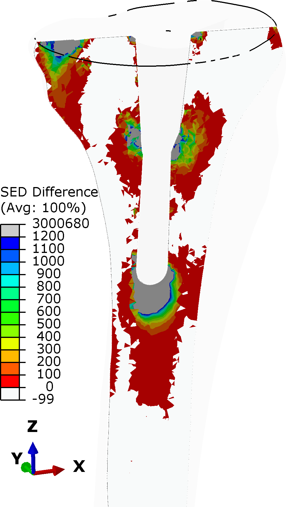
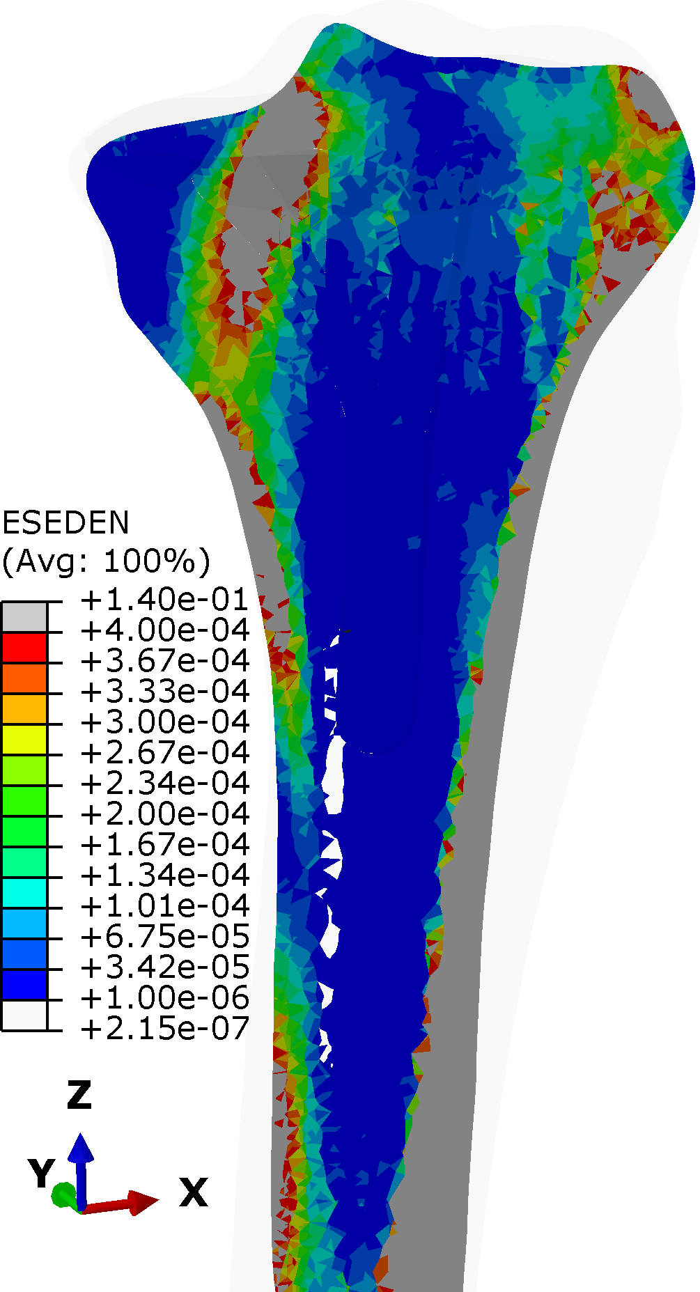
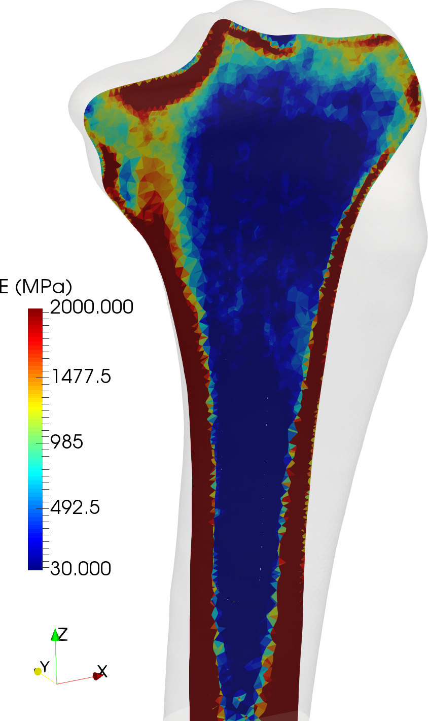
In all cases considered in Tables 5 and 6 some regions indicate a drastic post-surgery SED increase, which calls for a mechanical explanation addressing whether it is of harm. To put things into perspective, the images in Figure 3 (a) and (b) underpin that despite the huge maximal values of SED increase, excess SED is bounded both in magnitude and spatial extension. Moreover, it becomes transparent that along the stem the SED increase is in the soft spongious core of the tibia, where pre-surgery tibia exhibits low SED values (c) due to low stiffness (d) such that a drastic post-surgery increase does not necessarily exceed the bone strength.

4.3 Realization
The novel fixation concept can be realized without considerable changes in implant geometry and surgery techniques. The surface of the stem must be sufficiently smooth. For realizing a low-friction regime at the implant-bone interface, a protective thin film of a biocompatible Diamond-Like Carbon (DLC) is favorable and well-established for its excellent bio- and hemocompatibility Robertson [2002]. Friction coefficients generally in the range of 0.05-0.2 have been reported for DLC Grill [1997] which are considerably lower than oxidized Ti-alloy surfaces Ramos-Saenz et al. [2010].
In classification point of view, the proposed concept belongs to the case of surface cementation along with a press-fitting of the tibial stem in the tibial physis at vanishing press fit and very small friction coefficient. This implies decreased bone loss on revision compared to a stem rigidly connected to bone either by cementation or osseointegration.
4.4 Stability in view of micromotion
Since the stem is no longer rigidly connected to bone, neither by cementation nor by osseointegration, there is relative motion in axial direction of the stem with respect to bone. Since the stem still interacts with surrounding bone through normal contact, it contributes to stiffness and stability of the implant most notably for loading conditions with transverse forces and bending at the knee joint.
Primary stability refers to the relative position stability on short terms after surgery, for cementless implantation by means of a press-fit which is continuously replaced in the healing process by secondary stability through osseointegration. To enable osseointegration the restriction of micromotion to small values is crucial. This context elucidates why in the present concept, where the stem is not rigidly connected to bone, primary stability in terms of confined micromotion need not be strictly enforced.
For standard implantation, micromotion is frequently an indicator or even a major cause of aseptic loosening of the tibial component thus leading to TKA failure Vanlommel et al. [2011]. But this is true for full cementation, where micromotion is not intended and induces at rough implant-cement-bone interfaces harmful wear particles Jacobs et al. [1994]. This is in stark contrast to the present concept of a smooth stem enabling debris-free micromotion based on judiciously selected surface material as described in Sec. 4.3. In this context it should be noted that the lower part of short stem hip endoprosthesis are typically smooth; they have the function to stabilize the position of the implant though they have no fixation to bone by osseointegration. Notice that suchlike design is observed for a multitude of implant models where the high primary stability is further enhanced by the rounded tip of the stem guided along the dorso-lateral cortex.
4.5 Transferability and limitations
Since the plate-based force transfer mimics on purpose the pre-surgery physiological conditions, it is justified to assume that the favorable characteristics are preserved no matter how patient-specific bone data or loading conditions may differ from the particular settings of the present work. Reliable conclusions clearly require further simulation results.
Remodeling depends on mechanical stimulus, biochemical processes, on age, sex and individual disposition showing considerable scatter between individuals. As a consequence, models for remodeling necessarily contain uncertainties and simulations cannot be predictive in a deterministic way.
The proposed fixation concept crucially relies on sufficient stiffness and strength of tibial bone in the resection plane, which is, however, not stronger loaded than in presurgery, physiological conditions. In conclusion, the key premise to apply the proposed concept of avoiding stress-shielding along with bone resorption, is that other medical indications do not overrule this aspect.
There are several simplifications in the model in terms of one single loading instead of a full gait analysis Galloway et al. [2013], Bergmann et al. [2014], thereby restricting to pure axial forces and e.g. no shear forces, no consideration of muscles and ligaments. Moreover, the cement mantle is assumed to exhibit constant thickness, clearly an idealization Taylor and Prendergast [2015]. The same is true for the assumption of sticking friction condition everywhere on the stem surface.
All findings are predictions from the lab in silico, since experimental results of the lab in vitro or even from clinical research in vivo are missing.
4.6 Implant fixation at knee compared to hip – a broader perspective
The present work adopts the idea of Eidel et al. [2018] for a novel fixation concept of short-stem hip implants. Therein, the concept is referred to as ”collar-cortex compression concept (CO4)” for describing the key mechanisms of force transmission for avoiding SED-reduction. The crucial aspect of modified interface conditions is transferable beyond the existing considerable differences between fixation of the plate-stem system into femur and tibia in view of different geometries, loading conditions, stiffness distributions to name but a few differences. For the hip implant however, the current generation of models typically do not exhibit a plate device while it is standard in TKA. Remarkably, the idea of the mechanical activation of cortical bone in the resection plane by a pre-stressed thrust-plate for a hip implant was introduced already by Huggler and Jacob [1995].
5 Conclusions
The main results and conclusions of the present work can be summarized as follows:
-
•
The stiffer the stem-bone interface, (i) the larger (smaller) the force fraction transmitted through the stem (plate), and (ii) the more pronounced the post-surgery SED reduction, hence stress-shielding.
-
•
Vice versa, force transmission primarily mediated through the tibial plate mechanically activates proximal tibia and confines SED reduction to an unprecedented extent both in intensity and spatially distal extension.
-
•
Stress shielding can be avoided even for a metallic implant despite its large implant-to-bone stiffness mismatch, if the stem-bone interface is sufficiently compliant in terms of sliding friction conditions.
-
•
The newly introduced force decomposition ratio of plate-stem is a reliable indicator of post-surgery SED changes.
-
•
The base-plate force transmission concept follows a bionics perspective in that it mimics pre-surgery conditions of axial force transmission.
-
•
For surgery practice in TKA the established standard set-up can be preserved; the implant geometry and materials, the cemented base-plate to bone interface and therefore all techniques and procedures. For revision surgery the novel concept of tibial implant fixation is favorable for its missing rigid connection of stem to bone.
-
•
In spite the considerable differences in geometry, stiffness and loading conditions, the main characteristics of a recently proposed concept for the fixation of short stem hip endoprostheses in Eidel et al. [2018] are transferable to the tibial implant fixation.
Declarations of interest: None.
Funding: This research did not receive any specific grant from funding agencies in the public, commercial, or not-for-profit sectors.
Acknowledgments: BE acknowledges support by the Deutsche Forschungsgemeinschaft (DFG) within the Heisenberg program (grant no. EI 453/5-1).
References
- Ambrosi et al. [2011] D. Ambrosi, G. A. Ateshian, E. M. Arruda, S. C. Cowin, J. Dumais, A. Goriely, G. A. Holzapfel, J. D. Humphrey, R. Kemkemer, E. Kuhl, J. E. Olberding, L. A. Taber, and K. Garikipati. Perspectives on biological growth and remodeling. J. Mech Phys. Solids, 59(4):863–883, 2011. ISSN 0022-5096. doi: 10.1016/j.jmps.2010.12.011.
- Au et al. [2007] Anthony G. Au, V. James Raso, A. B. Liggins, and A. Amirfazli. Contribution of loading conditions and material properties to stress shielding near the tibial component of total knee replacements. J. Biomech., 40(6):1410–1416, 2007. doi: 10.1016/j.jbiomech.2006.05.020.
- Bergmann et al. [2020] G. Bergmann, A. Bender, Graichen, F., Dymke, J., A. Rohlmann, A. Trepczynski, M. O. Heller, and I. Kutzner. Orthoload - loading of orthopaedic implants: Additional data: walking-all-load-levels. 2020. URL https://orthoload.com/wp-content/uploads/Walking_AllLoadLevels.png.
- Bergmann et al. [2014] Georg Bergmann, Alwina Bender, Friedmar Graichen, Jörn Dymke, Antonius Rohlmann, Adam Trepczynski, Markus O. Heller, and Ines Kutzner. Standardized loads acting in knee implants. PloS one, 9(1):e86035, 2014. doi: 10.1371/journal.pone.0086035.
- Boyle and Kim [2011] Christopher Boyle and Il Yong Kim. Comparison of different hip prosthesis shapes considering micro-level bone remodeling and stress-shielding criteria using three-dimensional design space topology optimization. J. Biomech., 44(9):1722–1728, 2011. doi: 10.1016/j.jbiomech.2011.03.038.
- Carr et al. [2012] Andrew J. Carr, Otto Robertsson, Stephen Graves, Andrew J. Price, Nigel K. Arden, Andrew Judge, and David J. Beard. Knee replacement. Lancet, 379(9823):1331–1340, 2012. ISSN 01406736. doi: 10.1016/S0140-6736(11)60752-6.
- Cawley et al. [2012] Derek T. Cawley, Nicola Kelly, Andrew Simpkin, Fintan J. Shannon, and J. Patrick McGarry. Full and surface tibial cementation in total knee arthroplasty: a biomechanical investigation of stress distribution and remodeling in the tibia. Clin. Biomech., 27(4):390–397, 2012. doi: 10.1016/j.clinbiomech.2011.10.011.
- Cawley et al. [2013] Derek T. Cawley, Nicola Kelly, J. Patrick McGarry, and Fintan J. Shannon. Cementing techniques for the tibial component in primary total knee replacement. The Bone and Joint Journal, 95-b(3):295–300, 2013. doi: 10.1302/0301-620X.95B3.
- Completo et al. [2009] A. Completo, P. Talaia, F. Fonseca, and J. A. Simões. Relationship of design features of stemmed tibial knee prosthesis with stress shielding and end-of-stem pain. Mater. Design, 30(4):1391–1397, 2009. ISSN 02613069. doi: 10.1016/j.matdes.2008.06.071.
- Cowin [2009] Stephen C. Cowin. Bone mechanics handbook. CRC Press, New York, 2nd ed. edition, 2009. ISBN 978-0849391170.
- Damm et al. [2010] Philipp Damm, Friedmar Graichen, Antonius Rohlmann, Alwina Bender, and Georg Bergmann. Total hip joint prosthesis for in vivo measurement of forces and moments. Med. Eng. Phys., 32(1):95–100, 2010. doi: 10.1016/j.medengphy.2009.10.003.
- Ehrlich and Lanyon [2002] P. J. Ehrlich and Lance E. Lanyon. Mechanical strain and bone cell function: a review. Osteoporosis Int., 13(9):688–700, 2002. ISSN 0937-941X. doi: 10.1007/s001980200095.
- Eidel et al. [2018] B. Eidel, A. Gote, A. Ohrndorf, and H-J Christ. How can a short stem hip implant preserve the natural, pre-surgery force flow? a finite element analysis on a collar cortex compression concept (co4). Med. Eng. Phys., 58:1–12, 2018. doi: 10.1016/j.medengphy.2018.04.016.
- Fraldi et al. [2010] M. Fraldi, L. Esposito, G. Perrella, A. Cutolo, and S. C. Cowin. Topological optimization in hip prosthesis design. Biomech. Model. Mechan., 9(4):389–402, 2010. doi: 10.1007/s10237-009-0183-0.
- Gallo et al. [2013] J. Gallo, S. B. Goodman, Y. T. Konttinen, M. A. Wimmer, and M. Holinka. Osteolysis around total knee arthroplasty: a review of pathogenetic mechanisms. Acta Biomater., 9(9):8046–8058, 2013. doi: 10.1016/j.actbio.2013.05.005.
- Galloway et al. [2013] Francis Galloway, Max Kahnt, Heiko Ramm, Peter Worsley, Stefan Zachow, Prasanth Nair, and Mark Taylor. A large scale finite element study of a cementless osseointegrated tibial tray. J. Biomech., 46(11):1900–1906, 2013. doi: 10.1016/j.jbiomech.2013.04.021.
- Gefen [2002] A. Gefen. Computational simulations of stress shielding and bone resorption around existing and computer-designed orthopaedic screws. Med. Biol. Eng. Comput., 40(3):311–322, 2002. ISSN 0140-0118. doi: 10.1007/BF02344213.
- Grassi et al. [2016] Lorenzo Grassi, Sami P. Väänänen, Matti Ristinmaa, Jukka S. Jurvelin, and Hanna Isaksson. How accurately can subject-specific finite element models predict strains and strength of human femora? investigation using full-field measurements. J. Biomech., 49(5):802–806, 2016. doi: 10.1016/j.jbiomech.2016.02.032.
- Grill [1997] A. Grill. Tribology of diamondlike carbon and related materials: an updated review. Surface and Coatings Technology, 94-95:507–513, 1997. ISSN 02578972. doi: 10.1016/S0257-8972(97)00458-1.
- Huggler and Jacob [1995] A. H. Huggler and H. A. C. Jacob. The development of the thrust plate prosthesis. In E. W. Morscher, editor, Endoprosthetics, pages 248–257. Springer Berlin Heidelberg, Berlin, Heidelberg, 1995. ISBN 978-3-642-79308-0. doi: 10.1007/978-3-642-79306-6–“textunderscore˝18.
- Huiskes et al. [1992] R. Huiskes, H. Weinans, and B. van Rietbergen. The relationship between stress shielding and bone resorption around total hip stems and the effects of flexible materials. Clin. Orthop. Relat. R., (274):124–134, 1992. ISSN 0009-921X.
- Innocenti et al. [2009] Bernardo Innocenti, Evelyn Truyens, Luc Labey, Pius Wong, Jan Victor, and Johan Bellemans. Can medio-lateral baseplate position and load sharing induce asymptomatic local bone resorption of the proximal tibia? a finite element study. J. Orthop. Surg. Res., 4(1):26, 2009. ISSN 1749-799X. doi: 10.1186/1749-799X-4-26.
- Jacobs et al. [1994] J. J. Jacobs, A. Shanbhag, T. T. Glant, J. Black, and J. O. Galante. Wear debris in total joint replacements. The Journal of the American Academy of Orthopaedic Surgeons, 2(4):212–220, 1994. doi: 10.5435/00124635-199407000-00004.
- Juszczyk et al. [2011] Mateusz Maria Juszczyk, Luca Cristofolini, and Marco Viceconti. The human proximal femur behaves linearly elastic up to failure under physiological loading conditions. J. Biomech., 44(12):2259–2266, 2011. doi: 10.1016/j.jbiomech.2011.05.038.
- Long and Rack [1998] M. Long and H. J. Rack. Titanium alloys in total joint replacement–a materials science perspective. Biomaterials, 19(18):1621–1639, 1998. ISSN 0142-9612.
- Martin et al. [2017] J. Ryan Martin, Chad D. Watts, Daniel L. Levy, and Raymond H. Kim. Medial tibial stress shielding: A limitation of cobalt chromium tibial baseplates. J. Arthroplasty, 32(2):558–562, 2017. doi: 10.1016/j.arth.2016.07.027.
- Ramos-Saenz et al. [2010] C. R. Ramos-Saenz, P. A. Sundaram, and N. Diffoot-Carlo. Tribological properties of ti-based alloys in a simulated bone-implant interface with ringer’s solution at fretting contacts. J. Mech. Behav. Biomed., 3(8):549–558, 2010. doi: 10.1016/j.jmbbm.2010.06.006.
- Rho et al. [1995] J. Y. Rho, M. C. Hobatho, and R. B. Ashman. Relations of mechanical properties to density and ct numbers in human bone. Med. Eng. Phys., 17(5):347–355, 1995. doi: 10.1016/1350-4533(95)97314-F.
- Ries et al. [2013] Christian Ries, Markus Heinichen, Florian Dietrich, Eike Jakubowitz, Christian Sobau, and Christian Heisel. Short-keeled cemented tibial components show an increased risk for aseptic loosening. Clin. Orthop. Relat. R., 471(3):1008–1013, 2013. ISSN 0009-921X. doi: 10.1007/s11999-012-2630-y.
- Robertson [2002] J. Robertson. Diamond-like amorphous carbon. Mat. Sci. Eng. R., 37(4-6):129–281, 2002. ISSN 0927796X. doi: 10.1016/S0927-796X(02)00005-0.
- Schileo et al. [2014] Enrico Schileo, Luca Balistreri, Lorenzo Grassi, Luca Cristofolini, and Fulvia Taddei. To what extent can linear finite element models of human femora predict failure under stance and fall loading configurations? J. Biomech., 47(14):3531–3538, 2014. doi: 10.1016/j.jbiomech.2014.08.024.
- Schlegel et al. [2015] Ulf J. Schlegel, Nicholas E. Bishop, Klaus Püschel, Michael M. Morlock, and Katrin Nagel. Comparison of different cement application techniques for tibial component fixation in tka. Int. Orthop., 39(1):47–54, 2015. doi: 10.1007/s00264-014-2468-x.
- Scott and Biant [2012] C. E. H. Scott and L. C. Biant. The role of the design of tibial components and stems in knee replacement. J. Bone Joint Surg. Br., 94(8):1009–1015, 2012. doi: 10.1302/0301-620X.94B8.28289.
- Sharkey et al. [2014] Peter F. Sharkey, Paul M. Lichstein, Chao Shen, Anthony T. Tokarski, and Javad Parvizi. Why are total knee arthroplasties failing today—has anything changed after 10 years? J. Arthroplasty, 29(9):1774–1778, 2014. ISSN 1532-8406. doi: 10.1016/j.arth.2013.07.024.
- Skou et al. [2015] Søren T. Skou, Ewa M. Roos, Mogens B. Laursen, Michael S. Rathleff, Lars Arendt-Nielsen, Ole Simonsen, and Sten Rasmussen. A randomized, controlled trial of total knee replacement. The New England journal of medicine, 373(17):1597–1606, 2015. doi: 10.1056/NEJMoa1505467.
- Taddei et al. [2007] Fulvia Taddei, Enrico Schileo, Benedikt Helgason, Luca Cristofolini, and Marco Viceconti. The material mapping strategy influences the accuracy of ct-based finite element models of bones: an evaluation against experimental measurements. Med. Eng. Phys., 29(9):973–979, 2007. doi: 10.1016/j.medengphy.2006.10.014.
- Taylor and Prendergast [2015] Mark Taylor and Patrick J. Prendergast. Four decades of finite element analysis of orthopaedic devices: where are we now and what are the opportunities? J. Biomech., 48(5):767–778, 2015. doi: 10.1016/j.jbiomech.2014.12.019.
- Turner [1998] C. H. Turner. Three rules for bone adaptation to mechanical stimuli. Bone, 23(5):399–407, 1998. ISSN 8756-3282.
- United States National Library of Medicine () [NLM] United States National Library of Medicine (NLM). The visibile human project. URL https://en.wikipedia.org/wiki/Visible_Human_Project.
- [40] University of Iowa Cerver College of Medicine Magnetic Resonance Research. The visible human project ct datasets. URL https://mri.radiology.uiowa.edu/visible_human_datasets.html.
- Vanlommel et al. [2011] Jan Vanlommel, Jean Philippe Luyckx, Luc Labey, Bernardo Innocenti, Ronny de Corte, and Johan Bellemans. Cementing the tibial component in total knee arthroplasty: which technique is the best? J. Arthroplasty, 26(3):492–496, 2011. doi: 10.1016/j.arth.2010.01.107.
- Viceconti et al. [1996] M. Viceconti, M. Casali, B. Massari, L. Cristofolini, S. Bassini, and A. Toni. The ’standardized femur program’ proposal for a reference geometry to be used for the creation of finite element models of the femur. J. Biomech., 29(9):1241, 1996. ISSN 0021-9290.
- Zhang et al. [2016] Qing-Hang Zhang, Andrew Cossey, and Jie Tong. Stress shielding in periprosthetic bone following a total knee replacement: Effects of implant material, design and alignment. Med. Eng. Phys., 38(12):1481–1488, 2016. doi: 10.1016/j.medengphy.2016.09.018.