MHD supernova explosions – Large-scale magnetic field effects
Abstract
We examine the effect of uniform ambient magnetic fields on the evolution of supernova-driven blast waves into a homogeneous ambient ISM in thermal equilibrium. Using the Pencil Code we simulate high resolution nonideal magnetohydrodynamic simulations in 3D. We find that supernova blast waves are sensitive to plane-parallel magnetic fields of strength in excess of 1 G for ambient gas number density 1 cm-3. Perpendicular to the field, the inward magnetic pressure gradient induces retrograde mass accretion in the wake of the primary shock front. Subsequently, we find that the primary shockwave expands faster perpendicular to the field, but with reduced momentum, while the remnant core is subject to magnetic confinement. This leads to a decrease in fractional volume of hot gas but also an increase in the density and temperature of hot gas in the magnetically confined remnant. The magnetic pressure gradient behind the shock front generates enhanced regions favourable to UV-heating and thus reduces net radiative losses. Although the presence of a strong uniform magnetic field can reduce momentum early on, and hence residual kinetic energy, it increases the efficiency of residual total energy injection by the SN into the ISM by up to 40% within 1 Myr.
1 Introduction
Supernova explosions (SNe) play a significant role in galactic dynamics. They provide pressure support and inject energy, driving turbulence and large-scale outflows (McKee & Ostriker, 1977; Chevalier & Clegg, 1985; Mac Low & Klessen, 2004; Murray et al., 2005; Girichidis et al., 2016). Isolated SNe can significantly impact their local ambient environment, whether evacuating or fragmenting a dense molecular cloud from within, or expansion into, and advection through, less dense hot gas regions. Clusters of SN can form larger hot gas structures (superbubbles or chimneys), spanning typically hundreds of parsec, and feeding the galactic fountain.
Both individual SNe and SNe clusters, such as superbubbles arising from OB associations, have been studied analytically (Taylor, 1950; Sedov, 1959; Tomisaka et al., 1981; Cioffi et al., 1988) and numerically (Chevalier, 1974; Ferriere et al., 1991; Slavin & Cox, 1992; Jun & Norman, 1996; Tomisaka, 1998; Caunt & Korpi, 2001; Hanayama & Tomisaka, 2006; Zirakashvili & Ptuskin, 2008; Kim & Ostriker, 2015; Yadav et al., 2017). SNe evolution is spherically symmetric in a non-magnetized uniform ambient ISM (Spitzer, 1978; Cioffi et al., 1988). From a 1D model Chevalier (1974) concluded that if the postshock magnetic pressure does not exceed the ram pressure, then the magnetic field does not affect the SN remnant dynamics, other than the thickness of its shell. Further, from 3D ideal magnetohydrodynamic (MHD) simulations Kim & Ostriker (2015) conclude that the final momentum injected by an SNe is insensitve to the the magnetic field, although if the ambient plasma- is greater than 1 the late stage remnant temperature is affected. Hanayama & Tomisaka (2006) show that strong plane-parallel magnetic fields can inhibit the expansion of individual SN remnants perpendicular to the magnetic field, thus altering the aspect ratio of the remnant and leading to a deviation from the spherical expansion typical of hydrodynamic (HD) remnants. Caunt & Korpi (2001) show the expansion profile for an individual SN remnant in a magnetized medium, with the blast wave expanding faster perpendicular to a uniform, plane-parallel magnetic field. While the results of Hanayama & Tomisaka (2006) and Caunt & Korpi (2001) seem to disagree, we aim to show that they instead describe complimentary aspects of MHD remnant expansion.
In this Paper, we focus on understanding the role of a large-scale magnetic field in simulations of SN remnants in an idealised physical setup. Our initial aim is twofold: to examine the effects of large-scale magnetic fields in isolation, and to assess the claim that large-scale magnetic fields do not affect momentum injection in SN remnants. In order to make direct comparison, we use similar parameters to numerical models from earlier studies.
SN explosions are a major component of larger-scale numerical models of galaxies, evolving turbulence in which SN remnants are more realistically embedded. However, these models are typically too coarse to resolve SN remnants self-consistently. Remnant-scale modelling provides necessary constraints on the critical aspect of energy injection to apply in the larger simulations. However, a less idealized model will utlimately be required for comparison with SN remnant observations. We shall develop such models in an incremental and cumulative manner in subsequent studies.
In Section 2 we present details of the numerical model. We then discuss magnetic effects on the aspect ratio of SN remamnts in Section 3. This is followed examination of the effect of large-scale magnetic fields on momentum injection by SN remnants in Section 4. In Section 5 we discuss magnetic effects on the thermodynamical properties of SN remnants. Residual energy injection by the remnants into the ISM is measured in Section 6 and we consider the critical magnetic field strength for MHD effects to become important in Section 7. We present a summary and discussion of our results in Section 8.
As a sanity check we compute some shock-tube experiments and and other related tests, which verify our qualitative results are not sensitive to numerical recipes or parameters. These are external to the focus of the paper so we include them in an Appendix. In Appendix A, we discuss the effect of physical parameters on 1D HD and MHD shocks. Appendix B provides a preliminary set of results on the effects of large-scale magnetic fields on 1D shocks in ambient gas densities ranging from cm-3 to cm2. Appendix C examines the effect of changing ambient gas temperature in 3D simulations of SN explosions.
2 Numerical methods
Here we explore further the MHD effects, especially momentum injection, the anisotropy of the remnant, and effects on the gas and density distribution within the remnant. We use the Pencil Code111 https://github.com/pencil-code, adapted for highly compressible nonideal MHD turbulence.
The MHD equations applied include the compressible form of the continuity equation
| (1) |
where is the gas density and is the mass of the SN ejecta, which for the purposes of these experiments is set to zero. An artificial shock dependant mass diffusion, , is required for numerical stability in simulations of the SN-driven turbulent ISM. , where
| (2) |
This is described in Gent et al. (2019), along with shock dependant diffusivities included in the following equations. The material derivative is
The momentum equation evolving velocity, , includes an artifical shock dependent viscosity, and a momentum conserving correction term for from Equation (1). The pressure force is expressed in terms of specific entropy, , specific heat capacity of the gas at constant pressure, , and sound speed, , yielding
| (3) |
This also includes the Lorentz force due to the magnetic field, , and the current density, . The vacuum magnetic permeability is denoted . Viscous stresses are accounted for through the shear viscosity within the divergence of the rate of strain tensor , defined by
The energy equation is evolved in the form of the specific entropy with
where denoted the gas temperature and the specific heat capacity of the gas at constant volume. Heat sources and sinks include SN explosion thermal energy, erg at time , and viscous and Ohmic heating, in which denotes the resistivity. As applied in Gent et al. (2013), the radiative cooling, , applies Wolfire et al. (1995) at lower temperatures and Sarazin & White (1987) for the hot gas. Diffuse UV-heating, , follows Wolfire et al. (1995). Thermal conductivity, and shock dependant are applied, and an energy conserving correction term due to from Equation (1).
The induction equation is solved in terms of the vector potential, , which conserves by design. In contrast to the previous equations we do not include any shock capturing resistivity, as this has the unphysical effect of suppressing magnetic field in the SN remnant shell through excessively rapid diffusion (reconnection). However, we are interested in investigating the nature of dynamo in the turbulent ISM, so isotropic resistivity is included to yield
| (5) |
The system of equations is completed by the ideal gas equation of state with adiabatic index . The monatomic gas with hydrogen and helium abundances representative of the Solar neighbourhood of the Milky Way has mean molecular weight 0.531 when assumed to be fully ionised. A comprehensive description of the Pencil Code application to SN driven ISM turbulence is given in Gent (2012, Chapter 3), while the further enhancement of shock handling and stability methods for reproducing SN blast waves in HD are presented in Gent et al. (2019).
Here, we consider a plane-parallel uniform magnetic field , for G. With a fiducial gas number density, , for the ambient ISM of 1 cm-3 and resolution 0.5 parsec along each side, we use a Cartesian grid of 5282 by 576 parallel to the field. For consistent thermal pressure in the ambient ISM throughout the duration of the model blastwaves we set a thermal equilibrium temperature of K.
The numerical model uses constant magnetic resistivity, kpc km s-1 and sound speed dependent viscosity, , where kpc is the grid resolution, and is the speed of sound. A test of alternate Prandtl numbers produced qualitatively similar solutions, and results were convergent with resolution of 0.5 pc, other than a thinner more dense remnant shell.
3 SN remnant aspect ratio
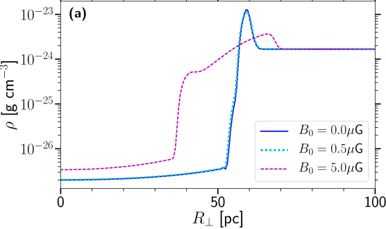
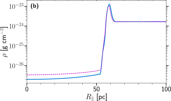
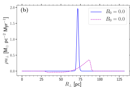
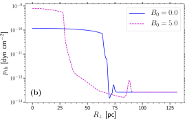
We show the radial profiles at 1 Myr of gas density in Figure 1, perpendicular to the magnetic field, Panel (a), and parallel, (b), for models with and G. With a weak magnetic field G, the evolution of the remnant is very similar to the HD model. With stronger the remnant core is less diffuse, and the slightly less dense remnant shell parallel to the field is coincident with the HD model shell. However, perpendicular to the field the mass profile of the remnant is substantially altered. Mass is more confined within the remnant, but Figure 1 also shows that the SN shockwave propagates faster perpendicular to the magnetic field while carrying less mass at the shock front.
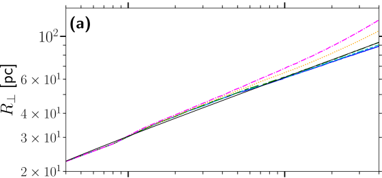
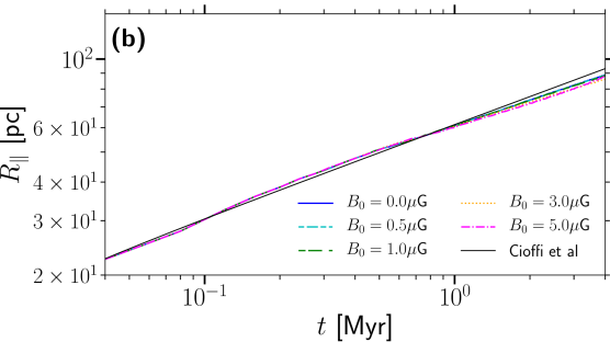
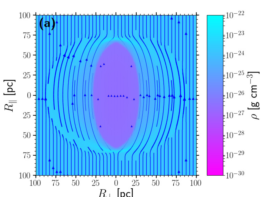
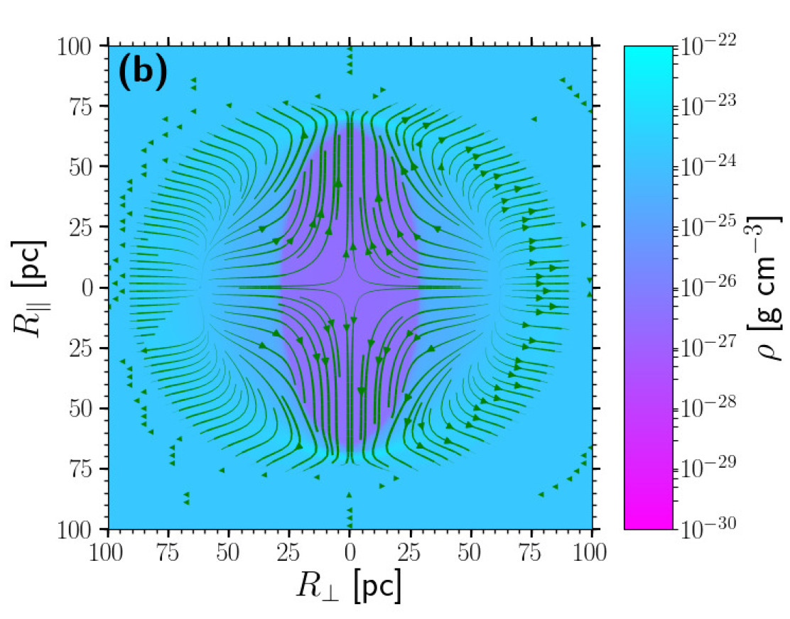
Figure 2(a) shows the shockwave at 2 Myr compressing magnetic field lines to form a dense magnetic collar. Magnetic field is initially evacuated from the core of the remnant. It is evident that the MHD remnant core geometry resembles a prolate spheroid with the polar radius parallel to the magnetic field. The ratio of polar to equatorial radius increases with field strength. In contrast, the remnant shock front forms the surface of an oblate spheroid with equatorial radius perpendicular to the magnetic field. This ratio of polar to equatorial radius decreases with field strength.
Figure 2(b) shows the structure of flows driven by the remnant in a strongly magnetized ambient ISM. The shockwave drives outward flows as expected. We find inward flows of comparable speed to the outward flows. There are retrograde shocks towards the core in all the models, but for the HD and weakly magnetic models these carry negligible mass. For strong the magnetic forces drive inward gas flow from the shell, perpendicular to the magnetic field. As the flow approaches the thermally dominated core, the outward thermal pressure gradient channels the flows parallel to the magnetic field, creating a quadrupolar velocity field between the shockwave and core. In the HD and weakly magnetized remnants, the internal gas flows of the remnant remain radially outward.
By 2 Myr the magnetic field along with some of the gas, has filled almost half the remnant void behind the shock front. This forms an inter-shock region between the core of the remnant and its shell. At even later times the field strength throughout the inter-shock region is close to its original strength. The gas in the core remains hot and diffuse, with magnetic field strength considerably weaker than outside the core.
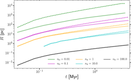
Figure 3 shows the radial evolution of the shockwave for the HD, weakly magnetized and strongly magnetized remnants. The HD remnant has a single characteristic length; the shockwave radius, since the shockwave and core are coupled. This shows good agreement with the analytical solution of Cioffi et al. (1988) for a spherically symmetric model. Shock wave radii are near identical for all models, parallel to the magnetic field. The weakly magnetized remnant behaviour in Figure 3 closely resembles that of the HD remnant. However, perpendicular to the strongly magnetized field the shockwaves diverge from the other profiles near kyr and propagate faster.
Given the ubiquity of magnetic fields in the ISM, it is reasonable to anticipate spheroid morphology to be common in SN remnants. This may be useful in understanding the 3D structure of observed remnants. For example, G351.0-5.4, discovered in de Gasperin et al. (2014) is modelled in first approximation as spherical. This may be reasonable for observations of the shell, which from our models appears only slightly oblate, but misleading for the remnant core. Alternatively, comparisons of gamma-ray and radio data around remnant W44 (Cardillo et al., 2014) indicate a smaller spheroid in gamma-ray emission with polar radius offset from the surrounding spheroid in radio emission, and the presence of magnetic field in the shock G. Complex interaction with molecular clouds and the turbulent ISM affect the morphology of the remnant, but the inter-shock region may also be part of the explanation for the misalignment in the observational profiles.
Modelling the local bubble of the Milky Way with a prolate sphere Alves et al. (2018) find this a reasonable fit even for the magnetic shell. In contrast to our findings, they determine the remnant field to be vertical, out of alignment to the neighbourhood galactic field, and highly anisotropic between North and South. Perhaps, however, an oblate spheroid shell with polar axis parallel to the galactic plane would be an alternative model consistent with the galactic magnetic field.
Any speculation about how our results relate to observational features, are of course at this stage highly tentative. The large scale alignment of magnetic fields in the ISM will surely not be uniform on scales of a few parsecs. The structure of the turbulent magnetic field, the stratification and inhomogeneity of the gas density and temperature, and the turbulent motion of the ambient ISM will be considered in future work, let alone the effects of chemistry and ionization on the observational signatures. Anisotropy of SN remants may of course also arise independent of magnetic effects.
4 Momentum injection
In a typical HD supernova explosion, the propagation of the shock, and subsequent momentum injection into the surrounding medium, is dominated by the thermal pressure gradients, which evacuate mass from the core into the blastwave. In a very similar physical set up to ours, Kim & Ostriker (2015) find the SN terminal momentum injection to be about km s-1, defined by
| (6) |
where is the radial unit vector from the centre of the SN explosion.

We consider this calculation with a modification to account for non-spherical expansion of the SN remnant. The most general approach would be to adopt a tri-axial ellipsoid profile. However in this case, the remnants have two distinct length scales, the SNR radius parallel and perpendicular to the magnetic field, and , respectively. This change produces a bi-axial ellipsoidal remnant, rather than the spherical HD remnants. The ellipsoidal surface is represented by
| (7) |
where and are the directions perpendicular to the magnetic field, and is parallel to the magnetic field. Here represents the remnant shell.222, where , represent contours of the remnant. We now define the normal to the shell as
where
It can be shown that leads to a spherical remnant profile and .
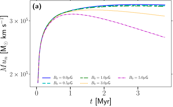
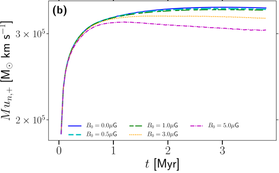
With this definition for applied to Equation (6), we obtain total momentum injection km s-1 for the HD remnant, similar to Kim & Ostriker (2015). we plot the evolution of total momentum for the HD and a range of MHD remnants in Figure 4 (a). As the thermal pressure gradient reduces in the remnant the pressure driven snowplough (PDS) transitions to the momentum conserving snowplough (MCS), as described by Cioffi et al. (1988). It can seen that MCS for the HD model initiates a little later than 2 Myr. A transient MCS occurs much earlier ( Myr) for the strongly magnetized model, subsequentially losing momentum thereafter. As it might be argued that only the outward momentum drives the ISM turbulence we also calculate the outward momentum injection, , which is plotted in Figure 4 (b).
There is a negligible difference between the HD and weak MHD models, but for magnetic field strength above 1 G the momentumn injection diverges significantly from the HD. Contrasting panels (a) and (b) it is evident that although HD remnants feature retrograde shocks, these carry negligible mass back towards the core, while there is significant inward momentum for the strong MHD shocks.
Kim & Ostriker (2015) find that momentum injection ceases within two to three shell-forming times, before the magnetic energy becomes comparable to the thermal energy in the shell. Subsequently, they argue that magnetic effects will not lead to further momentum injection by the remnant. However, from both panels in Figure 4 we find our strong MHD solutions (G) diverge from the HD solution within 200 kyr. These show non-monotonic evolution, reaching a local maximum ( km s-1) after 700 kyr followed by decay. However, outward momentum injection becomes steady after 2 Myr and levels off at km s-1. This suggests that momentum injection is reduced by up to in the presence of a large-scale plane-parallel uniform magnetic field. Evirgen et al. (2019) show that a G dynamo-evolved magnetic field, featuring a strong locally plane-parallel large-scale coherent structure, leads to a decrease in vertical velocity profile. An important contributing factor could be suppression of momentum injection at the SN forcing scale, as seen here.
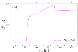
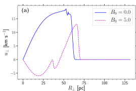
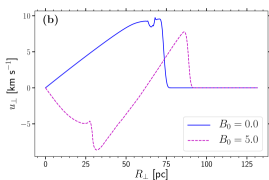
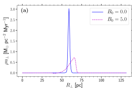
To illustrate what is changing due to the strong MHD we show radial profiles perpendicular to the magnetic field at 1 Myr and 2 Myr in panels (a) and (b), respectively in Figure 5 of the magnetic field strength (top), velocity (centre) and momentum (bottom).
Momentum in the shell of the HD remnant is a factor of 4–6 higher and centered narrowly about the shock front. The MHD shock in all profiles is broader, projectinq both in advance of the HD shock position and including an extended weak inward momentum behind the shock front. Even slowing below 10 km s-1 by 2 Myr the MHD blast wave still remains supersonic. We find that the blast wave remains supersonic even up to 4 Myr. We see from that the magnetic field is swept up into the remnant shell, but that some of this relaxes back towards the core over time.
In order to explore what are the magnetic effects that increase the outward velocity, but inhibit the outward momentum of the MHD remnant in the latter stage, we consider the momentum equation perpendicular to ,
| (8) |
where denotes thermal pressure and refers to diffusive terms in the equation. For our analysis, we are interested in the interaction between the pressure gradient terms and the magnetic tension term on the right hand side of the equation.
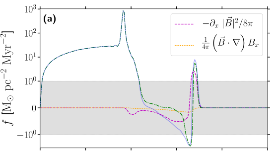
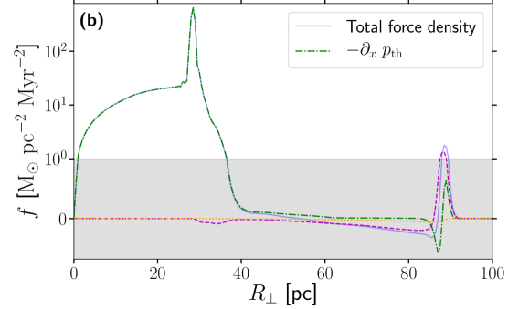
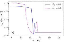
For the strong MHD model Figure 6 shows the forces applying perpendicular to at Myr, Panel (a) and Myr (b). Interestingly, the very large thermal pressure gradient extending through the inner core to about 40 pc at 1 Myr is confined to only 30 pc by 2 Myr. A negative thermal pressure gradient does evolve int he wake of the shock, and this is true also for the HD remnant. However this is too remote from the core to account for its confinement late on. Magnetic effects gradually become dominant at the blastwave, primarily the magnetic pressure gradients, where the outward magnetic pressure gradient is comparable to the thermal gradient at Myr, and 2–3 times greater at Myr. However, the negative pressure gradient in the wake of the shock appears to be the most interesting. The negative force applies throughout the intershock region, between the primary blast wave and the inner thermal pressure front. The magnetic pressure force peels mass away from the remnant shell and drives it inwards along with some of the magnetic field. This broadens the mass shell profile we see from Figure 1 and the magnetic field profile from Figure 5 (top panels) and provides the substantive forces confining the remnant core compared to HD. For most of the pc region by 2 Myr the magnetic pressure gradient dominates the thermal pressure gradient. Magnetic tension is subdominant perpendicular to the magnetic field.
5 Thermodynamics of MHD remnants
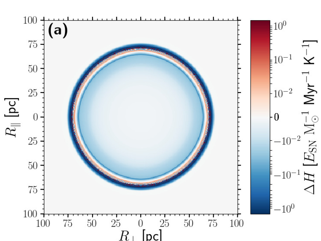
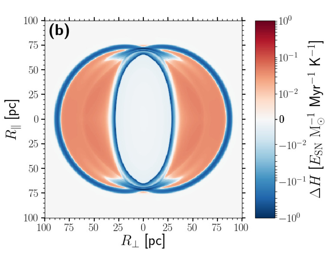
The effect of confinement of the remnant core by the inward magnetic pressure gradient is to reduce adiabatic cooling compared to HD. The system is non-adiabatic, so how does the redistribution of mass in the strong MHD case affect its thermal properties? Snapshots of the net heating, , are presented in Figure 7 for the HD model, Panel (a), and strong MHD model, (b). In the HD and weak MHD models, cooling dominates everywhere in the remnant, except for a thin layer just behind the cooling shell. In the strong MHD model cooling dominates in the confined remnant inner core and shell, but in the inter-shock region perpendicular to the field UV-heating exceeds radiative losses. In Figure 1 (a) this applies for pc.
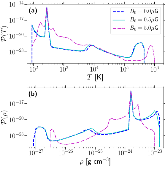
In Figure 8 we show the probability density functions (PDFs) of temperature, (a), and gas density, (b). Each panel features the respective PDFs for models with , 0.5 and 5 G at Myr. All models have identical initial temperature and gas density distributions. The peaks at K and g cm-3 identify the ambient ISM. For the HD model and model with G, the differences in the PDFs are otherwise also negligible. The other local maxima identify the cold remnant shell ( cm-3, K), the hot diffuse core ( cm-3, K), and the accumulation of thermally stable warm gas ( cm-3, K).
However, with the strong magnetic field the peak temperatures representing the remnant shell and the remnant cores are hotter and more dense. Its magnetically confined hot gas has a smaller fractional volume. Hot gas in all models cools slowly, due to the low density, but the strong MHD hot gas cools due to radiative losses relatively faster due to its slightly higher density. It nevertheless remains hotter, because the adiabatic cooling is reduced. The strong MHD model has almost identical temperature distribution in the range K, although more dense.
Most unexpected is the large proportion of gas in the MHD model persisting around 1000 K. In the HD model below the local maximum at K is thermally unstable, with gas cooling rapidly to and accumulating at about 90, K, where the cooling function, , smoothly truncates. However with a strong magnetic field much of the gas in the remnant persists in this thermally unstable range, the cold peak sustained about 200 K and cm-3. filling fraction fractional volume, we went to some lengths in paper 1 to define the three methods of measuring fraction by phase, so let’s keep the label precise. Delete when OK The high fractional volume of thermally unstable higher density gas in the MHD model is explained by the revised balance of heating, , and cooling processes, in the inter-shock region illustrated in Figure 7 (b).
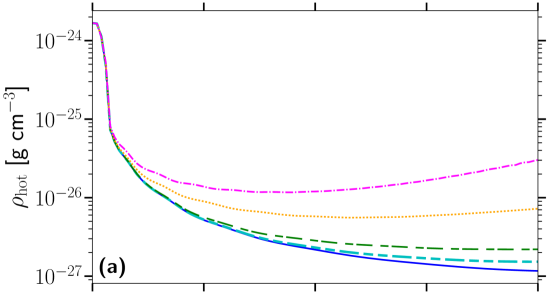
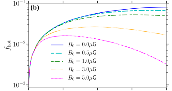
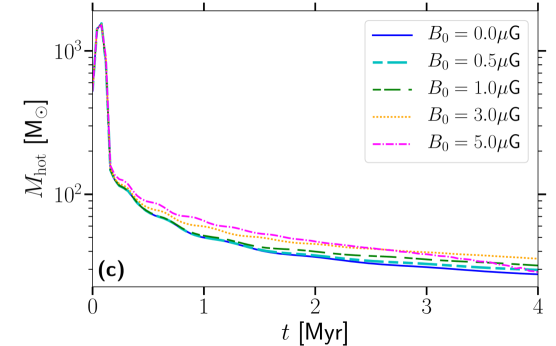
Magnetic confinement of hot gas in the remnant is indicated strongly by the increasing mean hot gas density plotted in Figure 9 (a) and decreasing fractional volume from Figure 9 (b) of hot gas in strongly magnetized remnants. This effect has also been found in larger-scale simulations of the ISM (Evirgen et al., 2017, 2019). The residual total mass of hot gas deposited into the ISM may be 20–40% greater in the strong MHD remnant as depicted in Figure 9 (c).
In Figure 10 we show radial profiles perpendicular to the magnetic field at 1 Myr (a) and 2 Myr (b), for temperature (top) and thermal pressure (bottom) for the HD and strong MHD remnants. This illustrates the higher temperature in the MHD core, but smaller fractional volume.
6 Residual SN energy injection
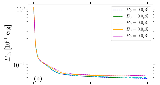
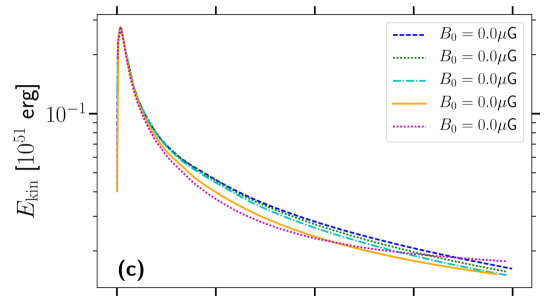
Inspection of the momentum injection indicates the magnetic field can reduce the residual momentum appled to the ISM by an SN remnant. The increased mass of hot gas, on the other hand and reduced effect of non-adiabatic cooling within an MHD remnant invites the question how are the energetics of the ISM affected by a strong magnetic field? The time evolution of residual SN total energy and each contribution to the energy are plotted in Figure 11.
Panel (a) shows that a significant increase in residual total energy occurs with strong MHD even within 1 Myr of the supernova explosion.
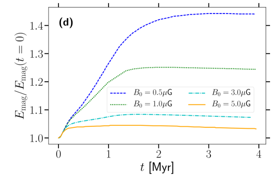
From Panel (b) we see that the presence of large-scale magnetic fields retains more residual thermal energy, while Panel (c) shows that kinetic energy in the MHD remnants is lost more quickly. Beyond 3 Myr the strong MHD residual kinetic energy can persist more effectively than HD, would likely be subsumed by the ambient ISM turbulence by this time. For all MHD models there is a modest linear amplification of the magnetic field trhough compression and tangling (Panel (d)). So the net contributions of thermal and magne sutic energy mean that the MHD shocks in fact induce a greater total residual energy into the ISM than HD alone.

| Time [Myr] | [G] | ||||
|---|---|---|---|---|---|
| 0 | 0.5 | 1.0 | 3.0 | 5.0 | |
| 0.25 | 16.2 | 16.2 | 16.5 | 17.2 | 18 |
| 0.5 | 10.2 | 10.3 | 10.4 | 11.4 | 12.4 |
| 1.0 | 5.4 | 5.5 | 5.9 | 6.7 | 7.7 |
| 2.0 | 2.9 | 3.1 | 3.5 | 4.6 | 5.5 |
| 4.0 | 1.3 | 1.6 | 2.0 | 3.5 | 4.2 |
The effects are tabulated for each model at various times throughout their evolution in Table 1. Differences emerge with HD within 250 kyr of the SN explosion for strong MHD models. The G and G models retain 6% and 11% more energy, rising to 10% and 20% within 500 kyr. The HD simulation retains of SN energy by the end of the simulation. As magnetic field strength increases, the SN energy retained by the system increases, reaching for G.
7 Critical magnetic field strength
Any qualitative differences between the HD and MHD remnants must arise from effects due to the Lorentz force. Inspection of the evolution of magnetic tension reveals this to be negligible, relative to the magnetic and thermal pressure gradients. The maximal tension forces apply in the remnant shell nearest the polar axis of the remnant.
Therefore, modification to momentum injection relies on the interacting radial pressure gradients, particularly where . In the blast wave the magnetic gradient will grow due to compression. The stronger the ambient field, the earlier the magnetic gradient in the shell and in its wake will acquire a critical strength sufficient to significantly modify the remnant evolution. The MHD shell begins to shed mass into its wake, compared to HD as early as 200 kyr for G, 320 kyr for 3G and 920 kyr for 1G. The leading shock outstrips the HD model at 440, 560 and 1560 kyr, respectively. From both panels in Figure 6 throughout the inter-shock region we have
but when the MHD shock profiles start to diverge from HD this ratio locally is still much less than 1. A reasonable criteria for identifying the critical large-scale magnetic field strength may be to assume plasma-1. Hence, , where ; is the Boltzmann constant, and denotes temperature.
For these simulations the ambient ISM has cm-3 and K. Thus, the gas is in thermal equilibrium with radiative cooling balancing UV heating. We show in Appendix C that the results are not sensitive to the initial ambient temperature, which cools very quickly to the equilibrium temperature to evolve with the same remnant properties. We obtain G. G does lead to marginal MHD effects. In agreement with Hanayama & Tomisaka (2006), we find that significant change to the nature of the remnant is seen for G. However, the effect of cooling and heating processes are highly nonlinear functions of density, so we shall explore how to explain critical field strength with various ambient ISM densities and magnetic field configurations.
8 Summary
The merger of the remnant shell with the surrounding gas depends on a number of factors, including but not limited to, ambient sound speed, homogeneity (or inhomogeneity) of the ambient gas density structures, and interaction with other shocks in a turbulent, highly compressible and typically inhomogeneous interstellar medium. However, the emergence of differences in energy retention, directly linked to the presence of large-scale magnetic fields, suggests that the efficiency with which the surrounding gas extracts energy from SN remnants is modified by magnetic fields.
A plane-parallel, micro-gauss strength magnetic field changes the aspect ratio of SN remnants. The shockwave through the ambient ISM propagates faster perpendicular to the magnetic field. Figure 15 of Caunt & Korpi (2001) show a similar MHD remnant expanding faster perpendicular to the plane-parallel field. This is also identified by Ferriere et al. (1991) in the context of a superbubble blast wave. They also report that the MHD blast is faster in the parallel direction than for HD. Conversely, the hot diffuse remnant core is magnetically confined into a prolate spheroid with pole aligned to the field. Hanayama & Tomisaka (2006); Kim & Ostriker (2015) also find that expansion of the core is inhibited perpendicular to a plane-parallel magnetic field.
Both effects are caused by the magnetic pressure gradients perpendicular to the magnetic field. In the adiabatic and pressure driven phases of the blast wave expansion, while magnetic forces are weak relative to the explosive forces, magnetic field is expelled from the core and compressed into the shell. Some energy from the thermally driven outward shock is stored in the highly compressed field at the remnant shell, to be released through the magnetic pressure gradient in the late MHD shock. Compression also generates an increasingly negative magnetic pressure gradient just behind the shell, ultimately injecting momentum inwards.
In similar simulations, which focus on the early (up to 400 kyr) stage of SN evolution, Kim & Ostriker (2015) conclude that momentum injection by an SN remnant is unaffected by the presence of a plane-parallel magnetic field. They suggest magnetic fields will not affect momentum injection, because they do not become comparable to thermal effects before the remnant enters the momentum-conserving phase. In contrast we do find for G a substantial effect on outward momentum injection already within 500 kyr, which could be reduced by up to 10% in the presence of a large-scale magnetic field. Given the role of SN in driving both turbulent and large-scale flows (such as galactic winds), such a reduction in momentum injection could have a noticeable effect on gas dynamics within galaxies.
MHD effects also lead to confinement of the hot core and a more dense inter-shock region. UV-heating exceeds radiative losses in this region and, combined with the magnetic broadening of the shock front, inhibits the formation of cold gas, compared to HD. This results in a region of thermally unstable warm gas, which will eventually merge with the surrounding gas. In contrast to the reduced momentum injection the residual energy of an MHD SN remnant can be up to 40% greater within 1 Myr. This, however, corresponds to a reduced fractional volume of hot gas, an effect also noted by Evirgen et al. (2019). Even though we obtain this result in an idealized numerical setup, Evirgen et al. (2019) find that hot gas becomes more dense in numerical simulations of the local Galaxy, as the magnetic field reaches G strength with a strong large-scale component. These numerical simulations feature highly inhomogeneous gas density, compressible turbulence and a multi-phase ISM structure. Thus, it is plausible that our remnant-scale simulations may relate to magnetic effects found in more sophisticated numerical models.
In its early stages the presence of a magnetic field has negligible effect on SN remnant evolution, and this is consistent with the results of Kim & Ostriker (2015). However, as the magnetic shell forms increasingly strong local pressure gradients the dynamics alter markedly. For sufficiently weak magnetic fields this may evolve so late that the blast wave has already merged with the ISM and it remains dynamically insignificant. For stronger fields the magnetic retrograde shock and late MHD shock occur sufficiently early to alter remnant momentum injection and structure. For gas density cm-3, we find the critical field strength to correspond to plasma- in the ambient ISM. The magnetic confinement and late MHD shock occur earlier and are stronger as increases within the range G considered. With respect to structure, this is consistent with Hanayama & Tomisaka (2006), who find notiecable magnetic confinement of the remnant interior for G, and Kim & Ostriker (2015) for G.
Magnetic fields in the ISM are not uniform as applied in these models and planned studies shall include the effects of turbulent structure of the magnetic field and a range of ambient ISM density. Nevertheless, it is widely observed that spiral galaxies have a large-scale, coherently structured magnetic field of strength in the range –G (Beck, 2001; Tabatabaei et al., 2008; Fletcher et al., 2011). Thus, it is plausible that SN remnants evolve subject to the magnetic effects described here, which could have significant implications on pressure support, mass loading of the galactic halo, and generally the multiphase and vertical structure of the ISM.
Acknowledgements
We would like to thank the referee for their insightful feedback, which has helped improve both the scientific content and narrative of this Paper.
The work has been performed under the Project HPC-EUROPA3 (INFRAIA-2016-1-730897), with the support of the EC Research Innovation Action under the H2020 Programme; in particular, CCE gratefully acknowledges the support of the Department of Computer Science at Aalto University and the computer resources and technical support provided by the CSC HPC Centre in Finland. FAG acknowledges financial support of the Grand Challenge project SNDYN and GDYNS, CSC-IT Center for Science Ltd. (Finland) and the Academy of Finland Project 272157.
References
- Alves et al. (2018) Alves, M. I. R., Boulanger, F., Ferrière, K., & Montier, L. 2018, A&A, 611, L5, doi: 10.1051/0004-6361/201832637
- Beck (2001) Beck, R. 2001, Space Sci. Rev., 99, 243
- Cardillo et al. (2014) Cardillo, M., Tavani, M., Giuliani, A., et al. 2014, A&A, 565, A74, doi: 10.1051/0004-6361/201322685
- Caunt & Korpi (2001) Caunt, S. E., & Korpi, M. J. 2001, A&A, 369, 706, doi: 10.1051/0004-6361:20010157
- Chevalier (1974) Chevalier, R. A. 1974, ApJ, 188, 501, doi: 10.1086/152740
- Chevalier & Clegg (1985) Chevalier, R. A., & Clegg, A. W. 1985, Nature, 317, 44, doi: 10.1038/317044a0
- Cioffi et al. (1988) Cioffi, D. F., McKee, C. F., & Bertschinger, E. 1988, ApJ, 334, 252, doi: 10.1086/166834
- de Gasperin et al. (2014) de Gasperin, F., Evoli, C., Brüggen, M., et al. 2014, A&A, 568, A107, doi: 10.1051/0004-6361/201424191
- Evirgen et al. (2017) Evirgen, C. C., Gent, F. A., Shukurov, A., Fletcher, A., & Bushby, P. 2017, MNRAS, 464, L105, doi: 10.1093/mnrasl/slw196
- Evirgen et al. (2019) Evirgen, C. C., Gent, F. A., Shukurov, A., Fletcher, A., & Bushby, P. J. 2019, in press, arXiv:1903.10263. https://arxiv.org/abs/1903.10263
- Ferriere et al. (1991) Ferriere, K. M., Mac Low, M.-M., & Zweibel, E. G. 1991, ApJ, 375, 239, doi: 10.1086/170185
- Fletcher et al. (2011) Fletcher, A., Beck, R., Shukurov, A., Berkhuijsen, E. M., & Horellou, C. 2011, MNRAS, 412, 2396, doi: 10.1111/j.1365-2966.2010.18065.x
- Gent (2012) Gent, F. A. 2012, PhD thesis, Newcastle University School of Mathematics and Statistics
- Gent et al. (2019) Gent, F. A., Mac Low, M.-M., Käpylä, M. J., Sarson, G. R., & Hollins, J. F. 2019, GAFD, in press, arXiv:1806.01570. https://arxiv.org/abs/1806.01570
- Gent et al. (2013) Gent, F. A., Shukurov, A., Fletcher, A., Sarson, G. R., & Mantere, M. J. 2013, MNRAS, 432, 1396, doi: 10.1093/mnras/stt560
- Girichidis et al. (2016) Girichidis, P., Walch, S., Naab, T., et al. 2016, MNRAS, 456, 3432, doi: 10.1093/mnras/stv2742
- Hanayama & Tomisaka (2006) Hanayama, H., & Tomisaka, K. 2006, ApJ, 641, 905, doi: 10.1086/500527
- Hawley et al. (1984) Hawley, J. F., Smarr, L. L., & Wilson, J. R. 1984, ApJ, 277, 296, doi: 10.1086/161696
- Jun & Norman (1996) Jun, B.-I., & Norman, M. L. 1996, The Astrophysical Journal, 472, 245
- Kim & Ostriker (2015) Kim, C.-G., & Ostriker, E. C. 2015, ApJ, 802, 99, doi: 10.1088/0004-637X/802/2/99
- Mac Low & Klessen (2004) Mac Low, M.-M., & Klessen, R. S. 2004, Reviews of Modern Physics, 76, 125, doi: 10.1103/RevModPhys.76.125
- McKee & Ostriker (1977) McKee, C. F., & Ostriker, J. P. 1977, ApJ, 218, 148, doi: 10.1086/155667
- Murray et al. (2005) Murray, N., Quataert, E., & Thompson, T. A. 2005, ApJ, 618, 569, doi: 10.1086/426067
- Sarazin & White (1987) Sarazin, C. L., & White, III, R. E. 1987, ApJ, 320, 32, doi: 10.1086/165522
- Sedov (1959) Sedov, L. I. 1959, Similarity and Dimensional Methods in Mechanics
- Slavin & Cox (1992) Slavin, J. D., & Cox, D. P. 1992, ApJ, 392, 131, doi: 10.1086/171412
- Sod (1978) Sod, G. A. 1978, Journal of Computational Physics, 27, 1, doi: 10.1016/0021-9991(78)90023-2
- Spitzer (1978) Spitzer, L. 1978, Physical processes in the interstellar medium, doi: 10.1002/9783527617722
- Tabatabaei et al. (2008) Tabatabaei, F. S., Krause, M., Fletcher, A., & Beck, R. 2008, A&A, 490, 1005, doi: 10.1051/0004-6361:200810590
- Taylor (1950) Taylor, G. 1950, Proceedings of the Royal Society of London Series A, 201, 159, doi: 10.1098/rspa.1950.0049
- Tomisaka (1998) Tomisaka, K. 1998, MNRAS, 298, 797, doi: 10.1046/j.1365-8711.1998.01654.x
- Tomisaka et al. (1981) Tomisaka, K., Habe, A., & Ikeuchi, S. 1981, Ap&SS, 78, 273, doi: 10.1007/BF00648941
- Wolfire et al. (1995) Wolfire, M. G., Hollenbach, D., McKee, C. F., Tielens, A. G. G. M., & Bakes, E. L. O. 1995, ApJ, 443, 152, doi: 10.1086/175510
- Yadav et al. (2017) Yadav, N., Mukherjee, D., Sharma, P., & Nath, B. B. 2017, MNRAS, 465, 1720, doi: 10.1093/mnras/stw2522
- Zirakashvili & Ptuskin (2008) Zirakashvili, V. N., & Ptuskin, V. S. 2008, The Astrophysical Journal, 678, 939
Appendix A Identifying numerical effects through 1D shock-tube tests
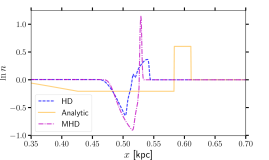
To verify that the significant qualitative effects we identify from the MHD blast waves are attributable to the physics rather than the numerics, we examine the impact of employing artificial diffusivities compared to the impact of a magnetic field on the solutions. For numerical economy we use a set of 1D shock-tube tests. The numerical solutions for adiabatic shocks with parameters relevant to SN blast waves are compared to the system originally described by Sod (1978), and its exact analytical solution derived by Hawley et al. (1984). We extend the analysis applied to the HD solutions of Gent et al. (2019) to consider specifically whether MHD or numerical effects account for the differences in the MHD solutions
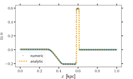
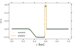
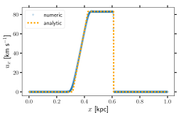
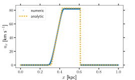
Figure 12 shows that for an adiabatic shock the HD numerical solution reliably produces the analytic solution. Even the MHD solution has only marginally enhanced gas density in the shock. Hence, neither numerical parameters nor the presence of the magnetic field have a significant effect on the solution in the adiabatic system, and this is consistent with most previous assessments.
We next consider the effect radiative cooling and UV heating on the shock-tube solution. In Figure 13 the non-adiabatic HD and MHD numerical solutions are contrasted to the adiabatic analytic solution. We do not have a non-adiabatic analytic shock-tube solution.
The inclusion of cooling and heating processes has a noticeable effect on both HD and MHD shock tubes; both shocks propagate more slowly through the ambient gas. This is not unexpected, since these processes extract energy which would otherwise be used up in the propagation of the shock. We note that the MHD shock propagates faster than the HD shock, as also seen in the 3D simulations presented in this Paper. The gas density behind the shock tube is higher than the standard set up for both HD and MHD shock tubes with cooling and heating. However, as seen in the 3D simulations, the gas density is higher behind the shock for the MHD shock tube. In addition, the shock density is lower in the MHD shock. This is evidence that the nonlinear interaction between the MHD and non-adiabatic effects is a significant factor in the divergence of the HD and MHD solutions.
For the 1D shock-tube tests an artificial shock-dependent mass diffusion is unnecessary, but we include it in these experiments to verify that its inclusion in SN-driven turbulence simulations does not induce excessive numerical diffusion. We consider a range of mass shock diffusivity .
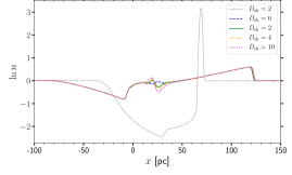
From Figure 14 we show that adding mass diffusion, while providing numerical stability, produces a minor quantitative difference in the gas density shock profile. The profiles are otherwise qualitatively the same and the contrast with the HD profile is clearly down to the presence of the magnetic effects rather than the mass diffusion. A remaining concern is that the broadening of the mass profile in the MHD blast wave may arise from the high value of the viscosity, with kpc km s-1 in the 3D SN blast waves. Although the estimates of microscopic viscosity in the real ISM are orders of magnitude lower, the viscosity in the model represents instead a turbulent viscosity. To model turbulence we require this dissipation scale applies above the grid scale, but sufficiently below the SN forcing scale to accurately capture the energy spectrum down to the smallest scales of interest in the model. We vary with kpc km s-1 and kpc km s-1 for the non-adiabatic 1D shock-tube tests. This also effectively changes the magnetic Prandtl number in the MHD simulations, defined as , which yields . Given that in these solutions km s-1, we also have
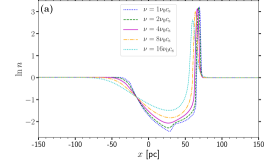
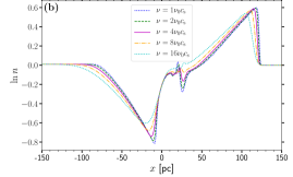
Some resulting density profiles are shown in Figure 15. Both HD and MHD are affected similarly by increasing viscosity. The shock front does not propagate as fast for higher values of and the region behind the shock is smoothed. However both HD and MHD shocks are not affected qualitatively as viscosity is increased. The difference between the HD and MHD solutions cannot be explained by high diffusivity.
Appendix B Changing the ambient gas density
There is a significant change to the HD SN evolution when a moderately strong uniform magnetic field is embedded in the ambient ISM. We conclude that this is in part due to the alteration of the radiative cooling and UV-heating characterstics in response to the retrograde flow of gas into the remnant. The cooling and heating profile of the ISM is highly sensitive to the gas density and temperature. We would like to explore the response to varying ambient ISM density in the 3D MHD SN remnant evolution in future work, but here we perform a preliminary low budget experiment with 1D shock-tube tests of varying ambient gas density. We apply ambient gas number density, cm-1 to assess whether the magnetic effects described in this Paper may be generalised beyond 1 cm-3. The range of densities chosen reflect the range from diffuse, hot gas to dense, cold gas. The initial entropy of the ambient gas is adjusted such that the ambient temperature remains constant with net heating at zero appropriate to the initial gas density. Specfic gas entropy is expressed as
with and expressed in dimensionless code units, is the adiabatic index, and is the specific heat capacity. Some initial configuration is represented by , and,
We change the gas density such that , where , but keep the temperature constant, such that .
The two entropies, the new entropy can be related to the old value :
| (B1) |
We use this expression to change gas density while keeping initial temperature constant. In Figure 16, we present the time profiles of distance travelled by the non-adiabatic shock (analogous to remnant shell radius) for a range of ambient gas densities. The effect of the magnetic field is measured by the difference between the profiles for HD and MHD shocks of identical ambient gas density. As in the 3D SN simulations, divergence of the MHD shock profile from the HD profile indicates the effect of magnetic field. We find that the effect of the magnetic field increases as the ambient density becomes more diffuse, due to decreasing plasma-. Magnetic effects are seen for all ambient densities apart from cm-3. Magnetic effects appear earlier in the lower ambient gas densities.
Appendix C Temperature of the ambient gas
In our simulations, we set the ambient gas temperature K, to ensure that the SN explosion is set off with an ambient medium in thermal equilibrium. This particular temperature is chosen as the radiative cooling and UV-heating balance each other, yielding zero net heating in the ambient gas. However, K is a more typical temperature for the ISM, particularly for ambient gas number density , cm-3. Using this low density would substantially increase the numerical domain size and computational expense. We, therefore, run a 3D SN simulation identical to the MHD remnant simulation with G and cm-3, but with K.
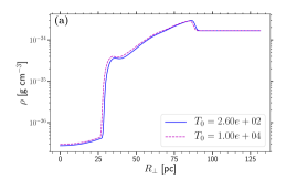
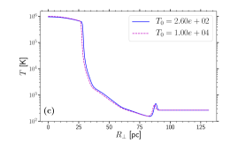
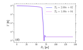
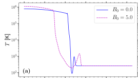
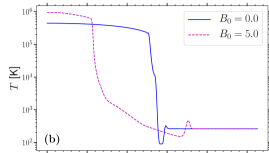
Figure 17 shows that the radial profiles of gas density and temperature are qualitatively identical and quantitatively very similar at 2 Myr. The re-distribution of mass from the shell to the interior of the remnant occurs in both models, forming the inter-shock region between the magnetically confined diffuse core and the shell, in the direction perpendicular to the magnetic field.
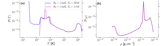
Moreover, the PDFs of gas temperature and density provided in Figure 18, which are given at 400 kyr, 1 Myr and 2 Myr, show that the temperature distributions converge despite the different initial temperatures. The hottest gas is identical from an early stage, as it is injected by the SN remnant, irrespective of the initial ambient gas temperature. In the cooler range, the modal temperature of the gas, for the K model, gradually converges to the K model, for which the ambient gas is in thermal equilibrium from the beginning of the simulation. We see that the lower peak in the temperature PDF, corresponding to the ambient ISM, cools over time, reaching thermal equilibrium peak by 2 Myr. Evidently, the difference to the thermal pressure gradient form the higher temperature is negligible.
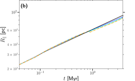
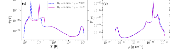
Figure 19 shows the evolution of remnant radius perpendicular and parallel to the magnetic field. Panel (b) shows that the HD model and both MHD models agree with the Cioffi et al. (1988) analytical solution. The radius of the K MHD model is marginally (within 2 pc) less than the K model. Panel (a) shows that both MHD models have an identical time profile for the radius perpendicular to the magnetic field.