11email: [a.i.v.goethem|b.speckmann|k.a.b.verbeek]@tue.nl
Optimal Morphs
of Planar Orthogonal Drawings II
Abstract
Van Goethem and Verbeek [11] recently showed how to morph between two planar orthogonal drawings and of a connected graph while preserving planarity, orthogonality, and the complexity of the drawing during the morph. Necessarily drawings and must be equivalent, that is, there exists a homeomorphism of the plane that transforms into . Van Goethem and Verbeek use linear morphs, where is the maximum complexity of the input drawings. However, if the graph is disconnected their method requires linear morphs. In this paper we present a refined version of their approach that allows us to also morph between two planar orthogonal drawings of a disconnected graph with linear morphs while preserving planarity, orthogonality, and linear complexity of the intermediate drawings.
Van Goethem and Verbeek measure the structural difference between the two drawings in terms of the so-called spirality of relative to and describe a morph from to using linear morphs. We prove that linear morphs are always sufficient to morph between two planar orthogonal drawings, even for disconnected graphs. The resulting morphs are quite natural and visually pleasing.
1 Introduction
Continuous morphs of planar drawings have been studied for many years, starting as early as 1944, when Cairns [7] showed that there exists a planarity-preserving continuous morph between any two (compatible) triangulations that have the same outer triangle. These results were extended by Thomassen [10] in 1983, who gave a constructive proof of the fact that two compatible straight-line drawings can be morphed into each other while maintaining planarity. The resulting algorithm to compute such a morph takes exponential time (just as Cairns’ result). Thomassen also considered the orthogonal setting and showed how to morph between two rectilinear polygons with the same turn sequence. For planar straight-line drawings the question was settled by Alamdari et al. [1], following work by Angelini et al. [3]. They showed that uni-directional linear morphs are sufficient to morph between any compatible pair of planar straight-line drawings of a graph with vertices while preserving planarity. The corresponding morph can be computed in time.
In this paper we consider the orthogonal setting, that is, we study planarity-preserving morphs between two planar orthogonal drawings and with maximum complexity , of a graph . Here the complexity of an orthogonal drawing is defined as the number of vertices and bends. All intermediate drawings must remain orthogonal, as to not disrupt the mental map of the reader. This immediately implies that the results of Alamdari et al. [1] do not apply, since they do not preserve orthogonality. Biedl et al. [5] described the first results in this setting, for so-called parallel drawings, where every edge has the same orientation in both drawings. They showed how to morph between two parallel drawings using linear morphs while maintaining parallelity and planarity. More recently, Biedl et al. [4] showed how to morph between two planar orthogonal drawings using linear morphs, while preserving planarity, orthogonality, and linear complexity. Van Goethem and Verbeek [11] improved this bound further to linear morphs for a connected graph . This bound is tight, based on the lower bound for straight-line graphs proven by Alamdari et al. [1].
If the graph is disconnected, then Aloupis et al. [2] show how to connect in a way that is compatible with both and while increasing the complexity of the drawings to at most . They also prove a matching lower bound if has at most connected components. This directly implies that Van Goethem and Verbeek require linear morphs for a disconnected graph .
Paper Outline. We show how to refine the approach by Van Goethem and Verbeek [11] to also morph between two planar orthogonal drawings of a disconnected graph using linear morphs while preserving planarity, orthogonality, and linear complexity. In Section 2 we describe the necessary background. In particular, we discuss wires: equivalent sets of horizontal and vertical polylines that capture the - and -order of the vertices in and . The spirality of these wires guides the morph. In Section 3 we show how to find sets of wires with linear spirality for equivalent orthogonal planar drawings and of a disconnected planar graph . Van Goethem and Verbeek are agnostic of the connectivity of the graph once they create the wires. Hence, using the wires constructed in Section 3, we can directly apply their approach to disconnected graphs.
In the remainder of the paper we show how to “batch” intermediate morphs. We argue solely based on sets of wires, hence the results apply to both connected and disconnected graphs. In particular, in Section 4 we show how to combine all intermediate morphs that act on segments of spirality into one single linear morph. Hence we need only linear morphs to morph from to . However, the rerouting and simplification operations introduced by van Goethem and Verbeek to lower the intermediate complexity are not compatible with batched linear morphs and hence intermediate drawings have complexity of . In Section 5 we present refined versions of both operations which allow us to maintain linear complexity through the linear morphs. The initial setup for these operations costs one additional morph, for a total of linear morphs that preserve planarity, orthogonality, and linear complexity. We implemented our algorithm and believe that the resulting morphs are natural and visually pleasing111See https://youtu.be/n0ZaPtfg9TM for a short movie.. We restrict our arguments to proof sketches, full proofs can be found in the appendix.
2 Preliminaries
Orthogonal drawings. A drawing of a graph is a mapping from every vertex to a unique point in the Euclidean plane and from each edge to a simple curve in the plane starting at and ending at . A drawing is planar if no two curves intersect in an internal point, and no vertices intersect a curve in an internal point. A drawing is orthogonal if each edge is mapped to an orthogonal polyline consisting of horizontal and vertical segments meeting at bends. In a straight-line drawing every edge is represented by a single line-segment. Two planar drawings and are equivalent if there exists a homeomorphism of the plane that transforms into .
We consider morphs between two equivalent drawings of a graph . To simplify the presentation, we assume that both drawings are straight-line drawings with vertices. If this is not the case then we first unify and . We subdivide segments, creating additional virtual bends, to ensure that every edge is represented by the same number of segments in and . Next, we replace all bends with vertices. All edges of the resulting graph are now represented by straight segments (horizontal or vertical) in both and .
A linear morph of two drawings and can be described by a continuous linear interpolation of all vertices and bends, which are connected by straight segments. For each there exists an intermediate drawing where each vertex is drawn at ( and ). A linear morph maintains planarity (orthogonality, linear complexity, resp.), if every intermediate drawing is planar (orthogonal, of linear complexity, resp.).
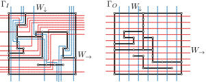
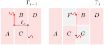
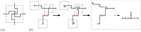
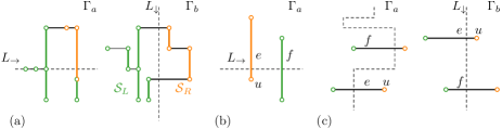
Wires. Following van Goethem and Verbeek [11] we use orthogonal polylines called wires as the main tool to determine the morph. Wires consist of horizontal or vertical segments called links. We use two sets of wires to capture the horizontal and vertical order of the vertices in and . The lr-wires traverse the drawings from left to right, and the tb-wires traverse the drawings from top to bottom. Since the horizontal and vertical order of the vertices in are guiding our morph, the wires and are simply horizontal and vertical lines in separating consecutive vertices in the - and -order (only if their - or -coordinates are distinct). and are equivalent, hence there exist wires in that are equivalent to the wires in : there is a one-to-one matching between the wires of and such that matching wires partition the vertices identically, and cross both the segments of the drawings and the links of the other wires in the same order (see Fig. 1). Any such two wires in do not cross if they are from the same set and cross exactly once otherwise.
Van Goethem and Verbeek use the spirality of wires as a measure for the distance to (where all wires are straight lines of spirality zero). Spirality is a well-established measure in the context of orthogonal drawings and is frequently used for bend-minimization [6, 8, 9]. Specifically, let be a lr-wire, and be the links ordered along . Let be the orientation of the bend from to , where for a left turn, for a right turn, and otherwise. The spirality of a link is defined as . A maximum-spirality link is any link with the largest absolute spirality. The spirality of a wire is the maximum absolute spirality of any link in the wire, the spirality of a set of wires is the maximum spirality of any wire in the set.
The spirality of a drawing is not well defined: it is always relative to another drawing and the straight-line wires induced by . Furthermore, there are possibly multiple sets of matching wires in for the straight-line wires in . Still, whenever the drawing and the matching set of wires in are clear from the context, then by abuse of notation we will speak of the spirality of . Unless stated otherwise, we always consider spirality relative to .
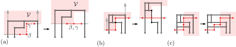
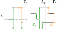
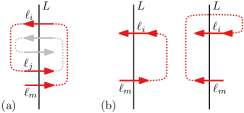
Slides. Biedl et al. [4] introduced slides as a particular type of linear morph that operates on the segments of the drawing. Van Goethem and Verbeek [11] extended this concept to wires. Slides on wires may be accompanied by the insertion or deletion of bends in the drawing. In the following we exclusively consider slides on wires. A zigzag consists of three consecutive links of a wire and two bends and that form a left turn followed by a right turn or vice versa. Consider the horizontal zigzag with bends and in Figure 2(a). Let be the set of vertices and bends of both the drawing and the wires that are (1) above or at the same height as and strictly to the left of , (2) that are strictly above , and (3) . The corresponding region is shaded in Figure 2. A zigzag-eliminating slide is a linear morph that straightens a zigzag on a wire by moving all vertices and bends in up by the initial distance between and .
By definition, wires do not contain any vertices or bends of the drawing or other wires. However, the center link might be crossed by a segment of the drawing or a link of a wire in the other set (see Fig. 2(b) for a crossing with a segment of the drawing). In this case we introduce two virtual bends in the segment or the link on the crossing and symbolically offset one to the right and one to the left. The left bend is thus included in while the right bend is not. We can prevent that multiple segments or links cross using so-called bend-introducing slides as discussed in [11] (see Fig. 2(c)).
3 Linear morphs for disconnected graphs
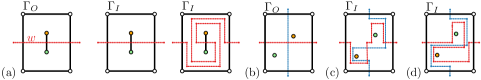
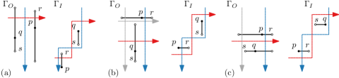
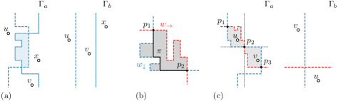
Let and be two equivalent planar orthogonal drawings of a disconnected graph . For a connected graph there is a unique homotopy class in that contains all possible wires that match a given wire from . This statement does not hold for disconnected graphs: there might be more than one homotopy class in that matches (see Fig. 3(a)). If we choose homotopy classes independently for the wires in then their union might not be equivalent to the set of wires in , for example, wires might cross more than once (see Fig. 3(c)).
Below we show that we can choose homotopy classes for the wires in incrementally, first for the lr-wires and then for the tb-wires, while maintaining the correct intersection pattern and hence equivalence with . For each of the resulting equivalence classes we add the shortest wire to the set of wires. It remains to argue that the resulting set of wires has spirality despite the interdependence of the homotopy classes and the fact that the arrangement of drawing and wires can have super-linear complexity (which invalidates the proofs from [11]). Below we consider only , analogous results hold for .
Lemma 1
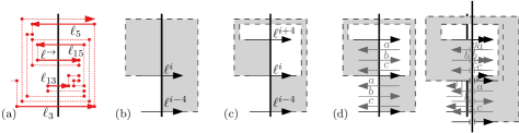
For each right-oriented link of a wire with positive (negative) spirality there exists a vertical line and a subsequence of links of crossing , such that the absolute spiralities of the links in sequence are , and when ordered top-to-bottom (bottom-to-top) along form the sequence .
Figure 4(a) illustrates Lemma 1. Let be a right-oriented link on a wire and w.l.o.g. let be the spirality of . Further, let be a vertical line through and a subsequence from with the properties guaranteed by Lemma 1. Finally, let be the unique link with spirality in . We define the -core for (for and ) as the region enclosed by the wire from the intersection between and to the intersection between and and the straight line segment along connecting them (see Fig 4(b)). We define the -layer for (for and ) as the difference of the -core and the -core (see Fig 4(c)).
Lemma 2
An equivalent set of lr-wires with spirality exists.
Proof
(Sketch) We prove by induction that we can add a new lr-wire with spirality . If a wire has layers, then we can argue via shortcuts (see Fig. 4(d)) that was not shortest with respect to previously inserted wires.
Lemma 3
An equivalent set of wires with spirality exists.
Proof
Theorem 3.1
Let and be two unified planar orthogonal drawings of a (disconnected) graph . We can morph into using linear morphs while maintaining planarity and orthogonality.
4 Combining intermediate linear morphs
The proof of Theorem 3.1 implies a morph between two unified planar orthogonal drawings and exists using linear morphs, where is the spirality of . In this section we show how to combine consecutive linear morphs into a total number of only linear morphs, while maintaining planarity and orthogonality.
The morphs we describe can be encoded by a sequence of drawings, starting with and ending with , such that every consecutive pair of drawings can be linearly interpolated while maintaining planarity and orthogonality. For notational convenience let indicate that occurs before during the morph and that or .
Let an iteration of the original morph consist of all linear slides that jointly reduce spirality by one. Let the first drawing of iteration be the first drawing in the original morph with spirality and the last drawing be the first drawing with spirality . Consecutive iterations overlap in exactly one drawing. These drawings in the overlap of iterations are the intermediate steps of the final morph. Within this section let , where is the first drawing with spirality and is the first drawing with spirality .
4.1 Staircases
Consider two distinct vertices and of the drawing. Define an -inversion (-inversion) of and between and when the sign (,,) of () differs in and . We say two vertices are -inverted (-inverted), or simply inverted. Two vertices and are separated in a drawing by a link when they are both in the vertical (horizontal) strip spanned by , and and are on opposite sides of .
Lemma 4
Two vertices and can be inverted by a zigzag-removing slide along link , if and only if and are separated by .
![[Uncaptioned image]](/html/1908.08365/assets/x5.png)
A downward staircase is a sequence of horizontal links where: the left-endpoints are -monotone increasing and -monotone decreasing, the projection on the -axis is overlapping or touching for a pair if and only if they are consecutive in the sequence, and all links have positive spirality. Two vertices and are separated by a downward staircase if is in the vertical strip spanned by the first link of the staircase and above it and is in the vertical strip spanned by the last link and below it. Similar concepts can be defined for upwards staircases and for vertical links.
Lemma 5
Two vertices and that are -inverted (-inverted) first during a morph from to , are separated by a horizontal (vertical) staircase of maximum spirality links in .
Proof
(Sketch) Assume w.l.o.g. that only one inversion occurs and it occurs from to . By Lemma 4, and are separated by a link in . Link must have maximum absolute spirality as it was selected for the morph. We now prove inductively that a staircase exists in all drawings from to by “moving backwards” through the morph. To this end we define four rectangular regions surrounding in (see Fig. 6). During the linear slide from to two new regions and are created, which cannot contain vertices. Using these rectangular regions and a case distinction on the type of linear slide, we can argue inductively that a staircase separating and must also exist in .
4.2 Inversions
We show that every pair of vertices is inverted along at most one axis during the morph from to . We then prove that has spirality one relative to .
Lemma 6
Two vertices and can be inverted along only one axis during the morph from to .
Lemma 7
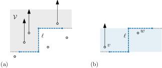
Each vertical (horizontal) line in not crossing a vertex, can be matched to a - (-)monotone wire in .
Proof
(Sketch) Consider a vertical line in not intersecting any vertex. Line partitions the set of vertices and vertical edges in into two subsets and . Consider a horizontal line in and consider the maximal intervals formed along it by elements from the same set or (see Fig. 6). Set and form exactly two maximal intervals along . Thus a -monotone line exists correctly splitting and . We can show that this -monotone line must intersect horizontal edges in the correct order as well.
Lemma 8
Drawing has spirality one relative to .
4.3 Single linear morph
We now show that any two planar orthogonal drawings and , where has spirality one relative to , can be morphed into each other using a single linear morph while maintaining planarity. Two drawings are shape-equivalent if for each edge the sequence of left and right turns is identical and the orientation of the initial segment is identical in both drawings. We say two drawings are degenerate shape-equivalent if edges may contain zero-length segments but an assignment of orientations to the segments exists that is consistent with both drawings. Two (degenerate) shape-equivalent drawings are per definition also unified. We can make degenerate shape-equivalent to by adding zero-length edges whenever maximum absolute spirality links in cross an edge. We say two points and on the drawing are split by a wire when and lie on different sides of the wire.
Lemma 9
Let and be two degenerate shape-equivalent drawings, where has spirality one. There exists a single linear morph from to that maintains planarity and orthogonality.
Proof
(Sketch) The partition of the drawing by all wires defines cells: regions of the plane not split by any wire. For each cell containing at least one bend or vertex, we can linearly interpolate all vertices and bends in to the unique vertex or bend location in . This directly defines a linear morph between and . To argue planarity of this morph, we assume for contradiction that there exist two points and on an edge or vertex of the drawing that coincide during the morph (excluding and ). Then and must be - and -inverted in compared to and there must be two vertices and that are - and -inverted and split by at least a tb-wire and a lr-wire. As the lr-wire and the tb-wire are monotone they cross at least three times (see Fig. 7). Contradiction.
Theorem 4.1
Let and be two unified planar orthogonal drawings of a (disconnected) graph , where has spirality . We can morph into using exactly linear morphs while maintaining planarity and orthogonality.
5 Linear complexity of intermediate drawings
Van Goethem and Verbeek [11] describe rerouting and a simplification operations that reduce the complexity of intermediate drawings to . These operations are not compatible with the batched linear morphs we described in Section 4. Below we show how to adapt these operations to the batched setting. These adaptations come at the cost of a single additional linear morph.
5.1 Rerouting
To avoid that the linear morphs introduce too many bends in a single iteration of the morph, we show how to route the wires such that only complexity is added to the drawing in each iteration. The initial rerouting of the wires in increases the maximum spirality by one, but it prevents any increase of spirality during the morph. Thus, using Theorem 4.1, morphs are sufficient to morph two equivalent drawings into each other while maintaining planarity and keeping complexity of the intermediate drawings to .
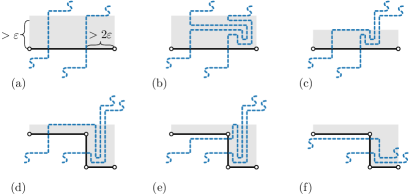
We reroute the wires in and as follows. Consider an edge that is crossed by at least two wires in . By Lemma 9 from [11] all crossing links have the same spirality. Assume w.l.o.g. that this spirality is positive, otherwise mirror the rotations and replace right by left. Let be a small distance such that the -band above is empty except for the links crossing and that there is more than a distance between the right-most crossing link and the right-endpoint of (see Fig. 8(a)).
We insert an -windmill of all crossing wires within the -band above by rerouting the wires as follows. First disconnect all crossing links within the -band above . Then reroute all wires in a parallel bundle to the right, beyond the right-most wire crossing . Now we spiral the bundle using right turns until the spirality of the links reaches zero. Next we unwind the bundle again within the spiral. Finally we reconnect the wires by routing back parallel to to maintain the original crossing points (see Fig. 8(b)). This rerouting can be executed without introducing crossings between the wires. It does increase the spirality of the drawing by one.
We now change each iteration as follows. Consider a horizontal edge crossed by links of maximum absolute spirality (assuming ) at the start of the iteration. Instead of performing a linear slide on all crossing links, we perform a single linear slide only on the rightmost crossing link. This slide creates a new vertical segment (see Fig. 8(c)). Thanks to the introduction of the -windmill, we can easily reroute the other crossing wires to intersect the new vertical segment instead of the horizontal segment without introducing other crossings (see Fig. 8(d)). The newly created crossing links must have spirality as all links crossing the same segment have the same spirality (Lemma 9 from [11]). We can reduce all remaining spirality links without introducing additional complexity in the drawing.
Lemma 10
At the start of iteration of the morph, all wires crossing an edge with links of spirality form an -windmill in an empty -band next to .
Lemma 11
Let be the first drawing of an iteration and the rerouted last drawing. The spirality of relative to is one.
Proof
Drawing compared to contains two additional bends in each edge crossed by maximum absolute spirality links in . We can make and degenerate shape-equivalent by inserting an additional zero-length segment at the right-most (left-most for negative spirality) crossing link for each edge crossed by maximum absolute spirality links. By Lemmata 9 and 11 we can morph the resulting into in a single linear morph while maintaining planarity.
As, independently of how many wires are crossing it, each edge only introduces two new bends, complexity increases by during each iteration. Thus the overall complexity is . We conclude that we can morph two drawings and , where has spirality , into each other using linear morphs while maintaining planarity and complexity of the drawing.
5.2 Simplification
By using rerouting we can ensure that the complexity of the drawing increases by at most in every iteration, but its complexity may still grow to over iterations. In this section we show how to simplify the intermediate drawings to ensure that the complexity after each iteration is .
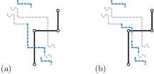
We again consider a single iteration starting with and ending with . Using rerouting we can find an alternative final drawing that also maintains planarity. We now introduce a redraw step that further simplifies into a straight-line drawing such that a linear morph from to still maintains planarity. The redraw step works as follows.
For each vertex in , consider a -sized square box surrounding that contains only and a -part of each outgoing edge from . If an incident edge is crossed by a maximum absolute spirality link in , then we reroute inside the -box around . Specifically, for an edge leaving rightwards, we reroute within the -box using the coordinates () (see Fig. 9(a)). Analogous rerouting can be done for edges leaving in other directions. For an edge crossed by a negative spirality link invert the left and right turns.
Lemma 12
We can redraw all edges in that were crossed by a maximum-spirality link in within -boxes while maintaining planarity of the drawing.
Proof
(Sketch) We can establish a relation between the spiralities of two segments incident at the same vertex. Using this relation we can argue that, after redrawing, no two edges leave a vertex in the same direction. As a result, there are no planarity violations within the -boxes around vertices.
Lemma 13
If is a straight-line drawing with spirality then there exists a straight-line drawing with spirality .
Proof
(Sketch) Let be the drawing obtained by applying rerouting to the last drawing of iteration . Consider an edge crossed by maximum absolute spirality links in . Edge has three segments in due to the two introduced bends. The first and last segment do not cross any wires. We can apply the redraw step to , resulting in three more segments at the start and end of . Finally we eliminate all additional segments of by performing zigzag-eliminating slides on these segments (see Fig. 9(b)).
Lemma 14
The spirality of relative to is one.
Proof
(Sketch) Let the main wire set be the set of wires used to compute the morph including rerouting from to . Consider a reference wire grid that is a straight-line wire grid in . Using Lemmata 7, 8, and 11 but swapping the roles of and , we obtain the result that there is an equivalent monotone set of wires in matching the reference grid in . Thus the spirality of relative to is one.
When straightening to only zigzag-removing slides are performed on segments not crossed by a wire from the main wire set. As such a segment was not crossed by a wire from the main wire set, the orientation of the segment is unchanged in . Specifically, any link of a wire from the reference wire grid that crosses such a segment must have spirality zero. When straightening to the zigzag-removing slides may insert additional bends in these reference wires, but the wires will remain monotone.
We can make degenerate shape-equivalent to as follows. For each edge crossed by maximum absolute spirality links, we split at the crossing with the right-most (or left-most if the links have negative spirality) crossing link and insert a zero-length segment. Furthermore, we add three zero-length segments at the endpoint of each such edge coincident with the respective endpoint.
Theorem 5.1
Let and be two equivalent drawings of a (disconnected) graph , where has spirality . We can morph into using linear morphs while maintaining planarity, orthogonality, and linear complexity of the drawing during the morph.
Acknowledgements. Bettina Speckmann and Kevin Verbeek are supported by the Netherlands Organisation for Scientific Research (NWO) under project no. 639.023.208 (B.S.) and no. 639.021.541 (K.V.). We want to thank the anonymous reviewers for their extensive feedback.
References
- [1] Soroush Alamdari, Patrizio Angelini, Fidel Barrera-Cruz, Timothy Chan, Giordano Da Lozzo, Giuseppe Di Battista, Fabrizio Frati, Penny Haxell, Anna Lubiw, Maurizio Patrignani, Vincenzo Roselli, Sahil Singla, and Bryan Wilkinson. How to morph planar graph drawings. SIAM Journal on Computing, 46(2):824–852, 2017.
- [2] Greg Aloupis, Luis Barba, Paz Carmi, Vida Dujmović, Fabrizio Frati, and Pat Morin. Compatible connectivity augmentation of planar disconnected graphs. Discrete & Computational Geometry, 54(2):459–480, 2015.
- [3] Patrizio Angelini, Fabrizio Frati, Maurizio Patrignani, and Vincenzo Roselli. Morphing planar graph drawings efficiently. In Proc. 21st International Symposium on Graph Drawing, pages 49–60, 2013.
- [4] Therese Biedl, Anna Lubiw, Mark Petrick, and Michael Spriggs. Morphing orthogonal planar graph drawings. ACM Transactions on Algorithms, 9(4):29:1–29:24, 2013.
- [5] Therese Biedl, Anna Lubiw, and Michael Spriggs. Morphing planar graphs while preserving edge directions. In Proc. 13th International Symposium on Graph Drawing, pages 13–24, 2006.
- [6] Thomas Bläsius, Sebastian Lehmann, and Ignaz Rutter. Orthogonal graph drawing with inflexible edges. Computational Geometry, 55:26–40, 2016.
- [7] Stewart Cairns. Deformations of plane rectilinear complexes. The American Mathematical Monthly, 51(5):247–252, 1944.
- [8] Giuseppe Di Battista, Giuseppe Liotta, and Francesco Vargiu. Spirality and optimal orthogonal drawings. SIAM Journal on Computing, 27(6):1764–1811, 1998.
- [9] Walter Didimo, Francesco Giordano, and Giuseppe Liotta. Upward spirality and upward planarity testing. SIAM Journal on Discrete Mathematics, 23(4):1842–1899, 2009.
- [10] Carsten Thomassen. Deformations of plane graphs. Journal of Combinatorial Theory, Series B, 34(3):244–257, 1983.
- [11] Arthur van Goethem and Kevin Verbeek. Optimal morphs of planar orthogonal drawings. In Proceedings of the 34th International Symposium on Computational Geometry (SoCG 2018), pages 42:1–42:14, 2018.
Appendix 0.A Omitted proofs
Theorem 4.1. Let and be two unified planar orthogonal drawings of a (disconnected) graph , where has spirality . We can morph into using exactly linear morphs while maintaining planarity and orthogonality.
Proof
By Lemma 8 for every iteration the initial drawing has spirality one relative to the first drawing of the next iteration. We can make and degenerate shape-equivalent by adding a zero-length edge at the crossing of each edge with each maximum absolute spirality link in . By Lemma 9 we can reduce the spirality of the drawing by one with a single linear morph.
Theorem 5.1. Let and be two equivalent drawings of a (disconnected) graph , where has spirality . We can morph into using linear morphs while maintaining planarity, orthogonality, and linear-complexity of the drawing during the morph.
Proof
Use induction to prove there exists a straight-line drawing of spirality such that there exists a planar morph from to that is comprised of linear morphs.
For the base case take a set of wires in with spirality . Reroute the wires to insert windmills next to all crossed edges, thereby increasing spirality to . By assumption the input was a straight-line drawing and trivially so no linear morph is required.
For the step let and let have spirality . By hypothesis is a straight-line drawing and a morph comprised of linear morphs exists starting at and ending at . Compute a morph from to as in [11]. Moreover, apply the rerouting as discussed in Section 4 to avoid introducing excess complexity. Let be the first drawing with spirality in this computed morph. Redraw by inserting additional intersection-free segments and then straighten the resulting drawing to a straight-line drawing as described. Also morph the set of wires from along in this process.
By Lemma 14 drawing has spirality one relative to . Make and degenerate shape-equivalent by inserting additional vertices in as discussed in Section 5.2. By Lemma 9 we can linearly morph into without violating planarity. Specifically we can perform this morph in reverse to obtain a morph from to .
Drawing has spirality , is straight-line, and concatenating the morph from to with the single linear morph from to results in a morph comprised of linear morphs.
We can remove any coincident or virtual bends from to maintain complexity.
Lemma 1. For each right-oriented link of a wire with positive (negative) spirality there exists a vertical line and a subsequence of links of crossing , such that the absolute spiralities of the links in sequence are , and when ordered top-to-bottom (bottom-to-top) along form the sequence .
Proof
Let be partial wire consisting of links of . Consider a vertical line through . We find the desired subsequence of by constructing it starting at the back. Assume for induction that the subsequence with links has been constructed. In the base case this is simply .
Link has spirality . Make a distinction on the orientation of . Assume is left-oriented, a similar argument holds when is right-oriented. As is left-oriented, . By the hypothesis occurs before (with spirality ) when ordered top-to-bottom along . Moreover as has the smallest spirality from all selected links in so far, must be the highest link in that crosses .
Let be the link from crossing directly below . We show crosses lower than any link from . If is the second link selected this is vacuously true, otherwise let be the link found in the step before . By the same argumentation link , with spirality , is the lowest link from crossing . As , and thus link . As was the link from crossing directly above , must cross below (see Fig. 10(a)).
Link is the first link from crossing below , thus (and therefore ) cannot cross through between and . Consequently, the sub-wire from to cannot enclose the origin of . This implies there is unique topological way to connect to and must have spirality or , which is uniquely defined by the orientation of (see Fig. 10(b)). If the spirality of is then we add to , otherwise we repeat the downwards search. As spirality decreases in steps of two and the lowest link crossing has spirality at most (from Lemma 3 in [11]) a suitable link with spirality will be found.
Lemma 2. An equivalent set of lr-wires with spirality exists.
Proof
We prove the statement constructively by induction on the size of the constructed set. Assume an equivalent set of lr-wires with spirality exists, where each wire is shortest with respect to the previously inserted wires. In the base case .
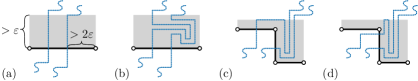
For the step consider a wire that does not have a matching counterpart in . Find the shortest lr-wire in that matches such that is an equivalent set of size . Consider the right-oriented link with maximum absolute spirality . By Lemma 1 there exist a (topological) spiral around that has layers. We bound the number of layers surrounding to . Thus, it must also be that and the spirality of is . To achieve this we classify the layers of the spiral by their containment of the drawing, a layer (1) contains a vertex, or (2) is crossed by an edge, or (3) contains no part of the drawing (but may contain wires).
Clearly there are at most layers that contain a vertex of the drawing. If a layer contains no vertex, but does contain an edge then that edge must cross through the layer. As each edge is crossed at most once by , such an edge must cross exactly once. Each edge can only be involved in the layers left and right of the crossing with in this way. Thus only layers contain an edge but no vertex. The remaining layers contain subsections of wires or are empty. Trivially an empty layer cannot exists, as otherwise is not shortest.
We show that no layer exists that contains only wires (including parts of itself). The boundary of a layer is formed by and two straight-line segments along . We refer to two parts of the boundary along as the gates of the layer.
Assume for contradiction there is a layer that only contains subsections of wires (possibly itself). Lr-wires do not cross and hence must enter and leave through the gates. As contains no part of the drawing and the lr-wires are each shortest with respect to the previously inserted wires they cannot consecutively enter and leaves through the same gate. Moreover, the order of the wires at both gates is identical.
Disconnect all lr-wires at the gates of . Also disconnect at the lower link adjacent to each gate. Remove all disconnected components. Reconnect the remaining parts locally along to ensure the remaining links of all wires are visited in the same order and no crossings occur (see Fig. 4(d)). All wires crossing have been shortened by this. Contradiction, as all wires in the existing equivalent set as well as itself, were shortest with respect to the previously inserted wires.
We conclude that there can be at most layers. Therefore, the maximum spirality of any link and thus the newly introduced lr-wire is .
Lemma 3. An equivalent set of wires with spirality exists.
Proof
By Lemma 2 we can insert all lr-wires with spirality . By Lemma 2 from [11] the spirality of intersecting links is the same. Thus when a tb-wire intersects a lr-wire it has spirality and we can consider the regions between these intersections individually. Between two intersections no pair of tb-wires intersect. Furthermore, there are no crossings with the pair of lr-wires at the border of the region. We can consider the same proof as Lemma 2 where a wire may now either be a lr-wire or a tb-wire. Thus, in the region between two lr-wires the spirality of each tb-wire increases (decreases) by at most and is again when crossing the second lr-wire. It follows that the overall spirality of the tb-wires is also .
Lemma 4. Two vertices and can be inverted by a zigzag-removing slide along link , if and only if and are separated by .
Proof
W.l.o.g. assume is vertical and the spirality is positive (see Fig. 11). Let be the set of vertices moved by a zigzag-removing slide on . If or then are moved equally in the same direction and cannot be inverted. Hence either or ; assume . All vertices in move up by the length of . To be inverted we need that initially , but also that . But then and must both be in the strip spanned by and they must be separated by .
Let , where are the first and last drawing of an iteration. Specifically is the first drawing with spirality and is the first drawing with spirality .
Lemma 5. Two vertices and that are -inverted (-inverted) first during a morph from to , are separated by a horizontal (vertical) staircase of maximum spirality links in .
Proof
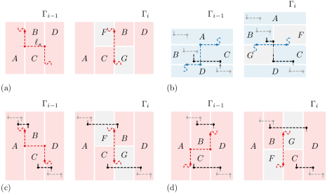
Assume w.l.o.g. that only one inversion occurs and it occurs from to , otherwise consider the initial part of the morph. Assume that , in all drawings from to and , in . We prove the claim for the intermediate drawings in backwards direction starting from . By Lemma 4 and are separated by a single maximum absolute spirality link in . This trivially satisfies all constraints for a downwards staircase. As and in and in , link has positive spirality.
Assume the sequence composes a downwards staircase in , where . For convenience of argument we consider and as zero-length horizontal links that are part of . We show a downwards staircase separating and also exists in . Let link be the link causing the linear slide from to . Define four rectangular regions surrounding that partition the plane in (see Fig. 12(a)). During the linear slide from to all four regions are maintained intact. Moreover, two new regions are present in . However, as regions are maintained intact and together contain all vertices, regions do not contain any vertices.
Assume is not also a downwards staircase in otherwise we are done. To break any of the staircase properties the - (-)order of two endpoints of links in must change between and This can only occur if the respective endpoints are separated by (Lemma 4) and hence at least one link from must be overlap with region and one link must overlap with region . Let be the sub-staircase consisting of the links of upto the last link that intersects, or is contained in, region . Staircase consists of the remaining links and, specifically, the first link of must intersect or be contained in region . As the endpoints of the links in are monotone decreasing in , region contains no links from , and region contains no links from . Hence, as no pair of vertices in a sub-staircase is separated by , all staircase properties are maintained for and separately between and . Let be the last link from and the first link from . Make a case distinction on the orientation of .
Assume is vertical (see Fig. 12(b)). A vertical slide can falsify only the -monotonicity of . As the -projection of and touches (overlaps) in and regions contain no vertices ends at the right border of and starts at the left border of . Any vertical linear slide (degenerately) maintains the -order on each vertical line. Thus also in the right endpoint of is above (or equal with) the left endpoint of . In the boundary case and form a single link in . In each case forms of a valid staircase in .
Assume is horizontal. A horizontal slide can falsify the -monotonicity or the overlap of links. Consider the spirality of .
First, assume has positive spirality (Fig 12(c)). As is a valid staircase in the projection on the -axis of any two non-adjacent links is non-overlapping. Then and cannot be fully contained in respectively as otherwise either is contained in in or vice versa, and therefore at least one pair of non-adjacent links must overlap. Moreover, from only enters and only enters . In only the right endpoint of and the left endpoint of may be inverted. If not, then is a downwards staircase in as well. If so, then by Lemma 4 and are separated by . Thus forms a downwards staircase in .
Second, assume has negative spirality (Fig 12(d)). Then in the projection on the -axis of non-adjacent links from may overlap. As in both and at least some pair of links from and overlap. Select a subsequence from satisfying all constraints by dropping links from the end of until only one link from overlaps a link from . Then drop links from the start of until no non-adjacent pair of links in overlap.
Note 1
If two vertices are inverted along both axes during a morph from some drawing to some drawing , then there exists a submorph where and are inverted exactly once along both axes.
Lemma 6. Two vertices and can be inverted along only one axis during the morph from to .
Proof
Assume for contradiction a pair of vertices exists that is inverted along both axes. Assume they are inverted along both axis exactly once, otherwise consider the submorph where this is the case. W.l.o.g. let , in , , in all drawings from to , and , in .
By Lemma 5, and the relative position of and , there exists a downwards staircase separating and in . By Lemma 4 and the inversion of from to there must be a vertical link with positive spirality separating in . We consider the regions surrounding the link in that causes the linear slide from to and the matching regions in . As regions and cannot contain any vertices, the staircase separating must have a link ending at the right boundary of and a link ending at the left boundary (see Fig. 12(b)). Specifically, the -coordinate of is greater or equal than the -coordinate of in . As any vertical slide, in particular the one from to , maintains the order on a vertical line we must also have in . Contradiction.
Lemma 7. Each vertical (horizontal) line in not crossing a vertex, can be matched to a - (-)monotone wire in .
Proof
Let be a vertical line in not intersecting any vertex. Line partitions the set of vertices and vertical edges in into two subsets . We consider the shape of these sets in . Let be a horizontal line in and consider the elements from and that intersect . Order the elements left-to-right along and form maximal subsets of consecutive elements from the same set (see Fig. 13(a)). If vertices from coincide in , then we order those vertices such that vertices from come before vertices from . To differentiate we refer to the maximal subsets formed as intervals.
Assume for contradiction there are two consecutive intervals and when ordered left-to-right along . Let and . We have in and in . As and are -inverted, they (or their endpoints) cannot be -inverted between and (Lemma 6). Assume are vertical edges in and an endpoint of is in the horizontal strip defined by (see Fig. 13(b)). The case where or are vertices is analogous. As the morph is planar cannot move through while morphing to . But then changed in the -order with at least one of the endpoints of during the morph. Contradiction.
We conclude no interval composed of elements from can come after an interval composed of elements from . Thus there at most two maximal intervals on each horizontal line in and they are ordered with the elements from occurring first. It follows that a -monotone wire must exist in that correctly partitions the vertices and vertical edges.
A -monotone line intersects each horizontal edge at most once and, as it partitions the vertices correctly, it must intersect exactly the required horizontal edges. It is left to prove that such a -monotone wire also intersects the horizontal edges in the correct order. Consider an arbitrary pair of horizontal edges that is intersected by in this order in . If have the same vertical order in then the claim trivially holds. Assume the end-points of are -inverted in (see Fig. 13(c)). Then by Lemma 6 the -order of the end-points is the same in and . W.l.o.g. of assume an endpoint of is in the horizontal strip defined by in and . Vertex must have changed in the -order with at least one of the endpoints of during the morph. Contradiction.
Lemma 8. Drawing has spirality one relative to .
Proof
To determine the spirality of relative to we need to show a monotone wire-grid exists in that is equivalent to a straight-line wire grid in . To this end, consider a new straight-line wire-grid in . By Lemma 7 we can find an equivalent - (-) monotone wire in for each straight wire in . All that is left to show is that there is also set of monotone wires in that together form an equivalent set to the wires in .
Assume for contradiction such a set does not exist. Then for any set of monotone wires in , each individually equivalent to a straight wire in , at least one pair of tb- (lr-) wires intersect at least twice or one pair of a tb-wire and a lr-wire intersect at least three times.
Assume a pair of adjacent -monotone tb-wires intersect at least twice (see Fig. 14(a)). Consider the top-most two intersections. The region enclosed by the wires cannot contain vertices as both wires partition the vertices equivalently to . As the enclosed region is simple and every edge is intersected at most once by a single wire, the order in which edges are intersected along the different wires is the same. We can locally reroute both wires along the enclosed region to remove both intersections. Repeated application removes all intersections. Contradiction.
Assume an -monotone lr-wire and a -monotone tb-wire intersect at least three times. Consider a region enclosed between two consecutive intersections . Assume w.l.o.g. that intersects left to right in (see Fig. 14(b)). If does not contain vertices, then consider the left-most, lowest -monotone increasing path through . As the boundary right of is -monotone decreasing, must also be -monotone decreasing. Reroute both wires along between and to remove intersection and .
Any region enclosed between two remaining intersections must contain at least one vertex. Consider the leftmost three consecutive intersections along . We have . Assume for contradiction crosses through first (last) out of these three intersections. Then upto , upto , and the boundingbox around the drawing enclose a simple region. Wire enters this region through , but cannot exit it without intersecting somewhere before . Contradiction, as are the first three intersection along . Thus either or .
Assume w.l.o.g. (see Fig. 14(c)). The wires between these intersections enclose two disjoint regions . Each region contains at least one vertex, let and . Subdivide the plane into four axis-aligned quadrants at . Region lies in the top-left quadrant and in the bottom-right quadrant. Thus, and in . As the wires are equivalent to , by construction and in . However, by Lemma 6 vertices cannot be both inverted along both axes. Contradiction.
We conclude that an equivalent set of - respectively -monotone wires exists in matching the straight-line wiregrid in . By definition has spirality one relative to (with respect to the described set of wires).
Lemma 9. Let and be two degenerate shape-equivalent drawings, where has spirality one. There exists a single linear morph from to that maintains planarity and orthogonality.
Proof
We consider the following linear morph between and and prove it has the desired properties. The partition of the drawing by all wires defines cells; regions of the plane not split by any wire. For each cell containing at least one bend or vertex, linearly interpolate all vertices and bends in to the unique vertex or bend location in . This directly defines a linear interpolation for each point (not necessarily a vertex or bend) between and .
First, we prove that during the described linear morph the drawing remains orthogonal. The endpoints of all (zero-length) segments crossing a tb-wire have the same - coordinates in and , hence they remain horizontal. Symmetrically all segments crossing a lr-wire remain vertical. All other segments morph to a single point and remain horizontal or vertical as well.
Second, we prove that during the described linear morph the drawing remains planar. Assume for contradiction there exist two distinct points on an edge or vertex of the drawing that coincide during the linear interpolation (excluding ). By linear motion the -coordinates and -coordinates of and change linearly. To be identical at a time during the morph and must be both - and -inverted in compared to . Note that this is not excluded as we do not base our analysis on linear slides.
Assume that and in . The case where either the - or -coordinates are identical in and works similarly. Distinguish whether and are on a horizontal or vertical segment. We will work out the first case and indicate the setup for the other cases, which are analogous.
First, assume and are both on a vertical segment in (see Fig. 7(a)). Let be the top endpoint of the segment containing and the bottom endpoint of the segment containing . In we have and . As and have distinct - and -coordinates they are split by at least one tb-wire and one lr-wire in .
The matching (monotone) wires in split and identically. Furthermore, vertical segments and also exist in , though they may have zero-length as they were introduced at a wire-intersection. Thus and in . In vertices are split by a -monotone tb-wire. Therefore, it must also be that in . Similarly, as and are split by an -monotone lr-wire, . However, then the lr-wire and tb-wire must cross at least three times. Contradiction.
Second, assume is on a horizontal segment and on a vertical segment (see Fig. 7(b)). Let be the right endpoint of the segment containing and be the bottom endpoint of the segment containing . Third, assume and are both on a horizontal segment (see Fig. 7(c)). Let be the right endpoint of the segment containing and be the left-endpoint of the segment containing .
We conclude there do not exist two distinct points on the edges (vertices) of the drawing that coincide during the linear morph.
Lemma 10. At the start of iteration of the morph, all wires crossing an edge with links of spirality form an -windmill in an empty -band next to .
Proof
At the start of the morph . As no edge is crossed by links of spirality the statement holds vacuously.
For the maintenance assume the statement holds at the start of iteration . We prove the statement for . Assume w.l.o.g. that some edge is crossed by links with positive spirality . By hypothesis there is a -windmill next to inside an otherwise empty -band (see Fig. 15(c)). As a corollary of Lemma 4, any slides along links of the wires outside of the -band do not affect the -windmill next to . Thus we only concern ourselves with the local structure.
We reduce the right-most link crossing and reroute the remaining crossing wires (see Fig. 15(d)). This maintains all links in the windmill except for the first link of the right-most wire. Performing linear slides on the remaining spirality links within the -band also removes the first link in the windmill for the other wires. Reducing all other spirality links also removes the last link in the spiral for all wires. This leaves a -windmill inside an otherwise empty -band next to (see Fig. 15(f)).
Lemma 11. Let be the first drawing of an iteration and the rerouted last drawing. The spirality of relative to is one.
Proof
We show that rerouting wires does not destroy staircases. When rerouting the link crossing and the first link after the crossing are replaced by four links that together span the same width and the same height. W.l.o.g. consider the horizontal link and its replacement links. W.l.o.g. assume the link has positive spirality and that it was part of a downwards staircase (see Fig. 16(a)). The two links replacing it span the same width and have the same spirality. Replacing the original link in the staircase by the two new introduced links maintains the property of the staircase that the left endpoints are -monotone increasing and -monotone decreasing. Clearly the projection of the two introduced links touches. Furthermore, as they jointly span the same width they must overlap with the previous and next links in the staircase. (see Fig. 16(b)). If the projection of non-consecutive links in the staircase overlap, then a subset of the links exists where all staircase properties are satisfied.
The following technical lemma is based on Lemma 12 in [11].
Lemma 15
Let be a vertex with at least two outgoing edges and let be the turn made at going from to , where for a right turn, for a left turn, and otherwise. Let be a link crossing and be a link crossing . We have .
Proof
Edge and either are both horizontal (vertical) in or not.
For the case where the edges have different orientations, w.l.o.g. assume is a left-outgoing edge for and a top-outgoing edge for in . By construction and are intersected by a pair of wires and , and they cross before crossing respectively . Wires and together with edges and must then enclose a simple region in . As the wires in form an equivalent set this simple region also exists , however, the shape may be different, moreover, the orientation of the outgoing edges at may be different.
This cycle by construction contains at least three left turns. Two at the crossing of the wires with and , and one at the crossing of the wires. The turn at depends on the configuration of and in . Let be the links of crossing and . Furthermore, let be the spirality of the links of and at the crossing between and . As the number of left turns is four larger than the number of right turns when traversing a cycle counter-clockwise we have , simplified . When, in , is clockwise adjacent to at then we get .
For the case where both edges are horizontal (vertical) a similar argument holds, but now the cycle is formed by two wires from and one wire from resulting in one more left turn. We obtain .
Combining all bounds gives the result.
Lemma 12. We can redraw all edges in that were crossed by a maximum-spirality link in within -boxes while maintaining planarity of the drawing.
Proof
Trivially planarity violations occur only inside the -boxes. Let be the redrawn version of . There are two possible cases causing a planarity violation in . First, two perpendicular edges leaving coincide internally after the redraw step. This occurs if one of the edges is crossed by links of absolute spirality and the other is not. Second, two edges leaving in opposing direction coincide internally after the redraw step. This occurs if one of the edges is crossed by links of spirality and the other by links of spirality .
For the first case, w.l.o.g. assume is an right-outgoing edge of and a bottom-outgoing edge. Let be a link crossing and a link crossing in . Assume w.l.o.g. and . By Lemma 15, using , in we have . Specifically, as and no larger spiralities exists in , we must have . Contradiction.
For the second case, w.l.o.g. assume is a right-outgoing edge of and a left-outgoing edge. Let be a link crossing and a link crossing , where and . Using Lemma 15, with , we get . Contradiction.
Lemma 13. If is a straight-line drawing with spirality then there exists a straight-line drawing with spirality .
Proof
There exists a morph from to monotonously decreasing spirality while using rerouting to prevent excess complexity in the edges. Let be the first drawing with spirality in this morph. Consider an edge that is crossed by maximum absolute spirality links with positive spirality in . Mirror right and left turns for edges crossed by maximum absolute spirality links with negative spirality. Edge has three segments in that are joined by a right turn followed by a left turn.
Redraw within the -boxes near the endpoints to create two left turns and a right turn at the start of the edge, and one left turn and two right turns at the end of the edge (see Fig. 9(b)). Thus the bends in in can be encoded as , where encodes a left turn and a right turn. Split differently we have where any wire crossing the edge crosses in the segment between the two groups of bends.
We can remove a pair of consecutive bends by performing a zigzag-removing slide on the segment between the bends. As any such segment is not crossed by wires this does not introduce new bends in the wires. The result is a straight-line version of . As no new bends were introduced in any of the wires, the spirality is still .
Lemma 14. The spirality of relative to is one.
Proof
Let the main wire set be the set of wires used to compute the morph including rerouting from to . Consider a reference wire grid that is a straight-line wire grid in . We use the reference wire grid to prove the spirality of relative to is one. Using Lemma 7, 8, 11 but swapping the roles of and , we obtain the result that there is an equivalent monotone set of wires in matching the reference grid in . (We remark that the argument for Lemma 8 is slightly easier in this direction as no coincident vertices exist in .) Let a segment in that does not cross a wire of the main wire set be a free segment. Free segments have the same orientation in as in .
We consider straightening while deforming the set of reference wires along. The resulting deformed set of wires for is equivalent to the straight-line reference grid in . What is left to prove is that these wires are still - (-)monotone and hence the spirality of relative to is one.
If a horizontal (vertical) free segment is crossed by a reference wire in , then it must be crossed by a tb- (lr-)wire as the orientation of the segment is the same in and the reference grid consists of straight lines in . Straightening the segment using a zigzag-removing slide introduces two bends and a new horizontal link in the tb-wire. Introducing a horizontal link cannot break -monotonicity of the wire though. Thus deforming the drawing and the reference grid while simplifying maintains the spirality of the reference grid. But then there exists an equivalent set of monotone wires in matching the straight-line wires in . We conclude that the spirality of is one relative to .