Operation of ILC250 at the Z-pole
Kaoru Yokoya, Kiyoshi Kubo, and Toshiyuki Okugi,
High Energy Accelerator Research Organization (KEK), Japan
Aug.27. 2019
ILC (International Linear Collider) is under consideration as the next global project of particle physics. Its Technical Design Report, published in 2013, describes the accelerator for the center-of-mass energies above 200GeV. The operation of ILC at lower center-of-mass energies has not been studies intensively. This report discusses the operation of the ILC at a center-of-mass 91.2GeV and presents a possible parameter set.
1 Introduction
When the serious design study of the ILC started in 2005, the first design criteria was “a continuous centre-of-mass energy range between 200 GeV and 500 GeV” (TDR[1], page 3). Hence, the TDR quoted the luminosities only for the center-of-mass energies at 200, 230, 250 GeV and above. Obviously, once ILC is built, lower energies such as Z-pole (91.2GeV) and W-pair threshold (160GeV) would be of interest, though these are not the main concern of ILC.
In the baseline design of ILC the positron production scheme using undulator magnets is adopted. In this sheme the electron beam, before going to the collision point, goes through undulators to produce photons (over several MeV) which create positrons on a target. To this end the electron energy must be at least about 125 GeV. For operation at GeV TDR adopted the so-called 5+5Hz scheme111The electron linac is operated at 10Hz: 5Hz to accelerate the beam to GeV which produces positrons and another 5Hz to accelerate the beam to for collision experiment. This is sometimes referred to as ‘10Hz’ operation. However, there is another 10Hz operation, in which all systems, the injectors, damping rings, main linacs etc., are operated at 10Hz to make 10Hz collisions. Thus, to distinguish from the latter we call the former ‘5+5Hz’.
The possibilities of ILC operation at the Z-pole (and W-pair threshould) was first discussed by N. Walker[2]. Later, K. Yokoya gave a short report at a workshop.[3]. These reports gave a possible luminosity range at the Z-pole by using a scaling law and pointed out many challenges to be studied later.
The luminosity is given by
| (1) |
where is the repetition rate of the beam pulse, the number of bunches in a pulse, the number of particles per bunch, and is the horizontal (vertical) beam size at the IP (interaction point). (luminosity enhancement factor) expresses the effects of the beam-beam force. With the optics around the IP fixed, is proportional to the square root of the geometric emittance . Since the geometric emittance is inversely proportional to the beam energy, a naive scaling expects . However, the large geometric emittance at low energies causes a larger beam size at the final quadrupole magnets such that the beam halo may produce backgrounds to the experiments. Such halo particles usually are eliminated by collimators in upstream. However, too deep a collimation would cause further backgrounds and enhancement of beam fluctuation by the wake field in the collimators. In such a case one has to relax the beta functions at the IP, which brings about a lower luminosity. If this happens in one of the and planes, then the luminosity would be proportional to , and if in both planes, to . The above report[2] gave a luminosity range , corresponding to or based on the luminosities at 200-250GeV in the TDR.
Proposed Parameters for Operation at Z-pole
The baseline parameters for 250GeV is listed for reference.
Center-of-Mass Energy
91.2
250
GeV
Beam Energy
45.6
125
GeV
Collision rate
3.7
5
Hz
Electron linac repetition rate
3.7+3.7
5
Hz
Pulse interval in electron main linac
135
200
ms
Electron energy for e+ production
125
125
GeV
Number of bunches
1312
1312
Bunch population
2
2
Bunch separation
554
554
ns
RMS bunch length
0.41
0.30
mm
Electron energy spread at IP (rms)
0.30
0.188
%
Positron energy spread at IP (rms)
0.30
0.150
%
Electron polarization
80
80
%
Positron polarization
30
30
%
Emittance from DR (x)
4
4
m
Emittance from DR (y)
20
20
nm
Emittance at the linac exit (x)
5
5
m
Emittance at the linac exit (y)
35
30
nm
Emittance at IP (x)
6.2
5
m
Emittance at IP (y)
48.5
35
nm
Beta x at IP
18
13
mm
Beta y at IP
0.39
0.41
mm
Beam size at IP (x)
1.12
0.515
m
Beam size at IP (y)
14.6
7.66
nm
Disruption Param (x)
0.41
0.51
Disruption Param (y)
31.8
34.5
Geometric luminosity
0.95
5.29
Luminosity
2.05
13.5
Luminosity enhancement factor
2.16
2.55
Luminosity at top 1%
99.0
74
%
Number of beamstrahlung
0.841
1.91
Beamstrahlung energy loss
0.157
2.62
%
Since the above studies there have been several changes in the ILC design. Most relevant ones for our context are:
-
•
The initial center-of-mass energy for the ILC was reduced from 500GeV to 250GeV in order to concentrate on the Higgs study.
-
•
The undulator length was extended from 147m to 231m so that the electron beam of 125GeV can produce sufficient number of positrons. Thus, we do not need 5+5Hz scheme for GeV.
-
•
The normalized horizontal emittance at the IP was reduced from 10m to 5m by modifying the damping ring design. This change improved the luminosity at GeV by a factor . [5]
In the present report, taking into account these changes we give study results on the possible luminosity at the Z-pole.
Table 1 shows the preliminary parameter set to be described in this report. The study results for each item will be discussed in the later sections.
2 Repetition Rate
As mentioned in the introduction, the TDR adopted the ‘5+5Hz’ scheme for the operation at low energies. This scheme demands more electric power than the normal 5Hz operation but this is possible because the power system of 500GeV machine is available. For example, the electron linac would produce 45.6GeV and 150GeV electron beams alternatingly. The sum of the power of these two is less than the power for 250GeV electron beam.
However, this is not true for the ILC 250GeV. The installed power is not sufficient for 5+5Hz operation. In this section we estimate the possible highest repetition rate under the limitation of the power system of ILC 250GeV.
First, let us discuss how to switch the beam energy. To get a 45.6GeV electron beam with a 125GeV linac, one might want to accelerate the beam to 45.6GeV with the full gradient and turn off the power for the rest of the linac. This is better from the view point of the beam dynamics in the powered cavities. However, for avoiding the effects of the beam-induced field in the un-powered part of the linac, one has to detune the cavities quickly (a few Hz). This can only be done by piezo tuners but the dynamic range of the equipped tuners is far from this requirement. Thus we have to accelerate the electron beam uniformly over 5km with a very low gradient (8.76MV/m compared with 31.5MV/m for 125GeV) 22231.5(45.6-15)/(125-15)=8.76 MV/m, since the injection energy to the main linac is 15GeV. Thus, the electron linac must be operated with gradients 31.5MV/m and 8.76MV/m, alternatingly.
The possible parameters of the RF system are shown in Table 2. (This estimation was done by T. Matsumoto.[4]). The parameters of the normal operation for GeV are identical to the one in the left column except the repetition is 5Hz. Since the gradient is low for the 45.6GeV beam, the klystron power is low and the fill time (and hence the RF pulse length) is short. One can find from this table that the integral of the modulator output in one cycle is 14.66MW1.65ms + 7.83MW1.06ms = 32.5kJ, which is larger than the first term (125GeV) by a factor 1.34. Therefore, the highest possible repetition rate is 5Hz/1.34 3.7Hz. There will be some margin in the actually installed power which can raise the rate a little, but we adopt 3.7+3.7Hz operation in the following.
| e+ production | collision | ||
| Final beam energy | 125 | 45.6 | GeV |
| Average accelerating gradient | 31.5 | 8.76 | MV/m |
| Peak power per cavity | 189 | 77.2 | kW |
| Klystron peak power | 9.82 | 4.15 | MW |
| Klystron efficiency | 67 | 53 | % |
| Modulator output | 14.66 | 7.83 | MW |
| Fill time | 0.927 | 0.328 | ms |
| Beam pulse length | 0.727 | 0.727 | ms |
| RF pulse length | 1.65 | 1.06 | ms |
| Repetition rate | 3.7 | 3.7 | Hz |
3 Damping Rings
Basically, the damping rings designed for the TDR are capable of 5+5Hz operation by a reinforcement of the wiggler magnets and the RF system. However, the design has been changed slightly since AWLC2017 at SLAC[5] (smaller horizontal emittance m to m). It must be checked whether the new design accepts 3.7+3.7Hz operation.
In 3.7+3.7Hz operation, the beam stay in the damping ring for 1/3.7Hz/2=135ms, while 200ms in the baseline 5Hz operation.
Figure.1 shows the transverse damping time as a function of the wiggler strength parameter. Factor 1 corresponds to the field 1.29T (curvature 0.07745m-1).
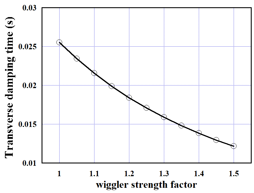
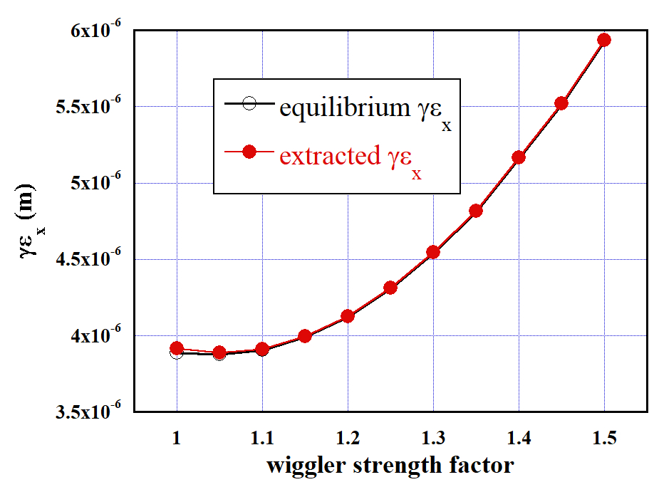
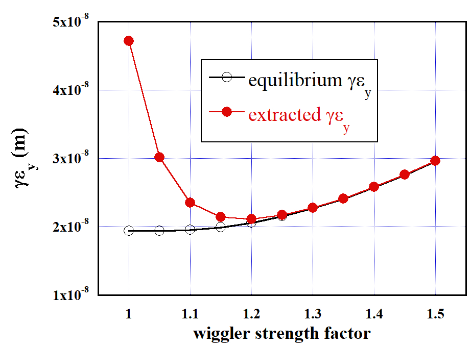
Figure.2 shows the equilibrium and extracted emittances from the damping ring as functions of the wiggler strength parameter. The initial emittance is radm (for positron). As the vertical-horizontal coupling, 0.005 is assumed.
The figure on the right shows that the extracted vertical beam emittance is too large if the wiggler strength factor 1.1 because the damping is not fast enough. The strength factor 1.15 (Tesla) gives m nm. The latter is slightly larger than the value in Table 1 (20nm) but a slight improvement of the coupling would be sufficient.
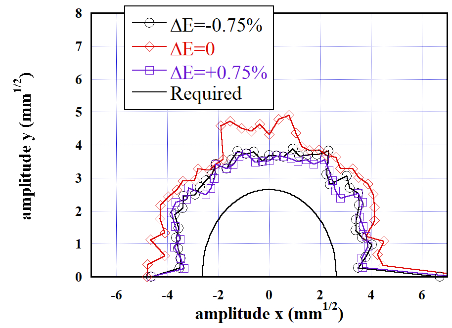
Because the wiggler strength is increased, the dynamic aperture of the damping rings must be re-examined. The requirements are, as in TDR:
-
•
Normalized betatron amplitude
-
•
Energy deviation %
The wiggler strength factor is set to 1.15 (curvature 0.0891 m-1). The acceptance criterion is the survival after 1000 turns.
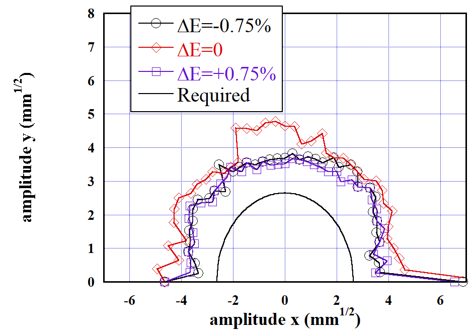
Figure.3 show the results. The plot on the left (right) shows the aperture without (with) the sextupole components of the wiggler field. (Adopted sextupole field is at mm as in TDR[1] page 115.) The half circle at the center-bottom shows the required aperture for the transverse emittance mentioned above. As is seen, the dynamic apeture is sufficient. The sextupole field has no significant effects. The magnet error has not been included here, but its effect was not significant in the previous calculation with the wiggler strength 1[3].
All simulations in this section were done using the computer code SAD[6].
4 Electron Main Linac
There are several issues to be studied on the 3.7+3.7Hz operation of the electron main linac.
-
(a)
The RF system must deliver different pulses (power and pulse length) alternatingly with an interval of 135ms.
-
(b)
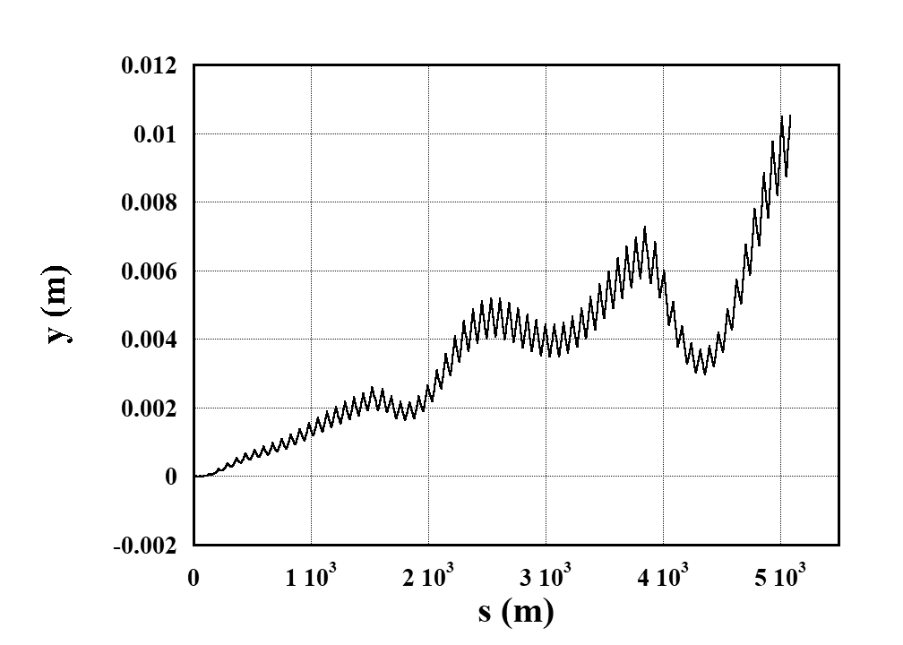
The orbits for the 45.6GeV (colliding) and 125GeV (positron production) beams are different even without alignment errors due to the earth’s curvature. This difference must be corrected before injection to the undulator section.
-
(c)
The emittance increase by the misalignment must be checked. In partucular the major concern is the colliding beam because the accelerating gradient is very low.
As mentioned in the Sec.2, the 45.6GeV (colliding) beam must be created by uniform acceleration over the entire linac rather than full gradient followed by detuned cavities. There seems to be no other RF-technical problem of (a) in the alternating operation.
A simulation was done for the issue (b). Figure.4 shows the orbit difference. It amounts to 1cm at the end of the linac. This difference (and the orbit angle difference, which is not shown here) must be corrected before entering the undulator section by using 3.7Hz pulsed magnets. A short section must be allocated (the required length still need to be estimated) but there is no problem as far as the field strength is concerned. It must be checked whether the field can be accurate enough. In this respect it is better to bend the positron production beam, though the energy is higher, because the colliding beam must be extremely stable in particular in the vertical plane.
In addition, the wakefield effects (mainly resistive wall) for the colliding beam in the undulator section should be studied in more detail because the beam energy is low. If the effect turns out to be serious, we have to prepare a beamline to bypass the undulator.
For the issue (c) simulations have been done under the following assumptions.
-
•
The vertically curved orbit as mentioned above.
-
•
Orbit correction was done for the colliding beam (45.6GeV). The same steering setting was used for the positron production beam since the emittance increase is not an issue for the latter.
-
•
The assumed misalignments (every cavity and quadrupole magnet are misaligned independently, ignoring the module structure.)
-
–
Quadrupole magnets offset 0.36mm
-
–
Cavity offset 0.67m, tilt 0.3mrad
-
–
BPM offset m
The numbers are r.m.s of Gaussian distribution cut at 3 sigmas.
-
–
-
•
Initial normalized emittance =20nm
-
•
DFS (Dispersion-free steering) with energy change 20%.
Two cases were simulated for the bunch length and the initial energy spread:
-
•
Bunch length 0.3mm, energy spread 1.2%
-
•
Bunch length 0.41mm, energy spread 0.9%
The reason of the second case is mentioned in the next section. In the case of longer bunches the expected emittance increase due to the wake field (combined with misalignment) is larger but that due to the energy spread is smaller.
Figure.5 shows the vertical emittance increase in the misaligned linac as a function of the final beam energy. What is shown is the average emittance increase of 100 different random number sets. 333Note: =125GeV in this table indicates the case where the orbit tuning is done for this energy. This is true for the baseline case =250GeV. However, the 125GeV beam for the positron production in 3.7+3.7Hz operation is different because the tuning is done for 45.6GeV beam. The emittance of the positron production beam will be significantly larger. Nontheless, this is not an issue because the positron production does not require a very low emittance beam.
The average emittance increase of the 45.6GeV beams with 0.41mm is 6.3nm, sufficiently smaller than the emittance budget 10nm. (Note that the emittance increase would amount to nm for Z-pole operation of ILC500[3] due to the even lower gradient in longer 10km linac.) The increase in the shorter bunch case is slightly smaller, which indicates the effect of the wake is slightly larger than that of the energy spread.
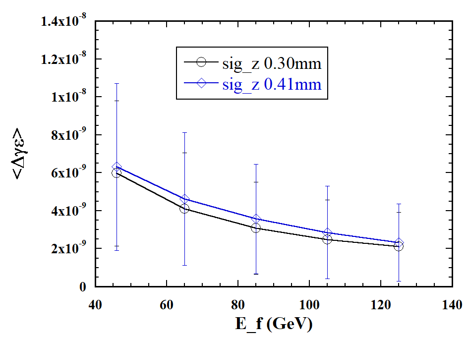
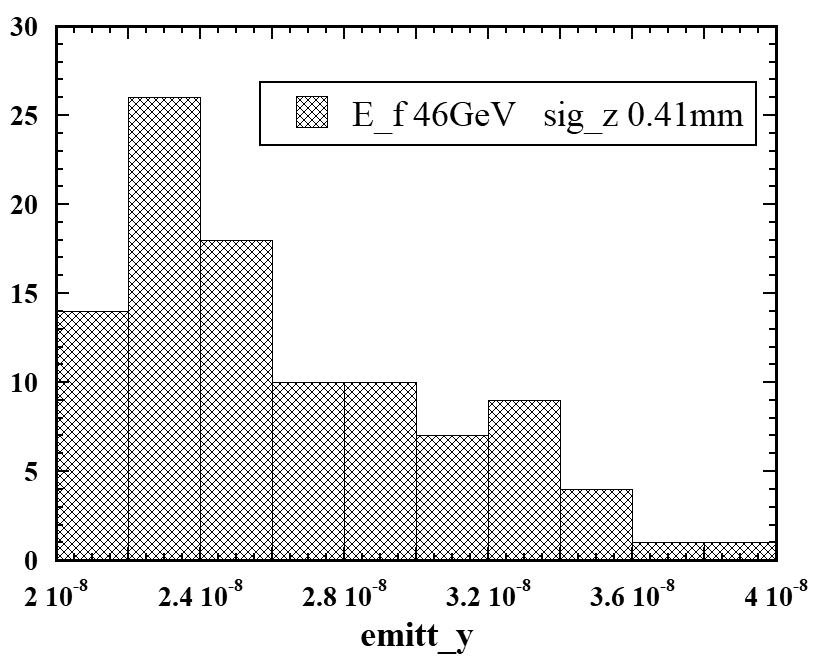
Figure.6 shows the distribution of the final emittance for the case of the final beam energy 45.6GeV and 0.41mm. The final emittance at the 90% confidence level is nm, which slightly exceeds the budget but still in an acceptable level.
5 Beam Delivery System (BDS)
There are three major issues in BDS related to the Z-pole operation.
-
•
Collimation depth as explained in the introduction
-
•
Momentum band width
-
•
Wake field effects
Collimation Depth
The geometric emittance is inversely proportional to the beam energy. It is a factor 125/45.6=2.74 times larger than at =250GeV. The synchrotron radiation from particles in the halo with large angles at the IP cause background to the experiment. These particles should be eliminated by collimators upstream. However, the required collimation in the horizontal plane is too deep () with the TDR parameters even at GeV (=250GeV). This was the reason that we adopted a smaller horizontal emittance by improving the damping ring design since 2017[5]. Now, this problem is more serious at the Z-pole. Since the angle at the IP is proportional to , to keep the collimation depth , the horizontal beta function should be
| (2) |
where 13mm is the TDR value at =250GeV.
On the other hand there is no problem in the collimation depth in the vertical plane because it has a large margin () at =250GeV.
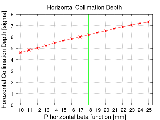
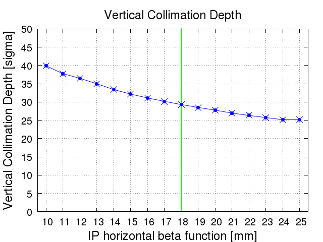
Figure 7 shows the collimation depth obtained by simulation. As is seen, the collimation depth in the horizontal plane is with mm, which confirms eq.2.
Momentum Band Width
The relative beam energy spread at the IP is proportional to . It is 0.15% at =250GeV444This is the positron energy spread quoted in the TDR. The electron energy spread is larger (0.19%) because of the increase in the undulator section. Here we use the value for positron for the scaling base because the undulator effect is tiny at 45.6GeV. If the bunch length (0.3mm) is fixed, the energy spread for Z-pole operation is 0.41%. This large (relative) energy spread may cause an emittance growth in the BDS due to the chromatic effects.
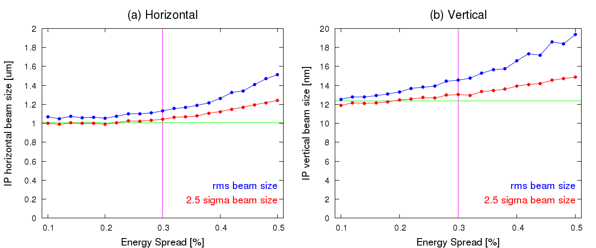
Figure 8 shows the beam sizes as functions of the energy spread. Here, the magnet errors are not included. This plot shows the beam size growth is too large if the energy spread is 0.41%.
To reduce the energy spread, we adopt a longer bunch length in the bunch compressor 0.3 0.41mm, which will bring about a smaller energy spread at the IP. The beam sizes at IP (2.5) in such a case are m (horizintal) and nm (vertical) in the absense of magnet errors and wakefields from Figure 8.
This long bunch has two side effects.
First, the transverse wake field in the main linac and the BDS increases by the factor 0.41/0.3. The previous section showed that the emittance increase in the main linac due to this reason is acceptable.
Another side effect is the increased disruption parameter at the IP. This will be mentioned in the next section.
Tuning of the BDS with magnet errors and wakefield
Simulations including the magnet errors and the process of beamline tuning were done, assuming the errors listed in Table 3.
| Bend | rotation | 100 | rad |
| field strength () | |||
| bend-to-BPM alignment | 100 | m | |
| Quad | alignment (,) | 100 | m |
| rotation | 100 | rad | |
| field strength () | |||
| sextupole component ( at =1cm) | |||
| quad-to-BPM alignment | 5 | m | |
| Sextupole | alignment (,) | 100 | m |
| rotation | 100 | rad | |
| field strength () | |||
| sext-to-BPM alignment | 5 | m |
Figure 9 shows a example of the tuning process in the presense of magnet errors (but no wake fields). It shows the vertical beam size vs. number of tuning knobs. Two cases of different r.m.s. errors of the distance from the BPM center to the quadrupole/sextupole field center (5m and 10m) are shown. 10m is the value used in the BDS simulations of ILC so far. Improvement to m during a few years of operation experience will be possible.
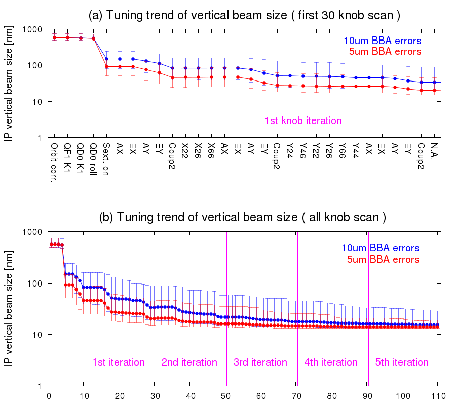
Table 4 shows the beam sizes obtained in this way. These values are averages of 100 random number seeds. The case with magnet errors and tuning is shown in the row (2).
Simulation results of the vertical beam sizes.
The offset 300m of the wake sources is used for the row (3) and (4). (m) (nm) (1) No errors 1.04 12.7 (2) Magnet errors and correction 1.12 14.0 (3) Magnet errors + static wake + correction 14.3 (4) Magnet errors + static&dynamic wake + correction 14.6
Since the beam energy is very low at the Z-pole compared with the baseline energy GeV and, moreover, we adopted the longer bunch, the effects of the transverse wake are expected to be significant.
The most important wake sources are the 107 BPMs (Beam Position Monitor) distributed over the BDS beamline. They are associated with bellows, and flange gaps. We assumed the wake sources are dislocated by 300m in the simulations.
The correction of the wake effects is done by adding artificial wake sources mounted on movers and by changing their position so as to cancell the wake effects. This is done only in the vertical plane since the effects on the horizontal plane is minor. The row (3) in Table 4 the result with static wake effects and tuning. In this simulation we assumed that the wakefields by bellows and flange gaps are minimized by using RF contacts. If not, the resulting beam size would be 15.8nm instead of 14.3nm.
In addition to the static wakefield effects described above, there is a ‘dynamic effects’ coming from the beam jitter from upstream. Since many wake sources are placed where is large and the phase advance from the IP is , the beam jitter can be enhanced by the wakefields. It is compensated for by the fast feedback system developed for the ILC. From our experience we assumed the feedback system can suppress the beam angle jitter to 10%.
The row (4) in Table 4 shows the vertical beam size in the presense of the static/dynamic wake effects and the correction. The resulting vertical beam size was 14.6nm. This is adopted in Table 1.
These simulations show that the following issues are important for the BDS tuning especially at the Z-pole.
-
•
Accurate alignment between the magnet field centers and the electric center of BPMs.
-
•
Sufficient RF contact for the bellows and flange gaps to minimize the wakes.
-
•
Relaxing the intensity dependence due to the static wake effects by wakefield knobs.
6 Beam-Beam Interaction
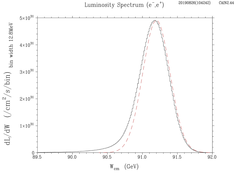
Figure.10 shows the luminosity spectrum with the parameters listed in Table 1. The dashed curve shows the initial distribution normalized at the peak. As is seen, the contibution of the beamtrahlung is very small.
Because of the longer bunch to reduce the energy spread, the vertical disruption parameter is slightly enlarged (). Nonetheless, it is still lower than the value 34.5 for GeV case. Therefore, the tolerance of the beam offset will not be severer ().
7 Luminosity Upgrade
In the present design the major limitation of the luminosity comes from the energy band-width of the final focus system and the large vertical disruption parameter.
The former may be a little improved by adopting a shorter final quadrupole magnet. In fact the TDR adopted 2m long magnet which was split into two 1m magnets. Both are excited for GeV but the upstream one is turned off for low energy operations. This helps in increasing the horizontal collimation depth from to at GeV. However, we cannot expect a large improvement of the collimation depth at the Z-pole operation by a further reduction of the magnet length, say, to 50cm.
The latter is an issue of the beam position control at the IP. Since the beamstrahlung is negligible at Z-pole, one can futher reduce the horizontal beam size in this respect, if an even larger disruption parameter is acceptable. The adoption of the so-called traveling focusing might allow a larger disruption but this is beyond the scope of this note.
On the other hand we do not forsee a major obstacle in doubling the luminosity by doubling the number of bunches from 1312 to 2625. Once the RF system is reinforced for doubled bunches, we expect to reach at Z-pole.
When ILC is extended to 500GeV, there will be a chance to adopt the scheme proposed in [2], where the 250GeV electron main linac is split into two parts, upstream part (GeV for W-pair) for the colliding beam and the downstream part (GeV with an additional electron gun) for positron production. If this possibility is to be taken into account later, some preparation is necessary for the first construction (e.g., a space for the transport line of the colliding beam).
8 Summary
We estimated the luminosity of ILC for 250GeV at the center-of-mass energy for Z-pole. In addition to the change of the horizontal emittance, which has already been announced for maximizing the luminosity at 250GeV, we made the following changes of the parameters:
-
•
Reduced the repetition rate from 5+5Hz to 3.7+3.7Hz because of the limited power consumption of the electron linac.
-
•
Increased the bunch length from 0.3mm in TDR to 0.41mm in order to reduce the beam energy spread for relaxing the issue of the momentum bandwidth of the final focus system.
-
•
Increased the from 13mm for GeV to 18mm for relaxing the requirement of the horizontal collimation.
The resulting luminosity is , which is significantly higher than the value () from the previous simple scaling in spite of the reduced repitition rate. from 250GeV in TDR.
It is presumably possible to double the luminosity when the doubled bunch option (2625 bunches) of ILC is realized.
References
-
[1]
The International Linear Collider, Technical Design Report volume 3.II:
Accelerator Baseline Design. 2013.
https://www.linearcollider.org/ILC/Publications/Technical-Design-Report -
[2]
“ILC possibilities at Z and W”, N. Walker,
http://ilcdoc.linearcollider.org/record/63004?ln=ja -
[3]
“Z-pole Operation”, LCWS2016 at Morioka,
https://agenda.linearcollider.org/event/7371/contributions/38173/ - [4] Toshihiro Matsumoto, KEK. Private communication.
-
[5]
“Overview of ILC optimization at the center of mass energy of 250GeV”, K. Yokoya, AWLC2017, June 28, 2017.
https://agenda.linearcollider.org/event/7507/timetable/#20170628.detailed,
“Preliminary study for lower horizontal emittance”, K. Kubo, AWLC2017, June 29, 2017.
https://agenda.linearcollider.org/event/7507/timetable/#20170629.detailed -
[6]
SAD is a computer program for accelerator design;
http://acc-physics.kek.jp/SAD/index.html