Inertial migration of neutrally-buoyant particles in superhydrophobic channels
Abstract
At finite Reynolds numbers particles migrate across flow streamlines to their equilibrium positions in microchannels. Such a migration is attributed to an inertial lift force, and it is well-known that the equilibrium location of neutrally-buoyant particles is determined only by their size and the Reynolds number. Here we demonstrate that the decoration of a bottom wall of the channel by superhydrophobic grooves provides additional possibilities for manipulation of neutrally-buoyant particles. It is shown that the effective anisotropic hydrodynamic slip of such a bottom wall can be readily used to alter the equilibrium positions of particles and to generate their motion transverse to the pressure gradient. These results may guide the design of novel inertial microfluidic devices for efficient sorting of neutrally-buoyant microparticles by their size.
I Introduction
Inertial microfluidic systems have been shown to be very useful for focusing and separation of microparticles of different size, density and shape with increased control and sensitivity, which is important for a wide range of applications in chemistry, biology, and medicine (Di Carlo et al., 2007; Bhagat et al., 2008; Gossett et al., 2010). Compared to classical microfluidic devices, which usually rely on relatively small flow velocities (low-Reynolds-number laminar flows), inertial microfluidics operates with higher rates when fluid inertia becomes significant. At finite Reynolds numbers particles experience an inertial lift force, which induces their migration across streamlines of carrier flow to some equilibrium positions in microchannels. Thanks to this force, the focusing of particles in inertial microfluidic devices could be achieved without applying any transverse external fields, that offers unique advantages in separation technologies. Since unlike field-flow fractionation methods, the inertial separation is based on focusing of particles at distinct equilibrium positions, but not on a difference in retention times Giddings et al. (1976, 1977) or in migration velocities Zhang et al. (1994), it can be used for a continuous fractionation of particle dispersions at high throughput (see Zhang et al. (2016); Stoecklein and Di Carlo (2018) for recent reviews). An especially challenging problem is, naturally, the fractionation of spherical neutrally-buoyant microparticles, since it can only exploit the difference in their size. Therefore, the possibilities of controlled manipulations of such particles by using an inertial lift force remain quite limited.
Inertial separation of neutrally-buoyant particles implies that they should focus at different locations, depending on their sizes. However, the dependence of the equilibrium positions on particle radii is too weak to be used in microfluidic applications. An efficient strategy for a separation of such particles on microscale is normally to balance the inertial lift force by another one, which scales differently with the particle size. This includes such external forces as electric Zhang et al. (2014) or magnetic Dutz et al. (2017). The inertial lift can also be balanced by the Dean force due to a secondary rotational flow caused by inertia of the fluid itself, which can be generated in curved channels (Di Carlo et al., 2007; Bhagat et al., 2008), leading to a migration of particles in vertical directions and altering their equilibrium positions. A promising direction is also to induce an additional force by exploiting porous channel walls. With such walls the drag to permeate flow could be used to control focusing positions of particles Altena and Belfort (1984); Lebedeva and Asmolov (2011); Garcia and Pennathur (2017).
Microfabrication has opened the possibility to elaborate channels whose surfaces are patterned in a very well controlled way, thus providing properties that they did not have when flat or slightly disordered, and the best known example of such surfaces is probably superhydrophobic (SH) ones Quere (2008). The large effective slip length (the distance within the solid at which the flow profile extrapolates to zero) of SH surfaces compared to simple, smooth channels can greatly lower the viscous drag and reduce the tendency for clogging or adhesion of suspended particles Ybert et al. (2007); Vinogradova and Belyaev (2011); Rothstein (2010). The effective hydrodynamic slip of anisotropic SH surfaces is generally tensorial Bazant and Vinogradova (2008); Feuillebois et al. (2009); Schmieschek et al. (2012), due to secondary flows transverse to the direction of the applied pressure gradient Feuillebois et al. (2010). The transverse viscous flow generated by anisotropic SH surfaces could be used to guide the controlled lateral displacement of particles and their separation by size, but these effects remain largely unexplored. Some concepts of fractionation in SH channels of low Re are known. However, their use requires a sedimentation of particles Pimponi et al. (2014); Asmolov et al. (2015), so that they cannot be used for neutrally-buoyant microparticles. In principle, SH channels can be designed to achieve inertial separations of neutrally-buoyant particles, but we are unaware of any prior work.
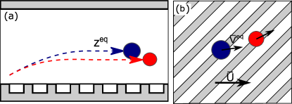
In this paper, we study an inertial migration of neutrally-buoyant spherical particles in a plane channel with the bottom wall decorated by SH grooves, tilted relative to a pressure gradient (as shown in Fig. 1). Our consideration is based on the theoretical analysis and lattice-Boltzmann simulations. We show that the effective hydrodynamic slippage of the bottom SH surface affects the migration velocity of particles and alters their equilibrium positions in the channel. We also demonstrate that particles migrate in the transverse direction with a velocity that depends on their size. Our results may guide the design of inertial microfluidic devices for efficient sorting of neutrally-buoyant microparticles by their size.
The structure of our manuscript is as follows. In Sec. II, we define our system and present some theoretical estimates of particle migration in a channel with a SH wall. Sec. III discusses our simulation method and justifies the choice of parameters. Results are discussed in Sec. IV and we conclude in Sec. V.
II Model and theoretical estimates
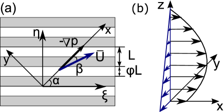
We first present the model and basic physical ideas underlying our work. We consider a viscous fluid confined between a SH plate located at and a no-slip hydrophilic plate located at and unbounded in the and directions as sketched in Fig. 2(a). The flow is driven by pressure gradient, , applied at some angle to the direction of the SH grooves. The -axis is defined along , and the -axis is aligned across the channel. The SH surface is modeled as a flat interface with alternating no-slip and perfect-slip stripes of a period and a slipping area fraction . In this idealization, we have neglected an additional mechanism for a dissipation connected with the meniscus curvature Sbragaglia and Prosperetti (2007); Teo and Khoo (2009); Asmolov et al. (2018a) which may have an influence on a channel flow.
Our final aim is to calculate translation of particles of radius in the and directions, and their migration in the direction . To evaluate these we have to know the properties of an undisturbed by particles flow field. We, therefore, first summarize and give some new interpretation of earlier results on fluid velocities in the SH channel. The maximum velocity of the Poiseuille flow in a no-slip (hydrophilic) channel of the same thickness would be , where is the dynamic viscosity. In our analysis below we use dimensionless, scaled by this value, velocities, and the channel Reynolds number is then defined as , where is the density of a fluid (and particles).
Since the Navier-Stokes equations in the SH channel can be solved only numerically, it is instructive to analyze the velocity profiles , averaged over the texture period. When , the averaged velocity in the channel satisfies tensorial slip boundary conditions at the SH wall, , where is the slip velocity at the SH surface and is the effective slip length tensor. Its eigenvalues and for the striped texture correspond to the fastest (greatest forward slip) and slowest (least forward slip) directions, along and across the stripes respectively, and depend on and Schmieschek et al. (2012). Let us now assume that at finite , the tensorial slip approach could serve as a rough approximation. If so, the averaged forward velocity profile would be approximately parabolic (see Fig. 2(b))
| (1) |
and an averaged velocity of the transverse shear flow is given by
| (2) |
Averaged forward and transverse slip velocities can be evaluated in terms of the effective slip tensor Bazant and Vinogradova (2008):
| (3) |
where the forward and transverse slip lengths are
| (4) | |||||
| (5) |
The angles and correspond then to special (eigen) directions, where and along which a secondary transverse flow is not generated, . The maximum transverse flow is generated at Vinogradova and Belyaev (2011).
It is now convenient to define a second coordinate system with the -axis directed along the stripes, and across them (see Fig. 2(a)). The reason is an undisturbed flow field, which depends only on and , is periodic in the -direction. Besides, as we report in Sec. III, our simulation cell is also periodic in the direction, so that all simulation variables will be averaged over these two coordinates. In this coordinate system, the averaged velocity field is given by
| (6) | |||||
| (7) |
At a finite channel Reynolds numbers, , the averaged velocity profile can generally differ from the parabolic one due to the presence of inertial terms in the Navier-Stokes equations. However, as we will see below in Sec. III, in reality, the deviations from the creeping-flow limit, Eqs. (1)-(5), are negligibly small even when Re.
We now turn to the motion of (force and torque free) neutrally-buoyant particles. In an unbounded linear shear flow such particles would move with the velocity , which is equal to the fluid velocity at the particle’s position . In the case of an unbounded parabolic flow, they would slightly lag the fluid due to Faxen corrections. However, the particle velocity in the channel can differ significantly from that of a fluid due to hydrodynamic interactions with the walls. It has recently been suggested that in a symmetric no-slip hydrophilic channel this difference can be characterized by the correction functions and Asmolov et al. (2018b):
| (8) |
These two functions, , should obviously become different for our SH channel due to the wall slippage and anisotropy, as well as an asymmetry of the channel itself. Note that, as shown before Davis et al. (1994); Loussaief et al. (2015); Ghalia et al. (2016), near a homogeneous slippery wall a particle has a smaller lag, , compared to the no-slip case, so that functions become close to unity. This lag should be even smaller for highly slippery SH wall.
An inertial lift force at finite Re is directed normal to the channel walls, and scales as Asmolov (1999)
| (9) |
where is the lift coefficient. The lift in a symmetric no-slip channel is an antisymmetric function of due to the flow symmetry. This function has three zeros, which correspond to equilibrium positions of particles. Two of them are stable, being symmetric and located at the vicinity of the walls. The third zero has a locus at the midplane of the channel, where the shear rate vanishes, and corresponds to an unstable equilibrium. In a SH channel the secondary transverse flow is usually much weaker than the forward flow, so that . We, therefore, could expect that the lift force will be generated mainly by the gradient of the forward velocity, similarly to a hydrophilic channel, but the locations of three equilibrium positions should be, of course, altered due to a bottom wall slip. Since the difference is expected to become smaller in the presence of the SH wall, a weaker lift force could be expected as compared with reported for a hydrophilic channel Asmolov et al. (2018b).
Finally, we expect that the transverse fluid velocity induces a lateral translation of particles. Since their equilibrium positions depend on radii, the particles of different sizes are expected to move with different transverse velocities , allowing for their spatial separation in the direction.
III Simulation method
Fluid flow and particle motion in the channel are simulated using the lattice Boltzmann method (Benzi et al., 1992; Kunert et al., 2010). We use a 3D, 19 velocity, single relaxation time implementation of the lattice Boltzmann method with a Batnagar Gross Krook (BGK) collision operator. The relaxation time is equal to throughout this paper, so that the kinematic viscosity in simulation units is . The fluid density in the initial state is set to 1 and remains approximately constant throughout the simulations. Spherical particles with radius are implemented as moving no-slip boundaries originally proposed by Ladd (Ladd and Verberg, 2001). Our implementation has been used before Kunert et al. (2010); Janoschek et al. (2010, 2014); Dubov et al. (2014); Harting et al. (2014) including a recent related article on a particle experiencing an inertial lift force in a no-slip channel Asmolov et al. (2018b).
The simulation domain has dimensions and lattice cells, which corresponds to a channel of height . Periodic boundary conditions are applied on the sides. A mid-grid bounce back no-slip boundary condition is implemented at the top wall and an on-site slip boundary condition is applied to the bottom wall to describe the striped texture Ahmed and Hecht (2009); Hecht and Harting (2010); Schmieschek et al. (2012). The stripes are parallel to the -axis and have widths (perfect slip) and (no slip) with () and varying from (no-slip) to . Since it is impossible to implement the pressure gradient explicitly in a periodic setup, we model it by applying a volumetric body force to the fluid. An equivalent force is applied to particles to ensure neutral buoyancy. The body force enters the lattice Boltzmann algorithm by shifting the equilibrium velocity in the collision operator (Shan-Chen forcing). It is applied at an angle to the stripes to maximize a transverse shear, and its magnitude is set to in simulation units. In a channel with no-slip walls this force creates a Poiseuille flow with .
Particles are released from different initial positions with a velocity equal to the average flow velocity at the corresponding height. Simulations run until the particle reaches its equilibrium position in . Typically, this takes about time steps. The equilibrium velocities and are obtained by averaging over an interval of time steps.
IV Results and discussion
In this section, we present our simulation results. More specifically, we discuss simulation data obtained for vertical and lateral displacement of particles, and also present some data on a fluid velocity field and slippage at the SH wall.
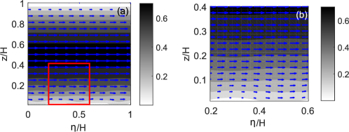
It is by no means obvious that at Re the approximate equations (1)-(5) will be accurate enough. We, therefore, first simulate the flow in a particle-free channel to characterize the unperturbed velocity field and to check the validity of formulas. A typical velocity field for a channel with a SH bottom wall is shown in Fig. 3. The fluid has a finite velocity at the slippery parts of the texture. The inhomogeneous boundary conditions result in flow ondulations near the bottom wall, but at distances comparable to the flow becomes homogeneous in the direction.
We obtain the averaged velocity profiles in the directions along and across stripes, and , by integrating the velocity field over the texture period in . The eigenvalues of effective slip lengths are then calculated as
| (10) |
Fig. 4(a) shows the effective slip lengths at the SH wall as a function of . Also included are theoretical curves obtained using the Fourier method Nizkaya et al. (2013) and valid for . We can see that the fits of our finite Re simulation data are very good. These data and theoretical calculations are used to calculate the forward and transverse slip velocities from Eqs. (3)-(5). The results are shown in Fig.4(b), and we again observe that theoretical and simulation data nearly coincide. We can, therefore, conclude that calculations based on a low Re theory provide a good description of the slip lengths and averaged slip velocities obtained in simulations.
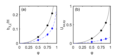
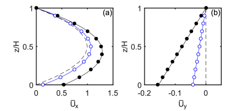
Fig. 5 plots the averaged velocity profiles in the directions and . The simulations are made using and . We can see that the forward velocity profiles are always parabolic, and that the shear rate of the secondary transverse flow is uniform throughout the channel. For similar values of , but for a flow between two misaligned striped SH walls, it has earlier been found that the creeping-flow equations are violated, and the transverse flow is suppressed by the fluid inertia Nizkaya et al. (2015). We have compared our simulation results with theoretical calculations from Eqs. (1) and (2) and see that in our case of a channel with one SH wall, the fluid inertia does not alter the and profiles. Theoretical curves for a hydrophilic channel () are also shown in Fig. 5. In the hydrophilic channel the flow is symmetric and the transverse shear is not generated. It can be seen that with the increase in fraction of the slipping area , the absolute values of forward and transverse velocities grow, and the profile becomes asymmetric with the displacement of its maximum towards a SH wall.
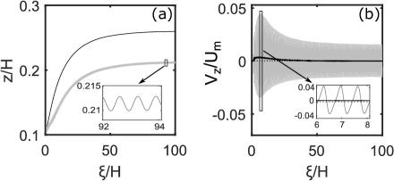
As demonstrated above (see Figs. 4 and 5), the slip velocity at the bottom wall and increases with and the transverse velocity is largest at the bottom SH wall and decreases linearly to zero at the top wall. Therefore, it is natural to expect that focusing at different neutrally buoyant particles, will translate in the transverse direction with different velocities. We now launch particles at some arbitrary and with an initial velocity equal to the averaged liquid velocity at this height, and monitor particle trajectories. This allows one to determine the particle migration velocity as a function of . Since and vanish at the same , the zeros of correspond to the focusing positions of particles. Fig. 6(a) shows trajectories of a particle of launched in the vicinity of the bottom hydrophilic and SH walls. In the case of hydrophilic no-slip wall, the particle reaches its equilibrium position after translating to a distance, roughly equal to channel width. At larger distances its -position remains nearly constant, and becomes negligibly small. When we deal with a SH bottom wall, both the particle cross-stream coordinate and the velocity oscillate about some mean values. Note that the amplitude of the velocity oscillations (shown in Fig. 6(b)) is large compared with the migration velocity for the no-slip case. This indicates that these oscillations are not due to the lift force, and are induced by the variation of the component of the fluid velocity (see Fig. 3). The oscillations in the particle position are, however, relatively small. The average particle trajectory is qualitatively similar to observed in the hydrophilic channel, but the equilibrium position is much closer to the SH wall. This is likely due to a weaker hydrodynamic interaction with a slippery wall Dubov et al. (2014).
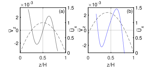
To obtain the dependence of the migration velocity on we launch particles of radius from different initial positions and, after computation of trajectories and averaging out the oscillations, obtain the results presented in Fig. 7. We recall that vanishes at equilibrium positions . In the no-slip channel (Fig. 7(a)), the migration velocity curve is similar to reported earlier for smaller particles Asmolov et al. (2018b). The flow in the channel is symmetric, leading to focusing of particles at two symmetric equilibrium positions. There is also an unstable equilibrium position located at the channel midplane. In the SH channel (Fig. 7(b)) the fluid forward flow is asymmetric and faster, with the maximum of shifted towards the slippery wall. This modifies the profile of compared with a hydrophilic channel. There are still two stable and one unstable equilibrium positions, but it is well seen that they are shifted towards the slippery wall. We remark that of an unstable position roughly coincides with the coordinate of maximum of .
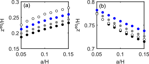
It is known that focusing positions of particles in a hydrophilic channel depend, although slightly, on their size Asmolov et al. (2018b). We now investigate the effect of particle radii on two stable in the presence of a SH wall, by varying from to and by using SH textures of , and . The simulation results are shown in Fig. 8 together with data for a hydrophilic channel. It is seen in Fig. 8(a) that the lower increases with the particle size, but decreases with , i.e. with the amplitude of the wall slip, as predicted in Sec. II. The distance of the second stable focusing position from the upper wall also increases with the particle size (see Fig. 8(b)). An unexpected result, however, is that these upper equilibrium positions are also significantly affected by the slip at the bottom wall. One can see deviations from the no-slip case even with a rather small slipping fraction, , when is relatively small, below 0.05. Another startling conclusion from this plot is that the dependence of the upper on is non-monotonous, and the equilibrium distance to the upper wall takes its minimum at .
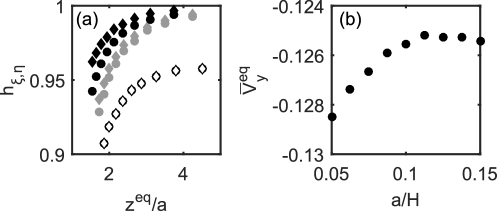
At equilibrium particles translate at a plane with a mean velocity , . This velocity can be obtained from simulation data. Then, the correction functions in Eq. (8), which characterize the difference between the average particle and fluid velocities, can be found. The results for lower equilibrium positions are presented in Fig. 9(a). The simulation data shows the correction functions grow with , and for SH channels are well above the correction for a hydrophilic channel. The deviations from increases with . We also see that is larger than , especially for the largest used in simulations. Fig. 9(b) shows the transverse component of the equilibrium velocity as a function of the particle size computed for a SH channel of . We have initially assumed that this should increase with the particle size. It is seen, however, that saturates when .
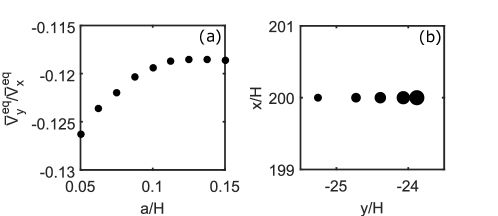
Finally, we investigate the lateral displacements of particles, which are controlled by the ratio of their forward and transverse velocities, . The dependence of this ratio on is shown in Fig. 10(a). We see that it increases when , but saturates for larger particles, indicating that particles of cannot be laterally separated. We now launch the particles at , and measure their lateral displacement at the outlet of the channel of length . The simulation results are shown in Fig. 10(b), where the size of symbols reflects the particle radius. This plot indicates that small particles are well separated by distances of the order of the channel height, which is well above the distance between them in the -direction (cf. Fig. 8), and several times greater than the particle size itself. Separation can, of course, be further improved by increasing the channel length.
V Conclusion
We have investigated the inertial migration of neutrally-buoyant particles in a plane channel with a bottom SH striped wall tilted relative to a pressure gradient. It has been shown that the flow near SH stripes is inhomogeneous and periodic, and leading to regular oscillations of the particle normal velocity and position. We have found that the SH slip significantly affects the lift force and alters all three focusing positions of neutrally buoyant particles in the channel. The lower (stable) focusing position has been shown to be significantly shifted towards the SH wall due to weaker hydrodynamic interactions. We have also demonstrated that the second stable focusing position (near upper hydrophilic wall) is also affected by the SH wall slip, and that the shift in its location is discernible even at a relatively small slipping fraction at the bottom wall, when its effective slip is moderate.
Our results show that a transverse shear flow generated by inclined SH stripes leads to a particle translation in the direction transverse to the mean (forward) flow, and that the lateral speed of small particles () increases with their size. The lateral distance between particles of different radii grows with channel length, suggesting that this can be used for their separation. It follows from our study that to separate particles by a distance of a few diameters, the channel length-to-height ratio should be around 200. For example, to separate laterally the neutrally-buoyant particles of radii and in a channel of height , the channel length should be about . However, we can conclude that it would be impossible to employ our strategy for a fractionation of larger particles.
Our work can be extended to a lateral separation of heavy particles, and one can expect that in this case the proposed concept may be even more efficient. Heavy particles may be separated not only by size, but also a density. Such particles should focus closer to the bottom wall, where the transverse shear rate is maximal, and where the difference between forward velocities of the particle and of the undisturbed flow, which strongly depends on the particle size, increases drastically. All these could potentially lead to an efficient lateral separation.
Acknowledgements.
This research was partly supported by the Russian Foundation for Basic Research (grant 18-01-00729), the Ministry of Science and Higher Education of the Russian Federation and by the German Research Foundation (grant HA 4382/8-1).References
- Di Carlo et al. (2007) D. Di Carlo, D. Irimia, R.G. Tompkins, and M. Toner, “Continuous inertial focusing, ordering, and separation of particles in microchannels,” Proc. Natl. Acad. Sci. USA 104, 18892–18897 (2007).
- Bhagat et al. (2008) A. A. S. Bhagat, S. S. Kuntaegowdanahalli, and I. Papautsky, “Continuous particle separation in spiral microchannels using dean flows and differential migration,” Lab. Chip 8, 1906–1914 (2008).
- Gossett et al. (2010) D. R. Gossett, W. M. Weaver, A. J. Mach, S. C. Hur, H. T. K. Tse, W. Lee, H. Amini, and D. Di Carlo, “Label-free cell separation and sorting in microfluidic systems,” Anal. Bioanal. Chem. 397, 3249–3267 (2010).
- Giddings et al. (1976) J. C. Giddings, F. J. Yang, and M. N. Myers, “Theoretical and experimental characterization of flow field-flow fractionation,” Anal. Chem. 48, 1126–1132 (1976).
- Giddings et al. (1977) J. C. Giddings, F. J. Yang, and M. N.. Myers, “Correction - theoretical and experimental characterization of field-flow fractionation,” Anal. Chem. 49, 523–523 (1977).
- Zhang et al. (1994) Jue Zhang, P Stephen Williams, Marcus N Myers, and J Calvin Giddings, “Separation of cells and cell-sized particles by continuous splitt fractionation using hydrodynamic lift forces,” Separation science and technology 29, 2493–2522 (1994).
- Zhang et al. (2016) J. Zhang, S. Yan, D. Yuan, G. Alici, N.-T. Nguyen, M. E. Warkiani, and W. Li, “Fundamentals and applications of inertial microfluidics: a review,” Lab. Chip 16, 10–34 (2016).
- Stoecklein and Di Carlo (2018) D. Stoecklein and D. Di Carlo, “Nonlinear microfluidics,” Anal. Chem. 91, 296–314 (2018).
- Zhang et al. (2014) J. Zhang, S. Yan, G. Alici, N.-T. Nguyen, D. Di Carlo, and W. Li, “Real-time control of inertial focusing in microfluidics using dielectrophoresis (dep),” RSC Adv. 4, 62076–62085 (2014).
- Dutz et al. (2017) S. Dutz, M.E. Hayden, and U.O. Häfeli, “Fractionation of magnetic microspheres in a microfluidic spiral: Interplay between magnetic and hydrodynamic forces,” PLOS ONE 12, e0169919 (2017).
- Altena and Belfort (1984) F. W. Altena and G. Belfort, “Lateral migration of spherical particles in porous flow channels: application to membrane filtration,” Chem. Eng. Sci. 39, 343–355 (1984).
- Lebedeva and Asmolov (2011) N. A. Lebedeva and E. S. Asmolov, “Migration of settling particles in a horizontal viscous flow through a vertical slot with porous walls,” Int. J. Multiph. Flow 27, 453–461 (2011).
- Garcia and Pennathur (2017) M. Garcia and S. Pennathur, “Inertial particle dynamics in the presence of a secondary flow,” Phys. Rev. Fluids 2, 042201 (2017).
- Quere (2008) D. Quere, “Wetting and roughness,” Annu. Rev. Mater. Res. 38, 71–99 (2008).
- Ybert et al. (2007) C. Ybert, C. Barentin, C. Cottin-Bizonne, P. Joseph, and L. Bocquet, “Achieving large slip with superhydrophobic surfaces: Scaling laws for generic geometries,” Phys. Fluids 19, 123601 (2007).
- Vinogradova and Belyaev (2011) O. I. Vinogradova and A. V. Belyaev, “Wetting, roughness and flow boundary conditions,” J. Phys.: Condens. Matter 23, 184104 (2011).
- Rothstein (2010) J. P. Rothstein, “Slip on superhydrophobic surfaces,” Annu. Rev. Fluid Mech. 42, 89–109 (2010).
- Bazant and Vinogradova (2008) M. Z. Bazant and O. I. Vinogradova, “Tensorial hydrodynamic slip,” J. Fluid Mech. 613, 125–134 (2008).
- Feuillebois et al. (2009) F. Feuillebois, M. Z. Bazant, and O. I. Vinogradova, “Effective slip over superhydrophobic surfaces in thin channels,” Phys. Rev. Lett. 102, 026001 (2009).
- Schmieschek et al. (2012) S. Schmieschek, A. V. Belyaev, J. Harting, and O. I. Vinogradova, “Tensorial slip of super-hydrophobic channels,” Phys. Rev. E 85, 016324 (2012).
- Feuillebois et al. (2010) F. Feuillebois, M. Z. Bazant, and O. I. Vinogradova, “Transverse flow in thin superhydrophobic channels,” Phys. Rev. E 82, 055301(R) (2010).
- Pimponi et al. (2014) D. Pimponi, M. Chinappi, P. Gualtieri, and C. M. Casciola, “Mobility tensor of a sphere moving on a superhydrophobic wall: application to particle separation,” Microfluid Nanofluid 16, 571–585 (2014).
- Asmolov et al. (2015) E. S. Asmolov, A. L. Dubov, T. V. Nizkaya, A. J. C. Kuehne, and O. I. Vinogradova, “Principles of transverse flow fractionation of microparticles in superhydrophobic channels,” Lab. Chip 15, 2835–2841 (2015).
- Sbragaglia and Prosperetti (2007) M. Sbragaglia and A. Prosperetti, “A note on the effective slip properties for microchannel flows with ultrahydrophobic surfaces,” Phys. Fluids 19, 043603 (2007).
- Teo and Khoo (2009) C. Teo and B. Khoo, “Analysis of Stokes flow in microchannels with superhydrophobic surfaces containing a periodic array of micro-grooves,” Microfluid Nanofluid 7, 353 (2009).
- Asmolov et al. (2018a) E. S. Asmolov, T. V. Nizkaya, and O. I. Vinogradova, “Enhanced slip properties of lubricant-infused grooves,” Phys. Rev. E 98, 033103 (2018a).
- Asmolov et al. (2018b) E. S. Asmolov, A. L. Dubov, T. V. Nizkaya, J. Harting, and O. I. Vinogradova, “Inertial focusing of finite-size particles in microchannels,” J. Fluid Mech. 840, 613–630 (2018b).
- Davis et al. (1994) A. M. J. Davis, M. T. Kezirian, and H. Brenner, “On the Stokes-Einstein model of surface diffusion along solid surfaces: Slip boundary conditions,” J. Colloid Interface Sci. 165, 129–140 (1994).
- Loussaief et al. (2015) H. Loussaief, L. Pasol, and F. Feuillebois, “Motion of a spherical particle in a viscous fluid along a slip wall,” Q. J. Mech. Appl. Math. 68, 115–144 (2015).
- Ghalia et al. (2016) N. Ghalia, F. Feuillebois, and A. Sellier, “A sphere in a second degree polynomial creeping flow parallel to a plane, impermeable and slipping wall,” Q. J. Mech. Appl. Math. 69, 353–390 (2016).
- Asmolov (1999) E. S. Asmolov, “The inertial lift on a spherical particle in a plane Poiseuille flow at large channel Reynolds number,” J. Fluid Mech. 381, 63–87 (1999).
- Benzi et al. (1992) R. Benzi, S. Succi, and M. Vergassola, “The lattice Boltzmann equation: theory and applications,” Physics Reports 222, 145 (1992).
- Kunert et al. (2010) C. Kunert, J. Harting, and O. I. Vinogradova, “Random-roughness hydrodynamic boundary conditions,” Phys. Rev. Lett. 105, 016001 (2010).
- Ladd and Verberg (2001) A. J. C. Ladd and R. Verberg, “Lattice-Boltzmann simulations of particle-fluid suspensions,” J. Stat. Phys. 104, 1191 (2001).
- Janoschek et al. (2010) F. Janoschek, F. Toschi, and J. Harting, “Simplified particulate model for coarse-grained hemodynamics simulations,” Phys. Rev. E 82, 056710 (2010).
- Janoschek et al. (2014) F. Janoschek, J. Harting, and F. Toschi, “Towards a continuum model for particle-induced velocity fluctuations in suspension flow through a stenosed geometry,” Int. J. Modern Physics C 25, 1441013 (2014).
- Dubov et al. (2014) A. L. Dubov, S. Schmieschek, E. S. Asmolov, J. Harting, and O.I. Vinogradova, “Lattice-Boltzmann simulations of the drag force on a sphere approaching a superhydrophobic striped plane,” J. Chem. Phys. 140, 034707 (2014).
- Harting et al. (2014) J. Harting, S. Frijters, M. Ramaioli, M. Robinson, D. E. Wolf, and S. Luding, “Recent advances in the simulation of particle-laden flows,” Eur. Phys. J. Spec. Topics 223, 2253–2267 (2014).
- Ahmed and Hecht (2009) N. K. Ahmed and M. Hecht, “A boundary condition with adjustable slip length for lattice boltzmann simulations,” J. Stat. Mech. Theory Exp. 2009, 09017 (2009).
- Hecht and Harting (2010) M. Hecht and J. Harting, “Implementation of on-site velocity boundary conditions for d3q19 lattice boltzmann simulations,” J. Stat. Mech. Theory Exp. 2010, P01018 (2010).
- Nizkaya et al. (2013) T. V. Nizkaya, E. S. Asmolov, and O. I. Vinogradova, “Flow in channels with superhydrophobic trapezoidal textures,” Soft Matter 9, 11671–11679 (2013).
- Nizkaya et al. (2015) T. V. Nizkaya, E. S. Asmolov, J. Zhou, F. Schmid, and O. I. Vinogradova, “Flows and mixing in channels with misaligned superhydrophobic walls,” Phys. Rev. E 91, 033020 (2015).