Vortex Shear Banding Transitions in Superconductors with Inhomogeneous Pinning Arrays
Abstract
We numerically examine the flow of superconducting vortices in samples containing square pinning arrays in which a band of pins is removed. When a drive is applied at an angle with respect to the band orientation, we find that the vortex depinning initiates in the pin-free channel. The moving vortices form a series of quasi-one-dimensional shear bands that begin flowing in the bulk of the pin-free channel, and the motion gradually approaches the edge of the pinned region. The consecutive depinning of each shear band appears as a series of jumps in the velocity-force curves and as sharp steps in the spatial velocity profiles. When a constant drive is applied parallel to the pin-free channel along with a gradually increasing perpendicular drive, the net vortex velocity decreases in a series of steps that correspond to the immobilization of bands of vortices, and in some cases the flow can drop to zero, creating a field effect transistor phenomenon. These results should also be relevant to other types of systems that exhibit depinning in the presence of inhomogeneous pinning.
1 Introduction
When a solid is subjected to a shear force, the dynamic response can be characterized by constructing a stress-strain curve. As the strain increases from zero, the system remains in a solid state with a linearly growing stress, and when the strain is large enough, the system yields and starts to flow as bonds between the constituent particles break. In many cases, for strains above yielding, the stress saturates or even decreases with increasing strain [1, 2, 3]. Yielding can occur via shear banding or shear localization, in which only a portion of the sample is moving while other portions remain stationary, or it can occur via the development of a smooth velocity gradient throughout the sample [4, 5]. The behavior at yielding varies depending on the rate of change of the strain as well as on whether the system is crystalline, polycrystalline, or amorphous.
Another phenomenon that has similarities to the yielding transition is the depinning transition for a collection of particles driven over a random or periodic substrate [6, 7]. Under an increasing drive, the system can remain pinned until a critical drive is reached above which flow initiates. The motion can be elastic, with each particle maintaining the same neighbors, or plastic, with continuous rearrangements of the particles. When the substrate is composed of pinning sites, individual particles can be trapped directly at the pinning sites or indirectly through interactions with pinned particles. For solids undergoing yielding, it is only particle-particle interactions that produce resistance to flow, and in materials with a higher shear modulus, a larger force must be applied in order to induce yielding. In some cases, systems that undergo depinning can also exhibit a yielding transition, such as vortices in type-II superconductors in a Corbino geometry, which exerts a nonuniform force on the vortex lattice [8, 9, 10, 11, 12, 13]. If the vortices remain elastic and rotate as a solid object, the velocity of an individual vortex increases linearly with its distance from the center of the disk. If plastic flow occurs instead, the vortices disorder, exhibit liquid behavior, and have a velocity that decays as . Both of these behaviors have been observed in experiment [8] and simulations [9]. The simulations indicate that there is a critical current or rotation rate required to induce a transition to the plastic flow state, which is accompanied by the proliferation of topological defects in the vortex structure [9, 14]. Since the vortices form a triangular lattice in the absence of pinning, shear banding can also occur in which a band of vortices flow together as a rigid body at one velocity while other bands of vortices flow at different velocities, and there can be locking and unlocking transitions between the different moving bands due to the spatial periodicity of the vortices. Simulations by Lin et al. showed dynamical locking and dynamical commensurability effects for vortices in mesoscale Corbino disks [15]. Experiments by Okuma et al. for vortices in a Corbino geometry with an additional ac drive produced Shapiro steps, interpreted as resulting from a shear banding effect in which vortices near the center of the sample depin first, followed by laminar flow at higher drives [12, 16]. There are also studies of shearing effects for vortices interacting with pinning sites inside a Corbino geometry [17] or with a single easy flow channel embedded in strong pinning [18]. For inhomogeneous pinning, composed of a region of strong pinning coexisting with a channel of weak or no pinning, the vortices in the weakly pinned channel move first under an applied drive, forming a velocity gradient with the fastest flow at the center of the weakly pinned channel and zero flow at the edge of the more strongly pinned region [19, 20]. Another particle-based system in which similar shear effects can occur is a rotating ring of trapped colloidal particles embedded in a background of free particles, where the relative motion of the background particles exterior or interior to the moving ring can be measured. Experiments performed with this geometry also reveal laning or shear banding effects [21, 22, 23].
In this work we use numerical simulations to show that vortex shear banding can be achieved without a Corbino geometry and with a uniform drive when the substrate consists of a strip of strong pinning coexisting with a pin-free channel. We focus on a square pinning array in which a group of adjacent rows of pins have been removed. Such a substrate could be created experimentally using artificial pinning structures [24, 25, 26, 27], patterned irradiation [28], or controlled thickness modulations [29, 30, 31, 32, 33]. The vortices in the pin-free channel easily depin as an elastic solid under a parallel applied driving force. When the drive is applied at an angle with respect to the pin-free channel, we find strong shear banding effects, with flow initially occurring only at the center of the pin-free channel and the vortices near the edges of the channel remaining immobile. As the drive increases, a series of shear banding transitions occur as additional rows of vortices in the pin-free channel depin, producing signature jumps in the velocity-force curves and steps in the spatial velocity profile. Under a constant parallel drive and gradually increasing perpendicular drive, the longitudinal velocity passes through a series of drops as the shear banding effects become stronger until there is a transition to a state in which the vortices flow in both the parallel and perpendicular directions. Interestingly, the flow of vortices within the pinned portion of the sample in this case is strictly in the perpendicular direction due to a dynamical symmetry locking with the square pinning array. Under some conditions, we find that application of a perpendicular drive can send the longitudinal velocity sharply to zero, similar to a field effect transistor in which the current response changes sharply under an applied field. Our results could be tested in superconductors with artificial pinning arrays where a portion of the pinning sites have been removed, in samples with a step in the sample thickness, or in systems with a gradient in the pinning density or strength [27, 34, 35]. Although our results are for a vortex system, they should be general to other particle like systems where spatially inhomogeneous pinning can arise, such as skyrmions in chiral magnets and colloidal systems.
2 Simulation
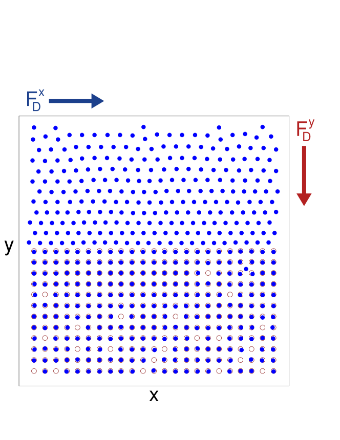
We consider a superconducting system with a square pinning lattice of lattice constant where half the pinning sites are removed and vortices are present, as illustrated in Fig. 1. We use a rigid vortex approximation in which the dynamics of vortex is governed by the following overdamped equation of motion:
| (1) |
The damping constant is , which we set equal to unity. The vortex-vortex interactions are repulsive and the sum of the vortex-vortex forces on vortex is . Here is the modified Bessel function which decays monotonically, is the distance between vortices and , , is the penetration depth, , is the flux quantum, and is the permittivity. The pinning sites are modeled as parabolic traps of radius and force . Here is the Heaviside step function, is the maximum force exerted by the pinning site, is the location of pinning site , , and . All forces are measured in units of and lengths in units of . We choose the vortex density such that the number of vortices would match the number of pinning sites if the entire pinning lattice were present, , where is the matching field for the full pinning array. Since half of the pinning sites are missing, our vortex density is , where is the matching field for the half pinning array. We set the pinning density to . The net drive is applied at an angle to the axis and is given by .
The initial vortex positions are obtained using a simulated annealing protocol in which we start at a high temperature with the vortices in a liquid state and slowly cool the sample to . After the initialization, we apply a driving force that is increased in increments of . We spend 20000 simulation time steps at each increment to ensure that the system has reached a steady state, and we measure the average vortex velocities in the parallel, , and perpendicular, , directions. We focus on the case and consider a range of drives over which depinning of the vortices trapped at the pinning sites is negligible. This model has previously been used to study vortex pinning and dynamics in systems with uniform pinning or conformal pinning arrays, where commensurability and enhanced pinning effects appear [34, 36, 37, 38].
3 Vortex Banding
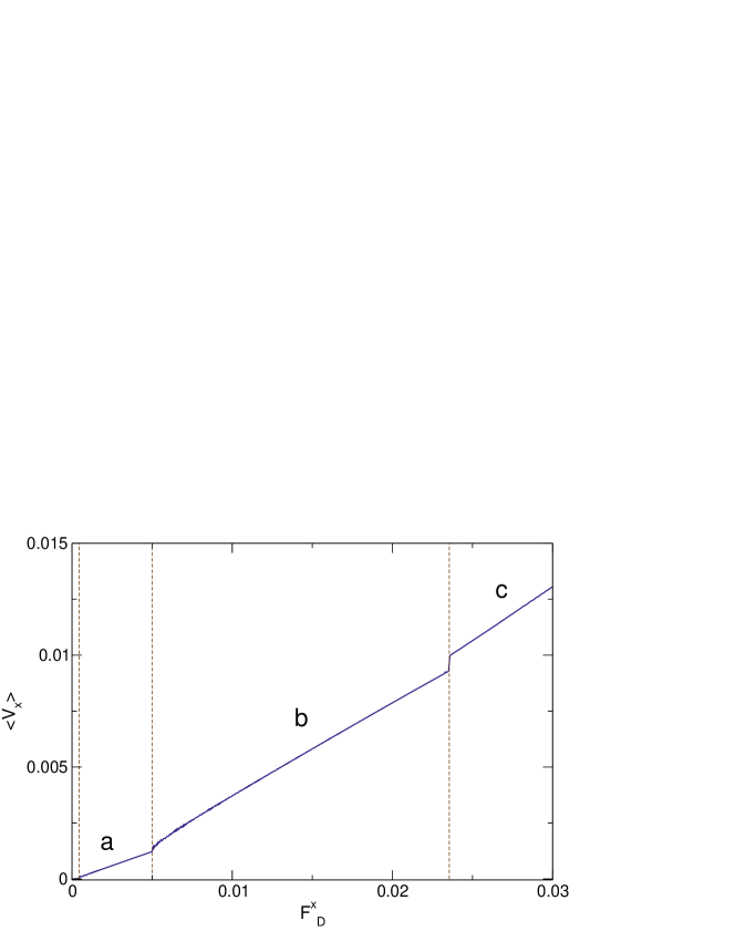
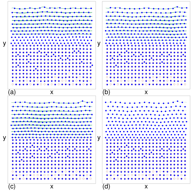
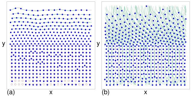
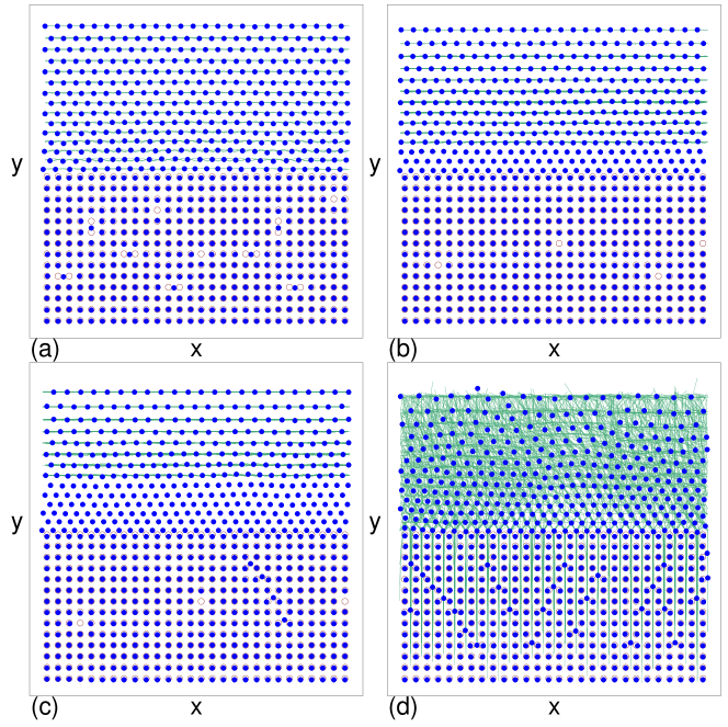
Figure 1 illustrates the sample geometry with , where almost all of the pinning sites are occupied. The arrows indicate the direction of the driving forces and , which give a net drive magnitude of applied at an angle to the axis. In Fig. 2 we plot versus for the system in Fig. 1 at a fixed . The velocity-force curve shows three jumps that correspond to transitions between different vortex flow patterns. For , the system is in a pinned state and the vortices in the pin-free channel are trapped by the interactions with the pinned vortices along the edges of the channel. For , shear banded flow occurs as illustrated in Fig. 3(a) for , where there are three rows of immobile vortices just above the pinned region. This is followed by an upward jump in at to a state in which there is only a single row of immobile vortices in the pin-free channel, as shown in Fig. 3(b) at . This flow state persists over the range , after which another upward jump in occurs and all of the vortices in the pin-free channel flow, as shown in Fig. 3(c) at . For increasing perpendicular drive , we find that the number of immobile rows in the pin-free channel increases, as illustrated in Fig. 3(d) for a sample with at , just above depinning, where four rows of vortices are motionless.
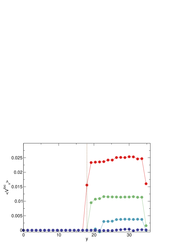
In Fig. 4 we plot the spatial average velocity profiles vs for the system in Fig. 2 for the four different phases. The local average velocity is given by , where and . In the pinned state at , is zero across the entire system, while at where there are three immobile rows in the pin-free channel, there is a step in the velocity at the edge of the flowing band of vortices. The velocity is not uniform across the flowing band but is slightly smaller next to the immobile rows, and we find that the outer moving row undergoes a phase slip with respect to the remaining moving rows. At , where there is one immobile row in the pin-free channel, the band of finite has extended nearly to the boundary of the pinning region, and the velocity of the outer moving row is again lower than that of the rest of the moving band. At , all of the vortices in the pin-free channel are moving and the band of finite reaches its widest extent, but the vortex rows closest to the pinning continue to move more slowly than the other vortices. The drop in at large is due to the presence of the pinned region on the other side of the periodic boundary. We note that for all of these values of , is zero.
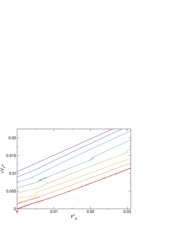
We now introduce some terminology for the different states. We denote the pinned state as phase P, while in phase M, all of the rows in the pin-free channel are flowing. In phase I, there is one immobile row of vortices in the pin-free channel, in phase III, there are three immobile rows, and so forth. For the parameters considered here, we have not observed a situation in which there are two immobile rows in the pin-free channel. In Fig. 5 we plot a series of versus curves for , , , , , , , and . At , there is only a single transition from the pinned phase P to phase M in which all the vortices in the pin-free channel are moving. For , the pinned phase P is followed first by phase III and then by phase M, while for , the sequence of states is phase P to phase III to phase I to phase M. When , the system transitions from the pinned phase P to phase IV in which there are four immobile vortex rows, followed by phase I and then by phase M, which appears near . At , we find a transition from phase P to phase V, where there are five pinned rows of interstitial vortices as illustrated in Fig. 6(a). A transition to phase I occurs at a much higher drive of . For , the pinned phase P is lost and the system is initially in a random guided flow, where the particles flow in both the and directions in the pin-free channel but in only the direction in the pinned region. This state is illustrated in Fig. 6(b) for a system with and . For sufficiently large , the system can transition from phase R to phase I, but when , the system remains in phase R and there are never immobile vortex rows in the pin-free channel.
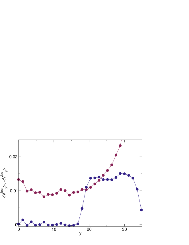
To further characterize the phase R flow, in Fig. 7 we plot the spatial velocity profiles and versus for the flow pattern illustrated in Fig. 6(b). Within the pinned region, the vortices are moving strictly in the -direction, while in the pin-free channel, the vortices are moving in both the and directions. We note that the curve has been reduced by a factor of two for clarity.
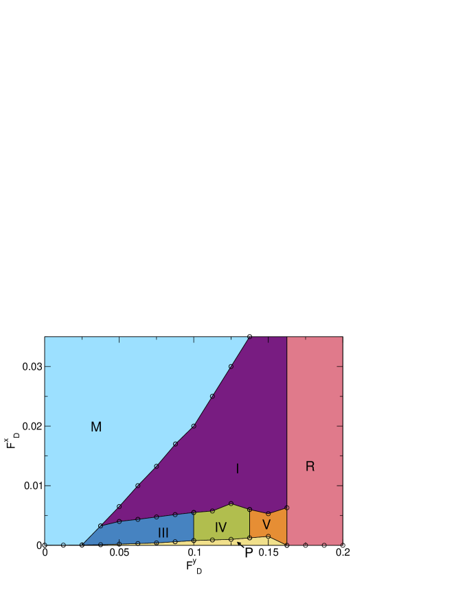
In Fig. 8 we plot the dynamic phase diagram as a function of versus for the system from Fig. 6, highlighting the pinned phase P, phases I, III, IV, and V, phase M in which all vortices in the pin-free channel are moving, and the random guided flow phase R. We note that for finer intervals of or a larger system, there will likely be additional phases corresponding to six, seven, and higher numbers of immobile vortex rows in the pin-free channel. For higher values of than what is considered here, there are additional phases that occur when the vortices at the pinning sites begin to depin, which is beyond the scope of this work. We also note that in general we do not observe a continuous velocity gradient in our system. This is probably a result of the triangular ordering of the vortices within the pin-free channel, which causes the system to behave like a sheared triangular solid breaking along its easy shear direction. If the system were in a liquid or amorphous state, it could be possible to obtain a continuous velocity gradient with no well-defined shear bands.
4 Shearing Dynamics for Perpendicular Driving and Field Effect Transistor
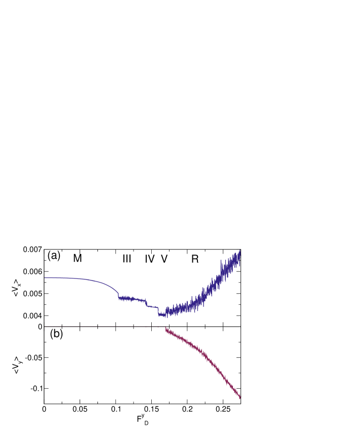
We next consider the case where the driving force along the or parallel direction is fixed while the drive along the or perpendicular direction increases. Although the net force is increasing, the net velocity generally decreases in a series of steps as more rows of vortices become immobile. In Fig. 9 we plot and versus for the same system in Fig. 2 at fixed . When , the system is in phase M, with all the vortices in the pin-free channel flowing. As increases, gradually decreases, with a downward jump near marking the transition into phase III. This is followed by two more drops in at the transitions into phases IV and V, and at , the system enters phase R, where becomes finite and the velocities in both directions show large fluctuations. In phase R, begins to increase with increasing . For other values of , we observe a similar trend with drops in marking the transitions among different phases; however, for this pinning density, we do not find a phase in which goes to zero. For denser pinning, it is more difficult for the vortices to enter the pinned region, and it is possible to observe a reentrant pinning effect.
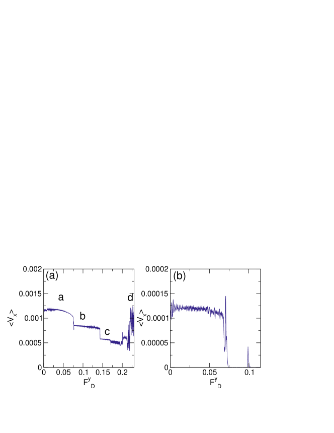
In Fig. 10(a) we plot versus for a system with fixed but denser pinning of at the same filling of . For , the system is in phase M with all the vortices in the pin-free channel flowing, as illustrated in Fig. 11(a) at . There is a jump down in at the transition to a phase in which there are three immobile rows of vortices in the pin-free channel, which appears over the range and is illustrated in Fig. 11(b) for . When , there are six immobile vortex rows in the pin-free channel, as shown in Fig. 11(c) at . For , an upward jump in is accompanied by a transition to a state with five immobile vortex rows in the pin-free channel. At higher , the system enters region R, as illustrated in Fig. 11(d) at , where the vortices only flow along the direction within the pinning region.
In Fig. 10(b) we plot versus for the same system as in Fig. 10(a) but at a smaller value of . Here the system is initially in phase M before transitioning to a pinned state with . Eventually, when is large enough (not shown), the system enters phase R flow. The sharp drop down in the velocity at the onset of phase P is similar to what is observed in a field effect transition, where an increase in driving can cause a sharp transition in the current flow, or the vortex flow in this case. In general, as the density of pinning sites increases, the range of driving over which this field effect transistor phenomenon occurs becomes wider.
5 Summary
We numerally examine vortices in a system with a square pinning array where half of the pinning sites have been removed to form a pin-free channel. When a drive is applied at an angle with respect to the channel, we find that the vortices in the channel depin in a series of transitions among different shear banded flow phases. The vortex velocity exhibits a sequence of steps corresponding to the quantization of the number of rows of moving vortices. As the component of the driving force parallel to the channel increases, the depinning of individual rows of vortices produces steps in the velocity-force curve. When the component of the driving force perpendicular to the channel increases, the number of immobile vortex rows in the pin-free channel also increases. A gradient in the velocity of the moving vortices appears in the pin-free channel, with vortices close to the edge of the channel moving more slowly than those in the center of the channel. When the perpendicular drive is large enough, there is a transition to a state in which the vortices move both parallel and perpendicular to the pin-free channel; however, the vortices within the pinned part of the sample move only perpendicular to the orientation of the pin-free channel. If the parallel driving force is fixed and the perpendicular driving force is increased, we find a series of downward steps in the longitudinal velocity as the number of immobile vortex rows increases, and in some cases it is even possible for the increasing perpendicular drive to produce a complete suppression of vortex motion in a field effect transistor phenomenon. In addition to vortices, our results should be general to other particle-based systems with inhomogeneous pinning, such as colloids and skyrmions.
References
References
- [1] Beer F, Johnston R, Dewolf J and Mazurek D 2009 Mechanics of Materials (McGraw-Hill, New York)
- [2] Argon A S 1979 Acta Metallurg. 27 47–58
- [3] Regev I, Lookman T and Reichhardt C 2013 Phys. Rev. E 88(6) 062401
- [4] Cohen I, Davidovitch B, Schofield A B, Brenner M P and Weitz D A 2006 Phys. Rev. Lett. 97(21) 215502
- [5] Alix-Williams D D and Falk M L 2018 Phys. Rev. E 98(5) 053002
- [6] Fisher D S 1998 Phys. Rep. 301(1-3) 113–150
- [7] Reichhardt C and Reichhardt C J O 2017 Rep. Prog. Phys. 80(2) 026501
- [8] López D, Kwok W K, Safar H, Olsson R J, Petrean A M, Paulius L and Crabtree G W 1999 Phys. Rev. Lett. 82(6) 1277–1280
- [9] Benetatos P and Marchetti M C 2002 Phys. Rev. B 65(13) 134517
- [10] Miguel M C and Zapperi S 2003 Nature Mater. 2(7) 477–481
- [11] Furukawa A and Nisikawa Y 2006 Phys. Rev. B 73(6) 064511
- [12] Okuma S, Yamazaki Y and Kokubo N 2009 Phys. Rev. B 80(22) 220501
- [13] Cabral L R E, de Aquino B R C H T, Silva C C d S, Milošević M V and Peeters F M 2016 Phys. Rev. B 93(1) 014515
- [14] Miguel M C, Mughal A and Zapperi S 2011 Phys. Rev. Lett. 106(24) 245501
- [15] Lin N S, Misko V R and Peeters F M 2009 Phys. Rev. Lett. 102(19) 197003
- [16] Kawamura Y, Matsumura Y, Yamazaki Y, Kaneko S, Kokubo N and Okuma S 2015 Supercond. Sci. Technol. 28(4) 045002
- [17] Rosen Y J, Guénon S and Schuller I K 2013 Phys. Rev. B 88(17) 174511
- [18] Reichhardt C and Reichhardt C J O 2010 Phys. Rev. B 81(10) 100506
- [19] Marchetti M C and Nelson D R 1999 Phys. Rev. B 59(21) 13624–13627
- [20] Marchetti M C and Nelson D R 2000 Physica C 330(3-4) 105–129
- [21] Buttinoni I, Zell Z A, Squires T M and Isa L 2015 Soft Matter 11(42) 8313–8321
- [22] Williams I, Oguz E C, Speck T, Bartlett P, Löwen H and Royall C P 2016 Nature Phys. 12(1) 98–U134
- [23] Ortiz-Ambriz A, Gerloff S, Klapp S H L, Ortin J and Tierno P 2018 Soft Matter 14(24) 5121–5129
- [24] Baert M, Metlushko V V, Jonckheere R, Moshchalkov V V and Bruynseraede Y 1995 Phys. Rev. Lett. 74 3269–3272
- [25] Martín J I, Vélez M, Nogués J and Schuller I K 1997 Phys. Rev. Lett. 79(10) 1929–1932
- [26] Trastoy J, Malnou M, Ulysse C, Bernard R, Bergeal N, Faini G, Lesueur J, Briatico J and Villegas J E 2014 Nature Nanotechnol. 9(9) 710–715
- [27] Wang Y L, Latimer M L, Xiao Z L, Divan R, Ocola L E, Crabtree G W and Kwok W K 2013 Phys. Rev. B 87(22) 220501
- [28] Banerjee S S, Soibel A, Myasoedov Y, Rappaport M, Zeldov E, Menghini M, Fasano Y, de la Cruz F, van der Beek C J, Konczykowski M and Tamegai T 2003 Phys. Rev. Lett. 90(8) 087004
- [29] Besseling R, Niggebrugge R and Kes P H 1999 Phys. Rev. Lett. 82(15) 3144–3147
- [30] Guillamón I, Córdoba R, Sesé J, De Teresa J M, Ibarra M R, Viera S and Suderow H 2014 Nature Phys. 10(11) 851–856
- [31] Dobrovolskiy O, Bevz V, Begun E, Sachser R, Vovk R and Huth M 2019 Phys. Rev. Applied 11(5) 054064
- [32] Dobrovolskiy O V, Shklovskij V A, Hanefeld M, Zörb M, Köhs L and Huth M 2017 Supercond. Sci. Technol. 30(8) 085002
- [33] Dobrovolskiy O V, Hanefeld M, Zörb M, Huth M and Shklovskij V A 2016 Supercond. Sci. Technol. 29(6) 065009
- [34] Ray D, Olson Reichhardt C J, Jankó B and Reichhardt C 2013 Phys. Rev. Lett. 110(26) 267001
- [35] Guenon S, Rosen Y J, Basaran A C and Schuller I K 2013 Appl. Phys. Lett. 102(25) 252602
- [36] Reichhardt C and Reichhardt C J O 2007 Phys. Rev. B 76(6) 064523
- [37] Reichhardt C and Reichhardt C J O 2007 Phys. Rev. B 76(9) 094512
- [38] Reichhardt C and Olson Reichhardt C J 2008 Phys. Rev. B 78(18) 180507