New efficient flat-back 3D gadgets in origami extrusions compatible with the conventional pyramid-supported 3D gadgets
Abstract. An origami extrusion is a folding of a D object in the middle of a flat piece of paper, using D gadgets which create faces with solid angles. Our main concern is to make origami extrusions of polyhedrons using D gadgets with simple outgoing pleats, where a simple pleat is a pair of a mountain fold and a valley fold which are parallel to each other. In this paper we present a new type of D gadgets with simple outgoing pleats in origami extrusions and their construction. Our D gadgets are downward compatible with the conventional pyramid-supported gadgets developed by Calros Natan as a generalization of the cube gadget, in the sense that in many cases we can replace the conventional gadgets with the new ones with the same outgoing pleats while the converse is not always possible. We can also change angles of the outgoing pleats under certain conditions. Unlike the conventional pyramid-supported D gadgets, the new ones have flat back sides above the ambient paper, and thus we can make flat-foldable origami extrusions. Furthermore, since our new D gadgets are less interfering with adjacent gadgets than the conventional ones, we can use wider pleats at one time to make the extrusion higher. For example, we prove that the maximal height of the prism of any convex polygon (resp. any triangle) that can be extruded with our new gadgets is more than times (resp. times) of that with the conventional ones. We also present explicit constructions of division/repetition and negative versions of the new D gadgets.
1. Introduction
There are many studies on folding D objects from a flat piece of paper. In particular, E. Demaine, M. Demaine and Mitchell proved in [4] that any polyhedron can be folded from a piece of paper, and a practical software package for designing the crease pattern of any polyhedron was developed by E. Demaine and Tachi [5].
In this paper we are concerned with origami extrusions, which are a different type of D origami. An origami extrusion is a folding of a D object in the middle of a flat piece of paper, using D gadgets which create faces with solid angles. Among many kinds of D gadgets known in origami extrusions, the cube gadget, four copies of which are shown in Figure 1.2, was independently discovered by David Huffman and other paper folders, which creates the top and two vertical faces of a cube, where the side faces created are supported by a triangular pyramid from inside (see [1], in which this cube gadget is referred to as the gadget). In [1], Benbernou, E. Demaine, M. Demaine, and Ovadyr studied origami extrusions of polycubes introducing three kinds of cube gadgets including the above one. Also, E. Demaine, M. Demaine and Ku extruded in [3] any orthogonal maze introducing six kinds of vertex gadgets. Notably, Carlos Natan generalized in [8] the pyramid-supported cube gadget to one which creates a top face parallel to the ambient paper, and two side faces in a general position which share a ridge. In each of Natan’s D gadgets, a triangular pyramid supports from inside the two side faces created, and the side faces do not attach to each other directly, the ridge between which we can see the inside space.
A common feature of the above D gadgets is that they have simple outgoing pleats, where a simple pleat is a pair of a mountain fold and a valley fold which are parallel to each other. In origami extrusions, the use of D gadgets with simple outgoing pleats is of great advantage to successive extrusions because the paper remains flat outside the extruded object after the folding. See also Cheng’s paper [2] for examples of successive extrusions. Simple outgoing pleats have another advantage in making origami D tessellations in which adjacent extrusions share some of their outgoing pleats.
Our main concern is to make origami extrusions of polyhedrons using D gadgets with simple outgoing pleats. The purpose of this paper is to present a new type of D gadgets in origami extrusions, which improve the conventional D gadgets by Natan in several respects, where we use the term ‘the conventional D gadgets’ to indicate the above pyramid-supported ones.
Firstly, our new D gadgets are downward compatible with the conventional ones. This means that we can replace the conventional gadgets with the new ones with the same outgoing pleats in many cases (see Theorem 6.2), but the converse replacement is not always possible. For example, the crease pattern (abbreviated as ‘CP’) in Figure 1.2 can be replaced by that in Figure 1.2 using our new cube gadgets.
![[Uncaptioned image]](/html/1908.07342/assets/x1.png)
![[Uncaptioned image]](/html/1908.07342/assets/x2.png)
|
Secondly, the new D gadgets are less interfering with adjacent gadgets, and thus more effieient than the conventional ones. Observe that in the resulting extrusion of Figure 1.2, the triangular pyramid inside each cube gadget touches those of the adjacent gadgets, while the ‘ears’ and ‘tongue’ (see the third paragraph in Section 5) of each new cube gadget of Figure 1.2 does not interfere with adjacent gadgets. Indeed, we can further make the extruded square prism higher by widening the outgoing pleats. The crease pattern of the highest square prism, times as high as the cube, is shown in Figure 1.4, in which we cannot replace our new cube gadget with the conventional one.
Thirdly, our new D gadgets have flat back sides above the ambient paper, and no gap between the side faces to see the inside unlike the conventional ones. If we add some creases to the crease pattern of Figure 1.2 as in Figure 1.4, we can extrude a cube which is flat-foldable by a twist with the added dotted creases. Also, we can make an extrusion with curved creases (see Section 9).
Fourthly, we can easily change angles of the two outgoing pleats associated with a new D gadget independently under a certain condition although the crease pattern changes completely, which is impossible or at least difficult for the conventional gadgets.
![[Uncaptioned image]](/html/1908.07342/assets/x3.png)
![[Uncaptioned image]](/html/1908.07342/assets/x4.png)
|
This paper is organized as follows. Section 2 reviews the construction of the conventional D gadgets developed by Natan, fixing our settings and notation throughout this paper. In Section 3, we give an explicit construction of our new gadgets in a general setting. In Section 4 we discuss the validity of the conditions given in the construction of our new gadgets. We also check the constructibility and foldablity of the resulting crease pattern. In Section 5 we introduce the notion of interference coefficients for both the conventional and the D new gadgets. Also, we give formulas in Theorems 5.6 and 5.7 for calculating the maximal height of the resulting extrusion from initially given data. Section 6 is devoted to the proof of the downward compatibility theorem of the new gadgets with the conventional gadgets. Section 7 focuses on extruding prisms of convex polygons and refine the formulas given in Theorem 5.6. In particular, we prove in Corollary 7.5 that the maximal height of the prism of any convex polygon (resp. any triangle) that can be extruded with our new gadgets is more than times (resp. times) of that with the conventional ones. In Section 8 we consider repetition of a D gadget to make the extrusion higher with the same interference distances. This is also regarded as division of a gadget to make the interference distances smaller. In Section 9 we give some remarks on our constructions of the new D gadgets and further applications such as negative D gadgets and extrusions with curved creases. Finally, Section 10 gives our conclusion. Throughout this paper, we assume that the paper we fold is ‘ideal’, and thus its thickness can be ignored.
As mentioned above, we are concerned with extruding polyhedrons on a flat piece of paper. In particular, a polyhedron we want to extrude is as follows.
-
(a)
The bottom and the top faces are included in the -plane and respectively.
-
(b)
The bottom face is a convex polygon for some , where the subscripts of ’s are numbered in the counterclockwise direction and for the later convenience.
-
(c)
Each side face for is a trapezoid with in , and thus edge is parallel to edge , where and we allow the case , that is, is a triangle.
-
(d)
Outside , the paper is flat and there are only simple pleats, where a simple pleat is a pair of a mountain fold and a valley fold which are parallel to each other.
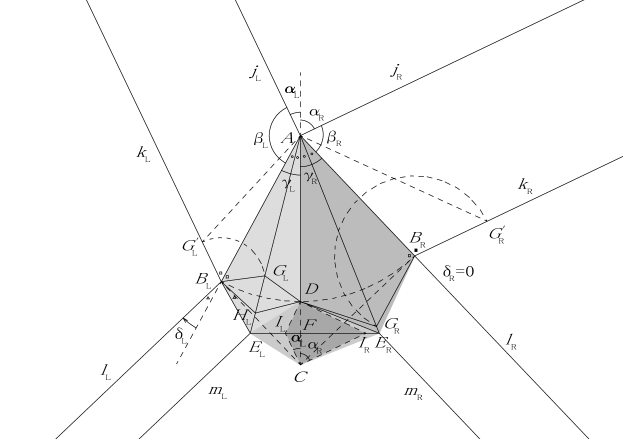
Throughout this paper, we will use for the vertices of the top face , and for those of the bottom face . In principle, from condition (d), we can successively extrude polyhedrons satisfying the above conditions (a)–(d) so that the top or a side face of each polyhedron includes the bottom face of the previous polyhedron. However, more layers of polyhedrons make the crease pattern much more complicated, and so we need to adjust widths and angles of the outgoing pleats appropiately. For , let to be the inner angle of at vertex , and , where the subscripts and stand for ‘left’ and ‘right’ respectively. We have
| (1.1) |
if and . For consistency, we consider as the definition of the angles on the left-hand side when or . Note that the above satisfy the following conditions:
-
(i)
, and , and
-
(ii)
for all .
Condition is necessary for each to form a non-flat solid angle. Condition enables us to develop without dividing any face of , preserving angles between edges of in and .
2. The conventional D gadgets developed by Natan
In this section we review the conventional D gadgets developed by Carlos Natan [8], which generalizes the cube gadget given in Figure 1.2. As a generalization of the cube gadget, let us consider a local model of an above-mentioned polyhedron as follows.
-
(A)
The object we want to extrude in the middel of the paper (which we suppose to be in the -plane ) with a D gadget is a part of a polyhedron such that its top face is bounded by two rays and starting from in , and its bottom face is bounded by two rays and with parallel to for , starting from in . Suppose the inner angle of the top face at (and so the inner angle of the bottom face at ) satisfies .
-
(B)
There are only simple pleats outside the extruded object.
Let for and . Then we develop the top and side faces on the paper as in Figure 2.1, where and are the mountain folds of the outgoing pleats, and and assemble to form ridge .

Lemma 2.2.
The height of the resulting extrusion is given by
where denotes the length of ridge , and is given by
| (2.1) |
Proof.
Since is scale-invariant, we may assume without loss of generality, in which case we have . For , let be the unit direction vector of ray , and . Also, let be the vector of the resulting extrusion. Then is obtained by a rotation of around for both . Thus we have
| (2.2) | ||||
| (2.3) | ||||
| (2.4) |
If we take to be the unit vector of the -axis, from we have
Letting and substituting into , we have
| (2.5) |
Then substituting into gives that
Hence we have
| (2.6) | ||||
| (2.7) | ||||
| (2.8) |
which completes the proof. ∎
Construction 2.3.
Consider a development as shown in Figure 2.1, for which we require the following conditions.
-
(i)
, and .
-
(ii)
.
-
(iii)
.
Then the crease pattern of Natan’s D gadget is constructed as follows, where all procedures are done for both .
-
(1)
Draw a perpendicular to through for both , letting be the intersection point.
-
(2)
Draw a perpendicular bisector to segment .
-
(3)
Determine a point on so that , and restrict to a ray starting from and going in the same direction as .
- (4)

| mountain folds | |
|---|---|
| valley folds |
Conditions and are the same as given in the end of Introduction, and these together imply as desired. Condition is necessary for the existence of the point inside angle in Figure 2.1. Note that for this gadget and move to and and form a triangular pyramid to support from inside the top and side faces.
We rewrite conditions – in terms of and as the following for the later convenience, which is clear by a straightforward calculation.
Lemma 2.6.
Conditions – of Construction 2.3 are equivalent to the following.
-
, and .
-
.
-
.
Remark 2.7.
Let be the intersection point of the extensions of and . Then is the circumcenter of , so that . If , then segment intersects (an extension of) before it intersects , where denotes the other side of . However, this is impossible. Indeed, if , then we have
and thus
which does not satisfy condition of Construction 2.3.
3. Constructing the crease patterns of the new D gadgets
To construct the crease pattern of our new D gadget, we begin with a development as in Figure 3.1, which is similar to Figure 2.1 but different in that we allow changes of angles of the outgoing pleats for . In our example, we are taking and for instruction.

Construction 3.2.
Consider a development as shown in Figure 3.1, for which we require the following conditions.
-
(i)
, and .
-
(ii)
.
-
(iii.a)
, where we take clockwise (resp. counterclockwise) direction as positive for (resp. ).
-
(iii.b)
for .
-
(iii.c)
, or equivalently, .
-
(iv)
for , where we exclude the simultaneous equalities , and are determined by
(3.1)
Validity of these conditions are discussed in Section 4. The first inequality of condition is derived from condition by Lemma 2.6, and thus abundant. However, we will leave condition as it is to compare the conditions needed in Constructions 2.3 and 3.2. The crease pattern of our new D gadget is constructed as follows, where all procedures are done for both .
-
(1)
Draw a perpendicular to through for both , letting be the intersection point.
-
(2)
Let be the intersection point of segment and the circular arc with center .
-
(3)
Let be the circumcenter of . Also, let be a ray parallel to and going in the same direction as , starting from . Thus is a perpendicular bisector to segment and bisects .
-
(4)
Let be the intersection point of segments and .
-
(5)
Determine a point on segment so that .
-
(6)
If , then determine a point on segment so that .
- (7)
The location of point in Construction 3.2, is derived from the foldability condition around point , which we will check in the next section.

| common | and | and | ||||
|---|---|---|---|---|---|---|
| creases | ||||||
| mountain | ||||||
| folds | ||||||
| valley | ||||||
| folds | ||||||
4. Constructibility and foldability of the crease pattern
In this section we discuss the validity of conditions – given in Construction 3.2 to ensure that the construction is possible. Also, we check the foldability of the resulting crease pattern.
Conditions and are the same as in Construction 2.3. For condition , we suppose the converse, i.e., . Then is greater than . Since no crease can be added inside , we cannot make the flat-foldablility hold around however we add creases inside . Condition is necessary for to be well-defined. Thanks to condition , we can find a point inside in Construction 3.2. If , then conditions – together are equivalent to condition of Construction 2.3. To consider condition , we derive .
Lemma 4.1.
The angles and dividing are determined by
In particular, we have
which incudes the case of .
Proof.
We may assume without loss of generality. For , let , and let be the unit direction vector of , which is normal to ray . Also, let . Then is written as
| (4.1) |
for some . Taking be the unit direction vector of the -axis, we have
| (4.2) | ||||||
Setting and substituting into gives that
Thus we have
| (4.3) | ||||
Substituting and into gives that
from which we deduce that
| (4.4) | ||||
Also, interchanging and in gives an expression for . The latter part of the lemma is trivial. ∎
Lemma 4.2.
Proof.
We may assume , and without loss of generality. Then must lie in the range , which gives that . Let with and let with be a point on segment such that bisects . If we set , then by condition and the direction vector of is given by rotating by angle , and so by rotating by angle . Hence never overlaps with and we have . ∎
Note that we have as in the above proof. We may also include in condition from the beginning.
Proposition 4.3.
For we have
and thus
Proof.
Let and . Since and are equilateral, so is , and it follows that and . Also, we see from that . Consequently we have , which completes the proof. ∎
In our construction, triangles and overlap on the left and the right face respectively, and thus in the crease pattern no crease is allowed to pass across these triangles. If , which is equivalent to
| (4.5) |
then passes across . Also, if and , which is equivalent to
| (4.6) |
then segment passes across . Hence we need the negation of and , that is,
| (4.7) |
Conversely, ensures that point lies on segment in Construction 3.2, and that lies on segment for in Construction 3.2, for . This is why we need condition of Construction 3.2. Note in particular that becomes
which is independent of .
Proposition 4.4.
If for both , then , i.e., the resulting extrusion is flat (of height zero), which does not satisfy condition of Construction 3.2.
Proof.
Define for by , so that we have . It is sufficient to prove that if , then . But from the definition of , we easily have
which completes the proof. ∎
Thus for a non-flat extrusion a special case for or for can occur only on either the left or the right side. This is why we exclude the case where for both in condition of Construction 3.2.
Now we shall check the foldability of the crease pattern given in Construction 3.2. For this purpose, we divide the crease pattern into two parts by polygonal chain . Then we can see easily that the upper part forms the top and the side faces with flat back sides, where and overlap with the side face for . Thus it remains to check that the lower part is flat-foldable to form the base of the extrusion. We show in Table 4.5 the adjacent vertices of or the rays starting from each vertex in the lower part, where denotes the other side of , and for vertex , we take into account both contributions from . Since vertices are interior points of the lower part, we can check the flat-foldability around them by Kawasaki’s theorem [7] (Murata-Kawasaki’s theorem may be more precise) that the crease pattern is (locally) flat-foldable if and only if the alternative sum of the angles around each vertex vanishes. Note that and around boundary point , and and around boundary point overlap with each other, so that around and , the alternative sums of the angles contained in the lower part must also vanish . For boundary point , and , which overlap with and respectively, form an angle . Thus around , the alternative sum of the angles contained in the lower part must be if we take the angle which contains as positive. In view of the above, the flat-foldability around each vertex in the lower part is checked as follows.
| and | and | |||
| — | ||||
Flat-foldability around . If , then the alternative sum of the angles around in the lower part is calculated as
If , then we have
Thus the alternative sum is given by
Flat-foldability around . As in the proof of Proposition 4.4, we define , so that . We divide as
and consider the contributions to the alternative sum of angles around from both sides separately. If , then we have
and thus
If , then we have
and thus
Consequently, in all cases the alternative sum is given by
which coincide with the angle formed by and as desired.
Flat-foldability around .
Suppose .
Then we have
which gives that
Next suppose . Then we have
which gives that
Flat-foldability around and . This is clear from the symmetry of and with respect to .
5. Interference coefficients and maximization of heights
In this section we consider a polyhedron as described in the end of Introduction, for which the bottom face and parameters (and so ) are all fixed for and . Also, we use the convention that and . For , let be a triangle with if . Then the maximal height of a polyhedron with these data is given by
where is given by by the sine theorem, and is given by . For , we denote by the polyhedron of height with the above data, and let be the corresponding vertices of the top face of . The length of ridge is given by .
If conditions – or conditions – hold for each and in Constructions 2.3 or 3.2 respectively, then a crease pattern of is constructible and locally foldable as shown in Section 4. However, it may not be globally foldable because interference of adjacent gadgets may occur. Let us see how D gadgets interfere with adjacent gadgets.
For conventional gadgets, interference with an adjacent conventional gadget occurs in the way that the two triangular pyramids supporting from inside collide. Thus in Figure 2.4 the lengths of of two adjacent gadgets which share the same edge are involved in the interference.
In the case of new D gadgets, interference occurs in a more complicated way. Consider the pleats formed by shadowed kites , which we call the ears of the gadget, and , which we call the thrusting part of the tongue (kite ) of the gadget, in Figure 5.1 may interfere with adjacent pleats, where is the intersection point of and a line through parallel to for . Observe that the tip of each ear swings to , and swings to with overlapping with . Then interference occurs in a bottom edge in the way that the tongue of the inner (first folded) pleat of one gadget collides with one of the ears of the outer (second folded) pleat of the other gadget. Thus in Figure 5.1 the length of of the inner gadget and that of of the outer gadget which share the same edge are involved in the interference.
To see if interference occurs or not, we introduce three kinds of interference coefficients for each vertex and two kinds of interference coefficients for each bottom edge with and . Before defining the coefficients, we calculate the following lengths.
Proposition 5.2.
In the resulting crease pattern Figure 3.3 in Construction 3.2, assume . Then we have
| (5.1) | ||||
where is given by , and and are given by
| (5.2) |
in terms of . Thus using and , we can express the lengths in in terms of , and not . In particular, if , then , and is simplified as
| (5.3) | ||||
Furthermore, if , then we have
| (5.4) | ||||
Proof.
To obtain an expression of , we use the sine theorem for . Then we have
so that
| (5.5) |
Recalling the proof of Lemma 4.1, we have
By the sine theorem for , we have
Thus we have
For the length of segment , we have
| (5.6) | ||||
| (5.7) | ||||
Then substituting and into gives that
The expression in for follows easily. For the last equality in , we set , so that . Then we have
This completes the proof of Proposition 5.2. ∎
Proposition 5.3.
Proof.
This is clear from and the expression for in for . ∎
Definition 5.4.
Consider a development of a polyhedron as described in the beginning of this section. Suppose conditions – of Construction 2.3 hold around all ridges . For a vertex in the development of with and , we define an interference coefficient of the conventional kind to be the ratio
of the length of segment to the height of the extrusion, where .
Also, for an edge of the bottom face (note that is located to the right of ), we define an interference coefficient of the conventional kind as
In particular, when we extrude a prism of , in which case we have and for all and , we will denote and by and respectively.
Definition 5.5.
Consider a development of a polyhedron as described in the beginning of this section. Suppose conditions – of Construction 3.2 hold around all ridges . In the resulting crease pattern in Construction 3.2, let be the points corresponding to ridge for . For a vertex in the development of , we define an interference coefficient of the inner pleat to be the ratio
Similarly, we define an interference coefficient of the outer pleat to be the ratio
Now we can define an interference coefficient of the new kind as
In particular, when we extrude a prism of , we will denote and by and respectively.
An interference coefficient in Definition 5.4 means the total length which the supporting pyramids of the conventional gadgets would occupy in edge of polyhedron , i.e., with . For a polyhedron with a general with , the total length in edge occupied by the conventional gadgets would be , and if , no interference of the conventional gadgets occurs in edge of , so that the gadgets are actually foldable. Conversely, , then the supporting pyramids of the conventional gadgets would collide in edge of , in which case Construction 2.3 fails.
Similarly, an interference coefficient in Definition 5.5 means the total length which the tongue of one new gadget and one of the ears of the other gadget would occupy in edge of polyhedron if we choose the inner and the outer pleats appropiately. Also, we see that if , then interference occurs in edge of if and only if .
Summarizing the above, we have the following theorems for the maximal heights of the extrusion with the conventional and the new D gadgets.
Theorem 5.6.
The maximum value of the height of polyhedron that can be extruded with the conventional D gadgets at one time is given by
Theorem 5.7.
The maximum value of the height of polyhedron that can be extruded with the new D gadgets at one time is given by
if we choose the order of the outgoing pleats appropiately.
Remark 5.8.
We defined interference coefficients as ratios to the height of the extrusion, which is a global variable in the extrusion. However, dealing with is a little troublesome because it does not appear explicitly in the development of the polyhedron we want to extrude and we have to compute each in terms of the angles around ridge . Instead of using , we can also use the length of ridge for any fixed in the definitions. This is particularly useful when all are the same, which occurs for example when and for all and . Then we obtain the maximal ridge length of the extrusion instead of the maximal height.
Remark 5.9.
Even if the ears and the tongue of a new gadget does not interfere with adjacent gadgets, there may be another kind of interference: the outermost point of an outgoing pleat may pass across the valley fold of the adjacent gadget. However, this interference is avoidable because we can fold back or sink with a crease parallel to the pleat through if and if , where is located closer to than if .
If , then we can fold back or sink the tongue of a new gadget with a crease through if and if , to reduce the inner interference coefficient . But this is not considered here from an aesthetic viewpoint.
6. Downward compatibility of the new gadgets
Theorem 6.1.
Proof.
We may assume . For the first inequality in , we calculate as
where the coefficient outside the parentheses in the last line is positive. Using the product-to-sum and sum-to-product formulas, we deform the terms in the parentheses in the last line as
because of and by Lemma 2.6, where equality holds for . This proves the first inequality in .
For the second inequality in , we have
| (6.3) | ||||
where the coefficient outside the parentheses in the last line is positive. Now we define and by
Then we have
so that and move in the following range:
| (6.4) |
The terms in the parentheses in the last line in become
where equality holds for , i.e., . This proves the second inequality in . ∎
Now we can state the downward compatibility theorem of the new D gadgets with the conventional ones as follows.
Theorem 6.2.
Any conventional D gadget can be replaced with our new D gadget with the same outgoing pleats without affecting any other conventional D gadget unless
| (6.5) |
holds. (It is impossible for both of the above inequalities to hold simultaneously.)
Proof.
Comparing the necessary conditions in Construction 2.3 with those in Construction 3.2 for , we see that an exceptional case where we cannot replace a conventional D gadget with our new one occurs if condition of Construction 3.2 fails, i.e., if
Suppose . Then using gives . If also holds, then we have , so that , which does not satisfy condition of both constructions.
Thus unless holds, we can replace a conventional gadget with our new one if we ignore other conventional gadgets. However, the interference coefficients of the new gadgets are always smaller than or equal to those of the conventional ones as shown in Theorem 6.1, the replacement does not affect any other existing conventional gadget.
Also, in both of Constructions 2.3 and 3.2 with , the location of point is the same. Since the widths of the resulting outgoing pleats are given by and in both constructions, the outgoing pleats are the same if we replace the conventional gadget with our new one. This completes the proof of Theorem 6.2. ∎
Corollary 6.3.
Let and be a convex polygon and angles for and . Suppose conditions – hold for all and . Then the maximum value of the height of that can be extruded by Construction 3.2 is always greater than or equal to the maximum value of that by Construction 2.3:
| (6.6) |
In particular, if for all and , and , then we can exclude the equality in , i.e., .
7. Numerical comparison of the efficiency for prisms
In this section we restrict ourselves to extruding a prism of a convex polygon . Thus we assume for all and , from which it follows that . Note that conditions – of Construction 2.3 and conditions – of Construction 3.2 hold automatically.
We already know from Corollary 6.3 that the new gadgets are more efficient than the conventional ones. To compare the efficiency numerically, we calculate the ratio of the maximal heights. For , we have the following formula for .
Theorem 7.1.
For any triangle, the maximal height of its prism that can be extruded with the conventional D gadgets at one time is the diameter of the incircle of the triangle. By Heron’s formula, for a triangle with side lengths a,b,c, the maximal height is given by
Proof.
Consider a triangle with . Let be the radius of the incircle of . Suppose the tangency points of the incircle divide sides into lengths of and , and , and and respectively, so that . Then we have
Thus the interference coefficients of the vertices are calculated as
and similarly . It follows that
Consequently, we have
| (7.1) |
which gives that . ∎
Similarly, we can calculate for as follows.
Theorem 7.2.
Let be a convex polygon. For , define to be the ray starting from and passing through respectively. Let be the radius of the circle tangent to side of and rays . Then we have
| (7.2) |
where is given by
| (7.3) |
Consequently we have
Proof.
Derivation of is almost the same as that of . Thus it remains to compute .
Suppose and let be the intersection point of and . Then the circle tangent to is the incircle of if , and the excircle tangent to if . By the sine theorem, we have
| (7.4) | ||||
| (7.5) |
Now we set by
Setting gives that
by a straightforward calculation. Then by the formulas for the inradius and exradii, we have
where
Thus in both cases is written as in . If , then is the distance between two rays and , and so
which is equal to the expression in for . ∎
Theorem 7.3.
Let be a convex polygon. For any side of , we have an inequality
In particular, if , i.e., if is a triangle, then for any we have
Proof.
Set and . Then it follows from for all that . The interference coefficients and are written as
Since the expression of is rather complicated, we instead consider an averaged coefficient defined as
Then we have an inequality
| (7.6) |
Let be a product set and for . Then since attains maximum on at , we have
| (7.7) |
where is a diagonal set, and the last equality holds because on . On the other hand, it follows clearly from that
| (7.8) |
Combining and gives that
Thus attains its supremum value as along . By the continuity of on , attains its supremum value as also on , where corresponds to .
Next we shall find the supremum value of if is a triangle. In this case we have for all , which is equivalent to . Setting as above, we have
so that
| (7.9) |
We see from that can be written in terms of and as
| (7.10) |
Now let be the domain of .
Lemma 7.4.
The domain is given by
| (7.11) |
Also, attains its supremum value as along the graph .
Proof.
For a fixed value of , moves in the range . Then we have with its derivative , which gives the following table.
Thus moves in the range . Considering also, we obtain .
For the supremum value of on , we consider the set bounding from below with respect to , because for a fixed value of , attains supremum for the infimum value of . By a straightforward calculation, is given by for and for . Thus we have
Hence attains its spremum value as along , which corresponds to . ∎
Note that the set bounding corresponds to the subset of , on which . Hence by a simular argument as above, attains supremum on as , which corresponds to . This completes the proof of Theorem 7.3. ∎
Corollary 7.5.
For any convex polygon , we have the following inequality for the maximal heights of the prisms of extruded with the conventional and the new gadgets:
In particular, if , i.e., if is a triangle, then we have
We show the D plots of and as fuctions of and . Observe that the D plot of has ‘ridges’ over the curves and in the -plane, where .
![[Uncaptioned image]](/html/1908.07342/assets/x10.png)
![[Uncaptioned image]](/html/1908.07342/assets/x11.png)
|
8. Repetition and division of D gadgets
Since the paper is flat outside the extruded polyhedron in both of Construcions 2.3 and 3.2, we can extrude another polyhedron so that its top or side face includes the bottom face of the previous polyhedron. In particular, we can repeat the same gadgets to make the extrusion higher as long as no interference occurs. Changing the viewpoint, we can divide a gadget into smaller gadgets which extrudes the same height in total. However, naive repetition of our new gadgets does not keep the back sides flat. In this section we present without proof a modification of our new gadgets for repetition which keeps the back sides flat. We shall deal with proportional division of a gadget into gadgets in the ratio with . Throught this section, we will suppose .
Construction 8.1.
Consider a development as shown in Figure 8.2, for which we require the following conditions.
-
(i)
, and .
-
(ii)
.
-
(iii)
.
-
(iv)
.
The crease pattern of the proportional division of our new D gadget into gadgets in the ratio from the bottom with is constructed as follows, where all procedures are done for both .
-
(1)
Draw a perpendicular to through for both , letting be the intersection point.
-
(2)
Divide segment (not ) into parts proportionally in the ratio , letting to be the divided points in order from the side of .
-
(3)
For , draw a ray parallel to , starting from and going in the same direction as , letting be the intersection point with .
-
(4)
For , let be the intersection point of a bisector of and a perpendicular bisector of , where we set and . Also, draw a ray parallel to , starting from and going in the same direction as . Thus we have parallel rays in order from the side of .
-
(5)
For , let be the intersection point of segments and .
-
(6)
For , draw a ray parallel to from to the side of . If intersects segment , then let be the intersection point. If not, then let be the intersection point with .
-
(7)
For , draw a ray starting from which is a reflection of across , where we set . If intersects segment , then let be the intersection point. If not, then it intersects at given in . Note that always exists, and for , exists if and only if exists.
-
(8)
For , draw a circle with center through and . If the circle intersects segment excluding endpoint , then let be the intersection point, and if and it intersects segment excluding endpoint , then let be the intersection point. Note that always exists. Also, as we will see in in Lemma 8.5, we have
which implies that exists if and only if exists.
-
(9)
For such that and in exist, draw a parallel line to segment through and a parallel line to segment through , letting be the common intersection point with segment .
-
(10)
For such that and in exist, draw a ray starting from which is a reflection of across . If the ray intersects , then is the intersection point. If not, then the ray intersects , letting be the intersection point. Also, draw a ray starting from which is a reflection of across . Then the ray passes through (resp. ) if exists (resp. does not exist).
-
(11)
For such that exist and do not, draw a line through which is a reflection of across , and a line through which is a reflection of across , letting be their common intersection point with segment . (If the two lines overlap , which happens only if and , then let .)
- (12)


| common | with such that | ||||
|---|---|---|---|---|---|
| creases | |||||
| mountain | |||||
| folds | |||||
| valley | |||||
| folds | |||||
Lemma 8.5.
Suppose and let , so that . Then we have
Also, we have
| (8.1) |
Proof.
Note that for , so that . Thus we see from that
as desired. The latter equation is then trivial. ∎
Remark 8.6.
In Construction 8.1, , if exists, then overlaps with because of . Also, if exists, then overlaps with by . Thus and overlap with as long as they exist. In other words, if exists, then overlaps with the innermost point of the tongue of the lowest gadget. Also, if exists, then overlaps with .
Proposition 8.7.
Suppose and let . Then points and given in Construction 8.1, exist if and only if
| (8.2) |
In particular, if (equal division) and , then and do not exist for .
Proof.
In the case of equal division,bwe show in Table 8.8 the number for various values of such that and for exist if and only if .
| none | ||||||||||||
|---|---|---|---|---|---|---|---|---|---|---|---|---|
Proposition 8.9.
Suppose and let as before. In Construction 8.1, points and given in exist if and only if
| (8.3) |
where we set . In particular, if , then and do not exist. Also, in the case of equal division, if , then and do not exist, and if , then and can exist only for .
Proof.
Suppose , so that . Let be the intersection point of and (possibly an extension of) . Then we can define the signed distance between and on by
| (8.4) |
where is the distance between and . We see that intersects segment , that is, exists, if and only if . Thus to prove the first assertion of the proposition, it is sufficient to prove the following result.
Lemma 8.10.
We have
| (8.5) | ||||
Proof.
As in the proof of Proposition 5.2, and move in the range given by . If we set also, then the left-hand side (LHS) of becomes
| LHS of | |||
which gives the equality in . Since is monotonically increasing with respect to both and in the range , we have
which gives the inequality in . ∎
It follows from Lemma 8.10 that is bounded from below as
| (8.6) |
If , then the RHS of vanishes, so that no and exist. The assertion of the proposition in the case of equal division is derived by setting and considering the condition that the RHS of is positive or zero for . This completes the proof of Proposition 8.9. ∎
In the case of equal division, we show in Table 8.11 the smallest number that makes the RHS of positive or zero for various values of . In other words, is the smallest number such that if and exist for , then satisfies for any .
| none | ||||||||||||
|---|---|---|---|---|---|---|---|---|---|---|---|---|
Remark 8.12.
Proposition 8.13.
Suppose in Construction 8.1. If and exist in , then given in and given in are identical points.
Proof.
Recall that is parallel to , while is contained in the reflection of across . Also recall that is contained in the reflection of . Since are parallel to each other, is parallel to . But it follows from that , and therefore both and are parallel to , which implies that . This completes the proof of Proposition 8.13. ∎
Thus from Propositions 8.7, 8.9 and 8.13, we obtain Table 8.14 which gives the assignment of mountain folds and valley folds in the case of in the resulting crease pattern in Construction 8.1.
| common | with such that | ||
|---|---|---|---|
| creases | |||
| mountain | |||
| folds | |||
| valley | |||
| folds | |||
Remark 8.15.
We may be able to assign another combination of of mountain folds and valley folds to the gadgets corresponding to the folding order of the gadgets. Note that in Construction 8.1, if we assign mountain folds and valley folds to the extrusion as in Table 8.4 or 8.14, then the layer of each gadget lies under that of the subsequent gadget. For , if points and do not exist, then we can exchange the order of the layer including in the -th gadget and the layer including or in the -th gadget. Correspondingly, creases change to valley folds and to a mountain fold from the assignment given in Table 8.4 or 8.14, while the assignment to the -th gadget is unchanged. This exchange of the layers makes the appearance of the ridge better, but the folding becomes a little more difficult in exchange.
Remark 8.16.
More or less surprisingly, upper gadgets do not interfere with adjacent gadgets in the sense that we can widen the outgoing pleats as we like at least theoretically, although we have to fold back their pleats appropriately so that they do not collide with adjacent pleats. Therefore, only the sizes of the lowest gadgets are restricted by their interference coefficients. As an example, we give in Figrure 8.17 two crease patterns of an extruded square prism five times as high as a cube with the same base, where we choose in the crease pattern on the left side, and on the right side. Observe that each of the double pleats of the upper gadgets in the crease pattern on the left side behaves as a single pleat with double thickness, and does not engage with other pleats in between its layers, while all layers of the pleats in the crease pattern on the right side are independent and engage with other pleats. As another example, we can extrude a square pyramid with a sharp end which cannot be extruded without repetition of new gadgets, whose crease pattern is given in Figure 8.18.


We end this section with the proportional division of a conventional gadget into gadgets. We use the same development as in the case of our new gadgets for comparison.
Construction 8.19.
Consider a development as shown in Figure 8.2, for which we require the following conditions.
-
(i)
, and .
-
(ii)
.
-
(iii)
.
The crease pattern of the proportional division of the conventional D gadget into gadgets in the ratio from the bottom is constructed as follows, where all procedures are done for both .
-
(1)
Draw a perpendicular to through for both , letting be the intersection point.
-
(2)
Divide segment into parts proportionally in the ratio , letting to be the divided points in order from the side of .
-
(3)
For , draw a ray parallel to , starting from and going in the same direction as , letting be the intersection point with .
-
(4)
For , draw a ray parallel to from to the side of , where we set . Also, draw a ray starting from which is a reflection of across , where we set and .
-
(5)
For , let be the intersection point of and .
-
(6)
Draw a perpendicular bisector of , letting be the intersection point with . Also, restrict to the ray starting from and going to the same direction as .
-
(7)
For , draw a perpendicular bisector of and a line through parallel to , letting be the intersection point of the two lines. Also, restrict to the ray starting from and going to the same direction as , which passes through .
- (8)

| common creases | with | |
|---|---|---|
| mountain folds | ||
| valley folds |
9. Remarks and further applications
In this section, we give some remarks on the constructions of the new D gadgets.
We also briefly review further applications of the new gadgets, some of which will be studied in more detail in a sequel to this paper.
Modification of the crease pattern.
Here consider the resulting crease pattern in Construction 3.2
and let us forget the crease patten on the side of , i.e., the other side of .
If , then we can duplicate the crease patten on the side of by reflection across , to obtain a new D gadget.
There is another way of constructing a new gadget.
Draw a circle with center through .
Draw a tangent line to the circle to the side of , letting to be the tangency point.
Choose a point on the circular arc excluding so that the region on the side of bounded
by the bisector of includes properly,
which is necessary for condition of Construction 3.2 to hold.
In other words, we choose on the circular arc excluding so that satisfies
.
Then is determined as a ray starting from and perpendicular to .
If we choose so that ,
then conditions – of Construction 3.2 hold, and thus we obtain another D gadget.
Insertion of a face.
Consider the resulting crease pattern in Construction 3.2.
Then we can insert a rectangular face of any width between ridge
as in Figure 9.1, where the newly added creases and are mountain folds.
When we insert a face between the ridge of the new cube gadget, we reproduce a gadget created by Natan in [8].
Using this operation, we can extrude a prism of a convex polygon with sides with new gadgets.
Also, we can repeat each new gadget to make the extrusion higher, although there may appear ‘horizontal streaks’ on inserted faces.
As an example,
we show in Figure 9.2 the crease pattern of an extruded hexagonal prism made by inserting three side faces to a triangular prism.


Negative D gadgets. In the developments in Figures 2.1 and 3.1 we have considered the face bounded by with inner angle as lying in for some , and the face bounded by as lying in . Alternatively, even if we suppose the faces bounded by and lie in and respectively, the development is the same. Thus we expect naturally that we can construct a ‘negative’ D gadget by modifying the resulting crease pattern in Construction 3.2. Here we shall give two constructions of negative D gadgets in the case , which differ in scope of application.
The first construction applies to cases where holds and holds for either or . We may assume . Let be the intersection point of segment and the ray starting from through . Also, let be the intersection point of ray and the ray starting from through . These points and exist because we have that
by the above conditions. Then the desired crease pattern is constructed as in Figure 9.3, and the assignment of mountain folds and valley folds is given in Table 9.4, where the subscript is taken for both . Note that in this construction, is rotated to the side of so that overlap with the left side face.

| mountain folds | |
|---|---|
| valley folds |
For the second construction, suppose either or holds. Let us consider the crease pattern in Figure 9.5, where we take so that segments and are parallel to segment . This is not the correct crease pattern because does not face the correct direction.

Let be the intersection point of a perpendicular to and a perpendicular to in the crease pattern. Also, let be the angle such that if rotates counterclockwise around by , then overlaps with an extension of . Then is calculated as
| (9.1) |
Let us define to be the projection of the resulting extrusion to the crease pattern in the bottom plane with . Then we have . Since in the bottom plane must be perpendicular to in the resulting extrusion, and also perpendicular to , we have to rotate couterclockwise around by .
However, the supremum angle (resp. ) by which we can rotate counterclockwise (resp. clockwise) is given by
| (9.2) |
where we exclude for which we have to fold back the pleat formed by and . Hence this construction is possible if , where and are given by and respectively, and the crease pattern is shown in Figure 9.6. Also, the assignment of mountain folds and valley folds is given in Table 9.7, where the subscript is taken for both .

| mountain folds | |
|---|---|
| valley folds |
Proposition 9.8.
Suppose either or holds. If , then the above second construction of negative D gadgets is always possible.
Proof.
We may assume . Also, we set for and . Note that we can choose any because is normal to any vector in the bottom plane.
First suppose . Then we have and . Also, it follows from Lemma 2.6 that
so that taking the tangents gives
Thus we see that and
| (9.3) |
Hence we calculate as
where we used in the last line. This gives .
Next suppose . Then it follows from Lemma 2.6 that
so that
which gives . Thus we calculate as
which gives .
Lastly, suppose (resp. ). Then we see from that (resp. ) as desired. This completes the proof of Proposition 9.8. ∎
Note that if , and , the first and the second constructions give the same result.
However, the second construction of negative D gadgets is not always possible for .
Indeed, if and (resp. ),
then we have (resp. ) and ,
and consequently .
Treatment of intersections of outgoing pleats. If , then the two pairs of the simple outgoing pleats and intersect. Although there are many ways of treating the outgoing pleats, let us describe a useful way of changing the outgoing pleats into one direction.
Let be the intersection point of and . Let and , and let (resp. ) be the intersection point of (resp. ) and its perpendicular through . Also, let be the intersection point of and . Without loss of generality, we may assume that and lies in the range by interchanging the left and the right sides if necessary. Then the -coordinate of satisfies one of the following: , , or . Examples of the crease patterns of the outgoing pleats in these cases are given as solid lines in Figure 9.9, where are the rays starting from respectively and perpendicular to , and we can choose any line parallel to and between and as a reference line by which (resp. ) is determined as a bisector of and (resp. and ). Also, the assignment of mountain folds and valley folds in all cases is commonly given in Table 9.10.

| mountain folds | |
| valley folds | (incl. ) (incl. ) |
Note that the sum of the widths of the outgoing pleats is given by in all cases, and the distance between and is given by . Note also that the ray starting from bisects and . Thus instead of using reflections across and , we can find and as the lines parallel to at a distance of , and then find and as their intersection points with and respectively.
One advantage of our treatment of outgoing pleats is that
we can shift the positions of intersecting pleats as in Figure 9.11,
which is useful when we make origami D tessellations.
As another advantage, the intersecting pleats tuck the altered pleats inside so as to prevent them from fluttering easily,
leaving only Y-shaped streaks on the front side.

Curved creases.
Since the extrusion with our new D gadgets has flat back sides, we can add new creases, which may be even curved, to the existing creases,
and deform the extruded object with the new creases.
For example, as described in Introduction, we can extrude a flat-foldable cube using the crease pattern shown in Figure 1.4.
As another example, we can make an extrusion with contours consisting of semicircles by adding sine curves to the crease pattern of a cuboid.
The crease pattern of the extrusion and the side views are shown in Figure 9.12,
where the dotted lines are unfolded when we deform the cuboid with the curved creases.

10. Conclusion
In the preceding sections, we presented the construction algorithms of our new D gadgets and their variantions in origami extrusions and described how to compute the interference coefficients to maximize the efficiency when extruding a polyhedron with the D gadgets. Using the interference coefficients, we proved the downward compatibility theorem of the new D gadgets with the conventional ones, and particularly we compared numerically the maximal height of the prism of a given convex polygon which can be extruded with the new D gadgets with that which can be extruded with the conventional ones.
Since for a given polyhedron there are many ways of designing the crease pattern of its extrusion, selecting the optimal folding method and controlling the angles of the outgoing pleats will be of some interest in computer-aided design. The new D gadgets are theoretically always more efficient than the conventional ones when both kinds of gadgets are applicable, but the conventional gadgets are practically more suited when is very small because the new gadgets need finer creases and are more difficult to fold. Also, if , then we can only apply the conventional D gadgets. On the other hand, when is very small, the new gadgets may be the only practical solution because of the efficiency. Thus we should use the two kinds of D gadgets selectively in accordance with the situation, using the compatibility.
Althouth our new D gadgets enable us to extrude a polyhedron which was impossible or very difficult to extrude with the conventional methods, our methods are still very limited to extrude a general polyhedron such that many edges assemble at its vertex. Studying the examples of a regular octahedron and a regular icosahedron extruded by Natan [8] and the author [6] respectively may be a key to overcoming this difficulty. There are still a lot to be studied including the above, and we expect further developments in future research on the basis of our results in this paper.
References
- [1] Nadia M. Benbernou, Erik D. Demaine, Martin L. Demaine, and Aviv Ovadya, Universal hinge petterns for folding orthogonal shapes, : Fifth International Meeting of Origami Science, Mathematics, and Education (Ed. P. Wang-Iverson et al.), 405–419, A K Peters/CRC Press, 2011.
- [2] Herng Yi Cheng, Extruding towers by serially grafting prismoids, : I: Mathematics (Ed. K. Miura et al.), 275–292, American Mathematical Society, 2016.
- [3] Erik D. Demaine, Martin L. Demaine, and Jason S. Ku, Folding any orthogonal maze, : Fifth International Meeting of Origami Science, Mathematics, and Education (Ed. P. Wang-Iverson et al.), 449–454, A K Peters/CRC Press, 2011.
- [4] Erik D. Demaine, Martin L. Demaine, and Joseph S. B. Mitchell, Folding flat sihoulettes and wrapping polyhedral packages: New results in computational origami, Comput. Geom. Theory Appl. 16(1) (2000), 3–21.
- [5] Erik D. Demaine and Tomohiro Tachi, Origamizer: A practical algorithm for folding any polyhedron, manuscript, 2010.
-
[6]
Mamoru Doi, D origami, Mamoru Doi’s photostream at flickr.com, https://www.flickr.com/photos/69402128@N03/
albums/72157628111553826/, 2011. - [7] Toshikazu Kawasaki, On the Relation Between Mountain-Creases and Valley-Creases of a Flat Origami, Proceedings of the 1st International Meeting on Origami Science and Technology (Ed. H. Huzita), Ferrara, Italy, 229–237, 1989.
- [8] Carlos Natan Lopéz Nazario, Origami D tessellations, Carlos Natan Lopéz Nazario’s photostream at flickr.com, http://www.flickr.com/photos/origamiz/sets/72157606559615966/, 2010.