Third method for generation of spectral holes
in
chiral sculptured thin films
Fei Wang111Corresponding Author. Fax: +1 814 863 7967; e–mail: fuw101@psu.edu and Akhlesh Lakhtakia222E–mail: akhlesh@psu.edu
CATMAS — Computational and Theoretical Materials Sciences Group
Department of Engineering Science and Mechanics
Pennsylvania State University, University Park, PA
16802–6812, USA
Abstract: The introduction of either a central layer defect or a central twist defect in a periodic structurally chiral material generates circular–polarization–sensitive spectral holes in the remittance spectrums for normally incident plane waves. We propose and theoretically establish here the third method to generate such spectral holes using two–section chiral sculptured thin films (STFs). Both sections of the proposed device have the same periodicity and handedness, but their dielectric properties are different and related in a specific way. The concept of pseudoisotropy is highly relevant for the production of the proposed device.
Keywords: Cholesteric liquid crystals; Layer defects; Pseudoisotropy; Sculptured thin films; Structural chirality; Spectral holes; Twist defects
1 Introduction
The generation of an intra–band spectral hole was first demonstrated by inserting a phase defect in the center of a scalar Bragg grating [1]. The scalar Bragg grating, without the central phase defect, has a spectral regime of high reflectance for normally incident plane waves. This regime is called the Bragg regime. When the central phase defect is inserted, the Bragg regime is punctured by a much narrower high–transmittance regime. This second regime is called a spectral (reflection) hole and is widely employed in laser optics [2] as well as in optical–fiber communication [3, 4].
As a scalar Bragg grating is insensitive to the polarization state of the incident plane wave, the incorporation of a central phase defect gives rise to a reflection hole regardless of the polarization state. In order to generate circular–polarization–sensitive reflection holes, periodic structurally chiral materials — exemplified by chiral sculptured thin films (STFs) and cholesteric liquid crystals (CLCs) [5]–[9] — are used in lieu of scalar Bragg gratings. In general, these materials discriminate between incident plane waves of different circular polarization states in the Bragg regime. Periodic structurally chiral materials and circularly polarized plane waves possess handedness. In the Bragg regime, the reflectance is very high for a co–handed normally incident plane wave, but not for the cross–handed one — leading to the term circular Bragg phenomenon. As the high reflectance in the Bragg regime is co–handed only, so is the reflection hole in the Bragg regime generated by the insertion of a central phase defect in the periodic structurally chiral material.
Theoretical analysis has recently engendered another spectral hole — i.e., a cross–handed transmission hole — in a periodic structurally chiral material by the introduction of a central phase defect [10]–[12]. The thickness of the periodic structurally chiral material is crucial to the exhibition of the two types of spectral holes. When the thickness is relatively small, the co–handed reflection hole occurs. As the thickness increases, the co–handed reflection hole diminishes to vanish eventually and it is gradually replaced by the cross–handed transmission hole. The bandwidth of the second type of spectral holes is a tiny fraction of that of the first type. However, even modest dissipation can be deleterious to the second type of spectral holes [11]. Needless to add, the second type cannot be generated using scalar Bragg gratings.
The central phase defects investigated thus far are of two types:
-
(i)
Layer defect: A homogeneous layer, whether isotropic [5, 6] or anisotropic [13], is inserted in the center of the grating. The thickness of the homogeneous layer determines the center wavelength of the spectral hole, with a quarter–wave layer positioning the spectral hole quite accurately in the center of the Bragg regime [14].
-
(ii)
Twist defect: One half of the periodic structurally chiral material is rotated about the thickness axis with respect to the other half by a certain angle [8, 10, 11, 15] The amount of rotation determines the center–wavelength of the spectral hole, with a –twist positioning the spectral hole in the center of the Bragg regime.
Combinations of the two types of phase defects are likely to offer superior performance than either alone [12].
We propose here a third method to generate both types of spectral holes in periodic structurally chiral materials. This method can be implemented with chiral STFs but not with CLCs. It is based on the selection of a two–section chiral STF with the two sections having different dielectric properties but the same periodicity and the same handedness. The relevant boundary value problem for normally incident plane waves is briefly described in Section 2, while the proposed method and its possible implementation are examined in Section 3. The concept of pseudoisotropy is highy relevant to the implementation of our proposal [16, 17].
2 Theory
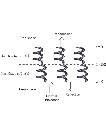
Suppose the region is occupied by a two–section chiral STF, while the half–spaces and are vacuous, as shown in Figure 1. The relative permittivity dyadic of the chiral STF is stated as follows:
| (1) |
Here and hereafter, , (), are the reference relative permittivity scalars of the th section; are the unit cartesian vectors with parallel to the axis of nonhomogeneity of the chiral STF; the rotational dyadic
| (2) |
where , is the structural period, and the parameter for structural right–handedness and for structural left–handedness; and the tilt dyadic
| (3) |
represents the locally aciculate morphology of the STF with as the tilt angle. The scalars , (), are implicitly dependent on the free–space wavelength , and for chiral STFs. The ratio is set as a positive integer. For convenience, we define
| (4) |
Parenthetically, the relative permittivity dyadic of CLCs can be described by (1) as well, but with the restrictions and .
The two–section chiral STF is axially excited by a normally incident, circularly polarized plane wave from the half–space . The procedure to obtain the planewave reflectances and transmittances is devised from the solution of a boundary value problem detailed elsewhere [14, 18]. Let us content ourselves here by stating that algebraic matrix equation [5]
| (5) |
eventually emerges, where the column–4 vectors and contain the – and the – components of the electromagnetic field phasors at the entry and the exit pupils, respectively. The 4 matrix
| (6) |
relating and is computed using the matrixes
| (7) |
where is the intrinsic impedance of free space. The derivation of (6) does not account for the possible excitation of Voigt waves [19]; but that possibility is remote, and can occur only for highly dissipative chiral STFs [20].
3 Proposed Method
The planewave remittances (i.e., reflectances and transmittances) can be easily computed after solving (5). But our interest was in finding relationships between and , () for the generation of the two types of spectral holes.
We determined that the relationships
| (8) |
lead to the identity
| (9) |
Therefore, satisfaction of the conditions (8) implies that (6) converts to
| (10) |
where
| (11) |
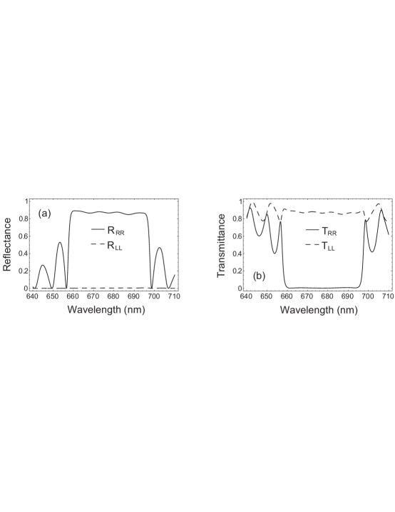
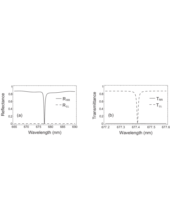
The matrix of (10) is identical to that formulated for an axially excited chiral STF with a central –twist defect [8]. Therefore, the two–section chiral STF satisfying the conditions (8) should resemble a chiral STF with a central –twist defect in terms of the response to normally incident plane waves.333It is worth mentioning that, although the responses to normally incident plane waves are the same for the two–section chiral STF satisfying (8) and for a chiral STF with a central –twist defect, the –directed components of the electric fields in the region are different in general. Therefore, the two types of devices, although functioning equivalently in terms of the generation of spectral holes, are not identical electromagnetically. Accordingly, both types of spectral holes must emerge in the optical remittance spectrums of a two–section chiral STF obeying (8) as the thickness changes; see the spectrums of the co–polarized remittances in Figures 2 and 3 for an illustrative example. The bandwidths of the spectral holes are so small that dispersion of the constitutive scalars can be ignored in most instances.
The theoretical underpinnings of the proposed method having been thus established, let us turn our attention to the feasibility of fabricating the described device. Chiral STFs are fabricated by directional physical vapor deposition, whereby the vapor of an inorganic material is directed towards a substrate at an angle to the substrate plane [14, 23]. Optical characterization experiments on (nonchiral) columnar thin films [22] indicate that and are all monotonically increasing functions of . From the collected data, it has been shown that there exists a value (called the pseudoisotropic value) of such that [24]. Furthermore, for ; thus, the local birefringence changes sign as the pseudoisotropic value of is crossed. The value of is dependent on the type of evaporant [22] and most likely on the deposition conditions as well [25].
It follows that the two sections of the proposed device must be deposited with vapors of different materials (or combinations of materials). For example, suppose , and therefore . Then the section labeled must be deposited at a low enough value of such that , whereas the section labeled must be deposited at a high enough value of such that . Furthermore, the two materials should be properly selected such that .
Could the proposed device be made by depositing vapor of a single material? Based on the limited experimental data reported for columnar thin films [22], the answer is in the negative. Since the sum increases monotonically with , (8) cannot be fulfilled with just one material being deposited first with vapor directed at angle and then at .
Could a pair of CLCs be made to satisfy the conditions (8)? The answer to this question is in the negative as well, because (i) for CLCs and (ii) the rodlike shapes of molecules [26] impose the restriction . In other words, neither a single–material, two–section chiral STF nor a combination of two CLCs can be utilized to implement the proposed third method for the generation of the two types of spectral holes. However, with the choice of a single–material chiral STF for one section and a CLC for the second section, it could, in principle, be possible to satisfy (8).
To conclude, we have theoretically established here the third
method (in addition to the ones calling for the insertion of layer
and twist defects) to generate circular–polarization–sensitive
spectral holes using STF technology. The proposed device is
optically similar to
a chiral STF with a central
–twist defect. Finally, we have assessed the technological
feasibility of implementing the proposed method.
Acknowledgment This work was supported in part by a US National Science Foundation grant. FW thanks Prof. J.A. Todd (Penn State) for continued support.
References
- [1] H. A. Haus, C. V. Shank, IEEE J. Quantum Electron. 12 (1976) 352.
- [2] G. P. Agrawal, N. K. Dutta, Semiconductor Lasers, Van Nostrand Reinhold, New York, 1993 (Chap. 7).
- [3] G. P. Agrawal, S. Radic, IEEE Photon. Technol. Lett. 6 (1994) 995.
- [4] F. Bakhti, P. Sansonetti, J. Lightwave Technol. 15 (1997) 1433.
- [5] A. Lakhtakia, M. McCall, Opt. Commun. 168 (1999) 457.
- [6] I. J. Hodgkinson, Q. h. Wu, A. Lakhtakia, M. W. McCall, Opt. Commun. 177 (2000) 79.
- [7] Y.–C. Yang, C.–S. Kee, J.–E. Kim, H. Y. Park, J.–C. Lee, Y.–J. Jeon, Phys. Rev. B 60 (1999) 6852.
- [8] I. J. Hodgkinson, Q. H. Wu, K. E. Thorn, A. Lakhtakia, M. W. McCall, Opt. Commun. 184 (2000) 57.
- [9] V. I. Kopp, A. Z. Genack, U.S. Patent 6 396 859, 2002.
- [10] V. I. Kopp, A. Z. Genack, Phys. Rev. Lett. 89 (2002) 033901.
- [11] F. Wang, A. Lakhtakia, Opt. Commun. 215 (2003) 79.
- [12] I. J. Hodgkinson, Q. h. Wu, L. De Silva, M. Arnold, M. W. McCall, A. Lakhtakia, Phys. Rev. Lett. 91 (2003) 223903.
- [13] A. Lakhtakia, V. C. Venugopal, M. W. McCall, Opt. Commun. 177 (2003) 57.
- [14] A. Lakhtakia, R. Messier, Sculptured Thin Films: Nanoengineered Morphology and Optics, SPIE Press, Bellingham, WA, USA, 2005 (Chap. 10), to be published in Jan. 2005.
- [15] J. Schmidtke, W. Stille, Eur. Phys. J. E 12 (2003) 553.
- [16] I. Abdulhalim, Europhys. Lett. 48 (1999) 177.
- [17] A. Lakhtakia, W. S. Weiglhofer, J. Opt. A: Pure Appl. Opt. 2 (2000) 107.
- [18] V. C. Venugopal, A. Lakhtakia, Proc. R. Soc. Lond. A 454 (1998) 1535.
- [19] A. Lakhtakia, Opt. Commun. 157 (1998) 193.
- [20] A. Lakhtakia, J. Phys. D: Appl. Phys. 31 (1998) 235.
- [21] I. J. Hodgkinson, Q. h. Wu, M. Arnold, M. W. McCall, A. Lakhtakia, Opt. Commun. 210 (2002) 201.
- [22] I. J. Hodgkinson, Q. H. Wu, J. Hazel, Appl. Opt. 37 (1998) 2653.
- [23] R. Messier, A. Lakhtakia, Mater. Res. Innov. 2 (1999) 217.
- [24] A. Lakhtakia, Microw. Opt. Technol. Lett. 34 (2002) 367.
- [25] R. Messier, personal communication to A. Lakhtakia (2004).
- [26] P. G. de Gennes, J. Prost, The Physics of Liquid Crystals, Clarendon Press, Oxford, UK, 1993 (Chap. 4).