The interplay of electron-photon and cavity-environment coupling
on the
electron transport through a quantum dot system
Abstract
We theoretically investigate the characteristics of the electron transport through a two-dimensional a quantum dot system in the -plane coupled to a photon cavity and a photon reservoir, the environment. The electron-photon coupling, , and the cavity-reservoir coupling, , are tuned to study the system in the weak, , and the strong coupling regime, . An enhancement of current is both seen with increasing and in the weak coupling regime for both - and -polarization of the photon field. This is a direct consequence of the Purcell effect. The current enhancement is due to the contribution of the photon replica states to the electron transport in which intraband transitions play an important role. The properties of the electron transport are drastically changed in the strong coupling regime with an -polarized photon field in which the current is suppressed with increasing , but it is still increasing with . This behavior of the current is related to the population of purely electronic states and depopulation of photon replica states.
I Introduction
The spontaneous emission of a quantum dots (QD) coupled to photon sources has been exploited to study the optical properties of QD materials Decker et al. (2013); Rahmani and Bryant . Controlling the spontaneous emission is a nontrivial task and is considered to be at the heart of quantum optics Lodahl et al. (2004) and is essential for diverse applications such as single-photon sources for quantum information Kuhn et al. (2002); De Greve et al. (2012); Frisk Kockum et al. (2019), optical energy harvesting Grätzel (2001), and light-emitting diodes Noda et al. (2001). The enhancement of a quantum system’s spontaneous emission rate by its environment is called the Purcell effect Purcell et al. (1946) and has been studied by many researchers in different systems Kiraz et al. (2003); Landi et al. (2018). A strong Purcell enhancement is observed for quantum dots coupled to periodic metal-dielectric multi-layers that can benefit various nanophotonic applications Li et al. (2019). The emission intensity of spin-dependent exciton states can be enhanced at a resonance due to the Purcell effect Ren et al. (2012). In addition, the enhancement of the Purcell effect has been achieved by controlling the effective coupling with the micro-cavity Wilk et al. (2007); Press et al. (2007).
The cavity quantum electrodynamics (QED) was proposed by Weisskopf and Wigner to control the spontaneous emission rate of a single photon source Weisskopf and Wigner (1930); Pelton (2015). In cavity QED, the spontaneous emission rate is characterized by the mode density of the quantized photon field which is known as the Purcell effect in the context of cavity QED. Recently, a QD system was used to enhance the spontaneous emission by a single photon nanocavity coupled to the environment Wei et al. (2019), where the coherency of the single photon source should be maintained Aspuru-Guzik and Walther (2012); Cialdi et al. (2017).
High Purcell factor indicating a significant enhancement of an emission rate needs a cavity confining light of small dimensions or storing light for a long time Muljarov and Langbein (2016). This requires a high Q factor or a cavity with a nanoscale volume. Generally, parameters should be carefully considered for obtaining a high Purcell factor, such as the electron-photon coupling strength, , Cottet et al. (2015), and the coupling strength of the cavity-photon field to the environment, Dewhurst et al. (2010); del Valle and Laussy (2011). A system is said to be in the weak coupling regime if the electron-photon coupling strength is smaller than or equal to the coupling strength of the photon cavity to the environment, , while in the strong coupling regime the condition should be Snijders et al. (2018). In the weak coupling regime, the efficiency of a single photon generation can be significantly enlarged, forming high-quality single photon generation by photon blockade possible with current state-of-the-art samples Müller et al. (2015). Furthermore, the cavity-dot system can be made in a single step using a far-field optical lithography process monitoring a nonlinear optical transition of the QD system in which the observation of strong Purcell effect is evidenced Dousse et al. (2008). In contrast to the weak coupling regime, the Rabi oscillations in a QD exposed to a quantized photon field in the strong coupling regime lead to current peaks in connection with different types of photoluminescence Leng et al. (2018); Cirio et al. (2016); Gudmundsson et al. (2018a); Eichler et al. (2012); Lang et al. (2011). In addition, photon-assisted tunneling has been observed in a two-level system with Rabi-effect Faraon et al. (2008) and also studied in a many level QD Gudmundsson et al. (2015). Therefore, the strong coupling regime has been proposed for industrial technology Sillanpää et al. (2007); Majer et al. (2007); Wu et al. (2019).
The study of current transport in a QD-cavity is still lacking information Hanschke et al. (2018); Lin and He (2015) where the signs of Purcell effect appear. In this work, we consider a QD system coupled to a cavity and the photon reservoir in both the weak and the strong coupling regimes where the photon field is fully quantized Giannelli et al. (2018); Kreinberg et al. (2018). We compare the transport properties between these two regimes, where this comparison has not been demonstrated in our previous publications Abdullah et al. (2014); Gudmundsson et al. (2019); Abdullah et al. (2015); Gudmundsson et al. (2012); Abdullah et al. (2017). We assume a two-dimensional electron system consisting of a QD embedded in a short quantum wire and coupled to two electron reservoirs Zhang et al. (2016). The transport properties of the QD system in the steady-state is investigated under the influence of a quantized photon field in a cavity using a Markovian quantum master equation Jonsson et al. (2017).
II Theoretical formalism
We consider a multi-level QD embedded in the center of a quantum wire in -plane where the wire-dot system is hard-wall and parabolic confined in the - and -direction, respectively Gudmundsson et al. (2012). The diameter of the QD is nm and the length of the quantum wire is nm. The QD system is attached to two electron reservoirs, leads, from both ends in the -direction. The total system, the QD and the leads, are microstructured in a GaAs heterostructure, and exposed to a perpendicular magnetic field in the -direction, . The QD system is placed in a photon cavity that is coupled to a photon reservoir. The photon field is linearly polarized in the 3D rectangular cavity Abdullah et al. (2017, 2016). We let the photons in the cavity to be polarized in either - or -direction, of which the latter is the direction of transport through the system. The schematic diagram and the potential of the QD system coupled to the photon cavity can be seen in Abdullah et al. (2019a).
The Hamiltonian of the QD system coupled to the photon cavity is Jonsson et al. (2017); Gudmundsson et al. (2016); Arnold et al. (2015); Gudmundsson et al. (2018b)
| (1) |
where the energy of a single-electron (SE) state and the gate voltage are presented as , and , respectively. The Coulomb matrix elements in the SE state basis are
| (2) | |||||
with being the SE wavefunctions, the Coulomb interaction potential , and () being the electron creation (annihilation) operator of the QD system Gudmundsson et al. (2013). To treat the Coulomb interacting many-electron (ME) Hamiltonian in the QD system, an “exact numerical diagonalization” method is utilized Yannouleas and Landman (2007).
In the second line of Eq. (1): indicates the Zeeman Hamiltonian where refers to the effective Landé g-factor, is the Bohr magneton, displays the weak external magnetic field, and is a Pauli matrix. , introduces the photon field in the cavity where indicates the photon energy and and are the photon creation and annihilation operators, respectively.
The interaction between the electrons in the QD system and the photons in the cavity can be defined by the paramagnetic (last term of the second line of Eq. (1) ) and the diamagnetic Hamiltonian (third line of Eq. (1)) with the dimensionless electron-photon coupling matrix, and the photon number operator Gudmundsson et al. (2012). The electron-photon coupling strength can be represented by and is the electron effective confinement frequency.
To investigate the evolution of the electrons in the QD system in the steady state regime, we use a Markovian master equation where the projection formalism is used based on the density operator Zwanzig (1960); Nakajima (1958). We are interested in the state of the central system, QD system after the coupling to the leads, the reduced density operator of the central system can be written as
| (3) |
where is the density operator of the total system. Here, the trace over the Fock space of the left (L) and the right (R) leads is taken into account Gudmundsson et al. (2018b); Lax (1963); Gardiner and Collett (1985); Beaudoin et al. (2011),
The current from the left lead into the QD-system, , and the current from it into the right lead, , can be introduced as
| (4) |
where is the charge operator of the wire-QD system with the electron creation (annihilation) operator of the wire-QD system, respectively. The operators represent the “dissipation” processes caused by both leads Gudmundsson et al. (2019); Jonsson et al. (2017).
III Results
We present the characteristics of the electron transport through the QD system in this section. We assume the system to be in a weak external perpendicular magnetic field, T, to lift the spin degeneracy, but at the same time we want to avoid the effects of a strong Lorentz force on electron transport. The chemical potential of the left and the right leads are and meV, respectively, and the temperature of the leads is fixed at K. The gate voltage is eV that shifts the energy states of the QD system with respect to the chemical potential of the leads. Furthermore, the photon energy is assumed to be meV. Under this condition the system is said to be in the off-resonant regime with respect to the lowest in energy electron states because the photon energy is smaller than their energy spacing. The mean photon number in the photon reservoir is assumed to be .
III.1 Weak coupling regime,
In this section, we consider the electron-photon coupling strength, , to be smaller than or comparable to the selected range of the cavity-environment coupling strength, . The energy spectrum of the QD-cavity system as a function of is shown in Fig. 1.
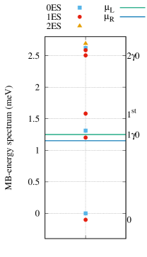
The cavity-environment coupling parameter, , is included in the Markovian master equation that is used to investigate the electron motion through the QD system here Gudmundsson et al. (2019). The energy spectrum of the closed system displayed in Fig. 1 is independent of . The green and the blue horizontal lines are the chemical potential of the left and the right leads, respectively. 0 indicates the one-electron ground-state, labels the one-electron first-excited state, and 10 and 20 are the first and the second photon replicas of the one-electron ground-state, respectively. We should point out that each mentioned state includes both Zeeman spin components, spin-down and spin-up states, which are separated by the small Zeeman energy due to the presence of small external magnetic field.
Since the photon energy is smaller than the spacing between the lowest energy states of the QD system, , the one photon replica of the ground state, 10, is located between 0 and , the system is in an off-resonant regime. Furthermore, the gate voltage, meV, moves up the 10 into the bias window, . As expected, the 10 stays in the bias window when the cavity-environment coupling, , is varied, because changing does not influence the physical characteristics of the closed QD system. We should remember that the energy spectrum for the -polarized photon field is almost the same as for the -polarizatized case for the low coupling regime, , (not shown).
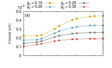
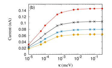
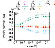
The transport properties of the QD system are presented in Fig. 2 in which the steady-state current as a function of the cavity-environment coupling is plotted for an - (a) and -polarized (b) photon field. The current increases with in the selected range of the cavity-environment coupling strength.
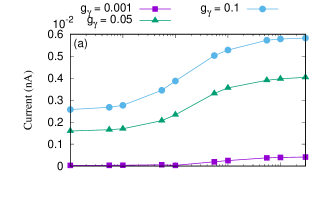
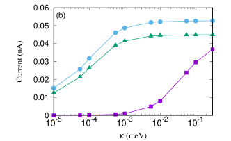
It can be clearly seen that the current in the -polarized photon field is ten times larger than for the -polarization for and meV. This is due to the fact that the states of the QD system are more polarizable in the -direction and the photon replica states are actively contributing to the current transport compared to the -polarization which will be shown later. But for the very low coupling when meV, the current is almost the same for both photon polarizations since the photon field, and in turn the photon replica states, do not play an important role in the current transport for such a low .
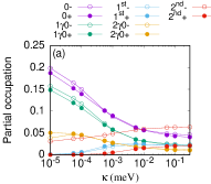
The most interesting point here is that the current is increased with the cavity-environment coupling which is a direct consequence of the Purcell effect. To better understand it the partial occupation (a,b) and the partial current (c,d) of the ten lowest one-electron states are plotted for (top panel) and meV (lower panel) in Fig. 3 where the minus and the plus signs indicate the Zeeman spin-down and spin-up states, respectively.
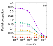
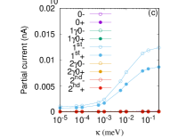
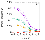
Let’s first take a look the low coupling strength of the electron-photon, meV (Fig. 3 (top panel). Increasing , the occupation of all selected states is decreased as is shown in Fig. 3(a). It demonstrates that the lifetimes of the state in the bias window and the corresponding photon replica states get shorter and in turn less charge resides in these states. The corresponding current transport presented in Fig. 3(c) demonstrates that only the first-excited state located just above the bias window, (blue circles), is active in the current transport. It can be verified that the photon replica states do not participate to the current transport at the low electron-photon coupling strength, meV, even though 0 is located in the bias window. The reason for the current enhancement through the state is the depopulation of the photon replicas by the relatively large .
Increasing the electron-photon coupling strength to meV as shown in Fig. 3(b) and (d), the occupation of the first- (blue circles) and the second-excited (red circles) states is slightly increased with while the occupation of the ground-state and its photon replicas decreases as is demonstrated in Fig. 3(b). This indicates that the lifetimes of the and the get relatively longer than the lifetimes of the photon replica of the ground-state in the bias window.
The states with short lifetime, and the ground-state, become active in the current transport at higher electron-photon coupling strength, meV, as it is shown in Fig. 3(d). The reason for the activation the photon replica states is related to the intraband transition between these states. The current is going from the left lead to the right lead via the one-photon replica state located in the bias window while an inversion of the current transport is seen via the and the which have a relatively longer lifetime than the photon replicas and are located outside the bias window. This can be understood as the following: The charge is more accumulated in the and the and they are closer to the Fermi energy of the left lead leading to a current being transferred from these two states to the left lead appearing as a negative current. The participation of the photon replica states in the current transport at the higher electron-photon coupling strength meV enhances the total current compared to the case of the low electron-photon coupling strength meV. Therefore, the total current is enhanced with as is shown in Fig. 2.
III.2 Strong coupling regime,
In this section, we consider the case when the electron-photon coupling strength is stronger than the selected range of the cavity-environment coupling strength, , i.e. the strong coupling regime.
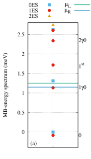
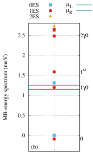
Figure 4 displays the MB-energy spectrum of the QD system as a function of for - (a) and -polarization (b) of the photon field when meV which is higher than the selected range of cavity-environment coupling strength, . In general, tuning the electron-photon coupling strength in the case of the -polarization shifts the energy of the states and could lead to resonant states Abdullah et al. (2019b). Comparing to the low electron-photon coupling strength, meV shown in Fig. 1, the 10 moves out of the bias window and the is shifted up for the -polarization (Fig. 4(a)) while these changes in the -polarization are not observed (Fig. 4(b)). If we further tune to higher values, one notes a resonance between 1st and 20 in the -direction (not shown). The resonant states will have major roles in the electron transport in the system. As we mentioned before, tuning does not affect the energy states of the closed QD system.
Figure 5 displays the current versus in the - (a) and -polarization (b) for different values of the electron-photon coupling strength (golden diamonds), (blue star), (black cross), and meV (red), which are all greater than the selected range of . The characteristics of the current in the system is drastically changed for the -polarization in the strong coupling regime. The current is suppressed with increasing for the -polarization (Fig. 5(a)) throughout all values of while it is enhanced in the -polarization (Fig. 5(b)). It indicates that the photon field with -polarization is dominant at high or strong electron-photon coupling strength and the cavity-environment coupling effect is diminished. In addition, the current increases with in both directions of the photon polarization which displays a manifestation of the Purcell effect in the system, even when . We should keep in mind that the current was enhanced with for both directions of the photon polarization at the low coupling regime shown in Fig. 2.
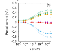
The current suppression is related to a shift of the energy of the states that occurs at the strong coupling regime in the -polarized photon field presented in Fig. 4(a). The energy shift affects the characteristics of the electron transport through the individual states of the QD system. To see these effects we present the partial occupation (a) and the partial current (b) for the -polarization in Fig. 6.
We start with the -polarized photon field with meV (Fig. 6(a)), in which the occupation of the pure electronic states, 1st (blue) and 2nd (red), is much enhanced throughout the values of comparing to the case of low coupling regime when meV shown in Fig. 3(b). It supports the view that the lifetime of the pure electronic states, 1st and 2nd, is much longer in the strong coupling regime increasing the accumulation of charge in these two states. In addition, the shift of 10 outside of the bias window leads to an inactivation of the second photon replica state, 20 to the current transport as is shown in Fig. 6(b). Therefore, the total current of the system is suppressed with increasing for the -polarization. But for the -polarized photon field, there is no shift of the energy of the states and thus the photon replica states regularly participate to the current transport leading to the current enhancement.
IV Conclusion
The interplay between the electron-photon coupling and the cavity-environment coupling strengths on the electron transport through a quantum dot embedded in a quantum wire and coupled to two electron reservoirs was investigated. The influence of the photon polarization in the cavity on the transport properties has also been studied. The full electron-electron and the electron-photon interactions are taken into account using an exact diagonalization technique in truncated Fock many-body spaces. We have shown that the current is enhanced with the cavity-environment coupling strength for both directions of the linear photon polarization that is perpendicular or parallel to the electron transport motion in the quantum system. This is a manifestation of the Purcell effect in the system. In addition, the current is not linearly increased with the electron-photon coupling which is due to the contributing ratio of the photon-electron dressed states and the photon replica states to the electron transport. The contributing ratio of these states can be controlled by the electron-photon coupling strength.
Acknowledgements.
This work was financially supported by the Research Fund of the University of Iceland, the Icelandic Research Fund, grant no. 163082-051, and the Icelandic Infrastructure Fund. The computations were performed on resources provided by the Icelandic High Performance Computing Center at the University of Iceland. NRA acknowledges support from University of Sulaimani and Komar University of Science and Technology. CST acknowledges the Ministry of Science and Technology, Taiwan through Contract no. MOST 106-2112-M-239-001-MY3References
- Decker et al. (2013) M. Decker, I. Staude, I. I. Shishkin, K. B. Samusev, P. Parkinson, V. K. A. Sreenivasan, A. Minovich, A. E. Miroshnichenko, A. Zvyagin, C. Jagadish, D. N. Neshev, and Y. S. Kivshar, Nature Communications 4, 2949 EP (2013), article.
- (2) A. Rahmani and G. Bryant, physica status solidi (b) 224, 807.
- Lodahl et al. (2004) P. Lodahl, A. Floris van Driel, I. S. Nikolaev, A. Irman, K. Overgaag, D. Vanmaekelbergh, and W. L. Vos, Nature 430, 654 (2004).
- Kuhn et al. (2002) A. Kuhn, M. Hennrich, and G. Rempe, Phys. Rev. Lett. 89, 067901 (2002).
- De Greve et al. (2012) K. De Greve, L. Yu, P. L. McMahon, J. S. Pelc, C. M. Natarajan, N. Y. Kim, E. Abe, S. Maier, C. Schneider, M. Kamp, S. Höfling, R. H. Hadfield, A. Forchel, M. M. Fejer, and Y. Yamamoto, Nature 491, 421 EP (2012).
- Frisk Kockum et al. (2019) A. Frisk Kockum, A. Miranowicz, S. De Liberato, S. Savasta, and F. Nori, Nature Reviews Physics 1, 19 (2019).
- Grätzel (2001) M. Grätzel, Nature 414, 338 (2001).
- Noda et al. (2001) S. Noda, M. Yokoyama, M. Imada, A. Chutinan, and M. Mochizuki, Science 293, 1123 (2001), https://science.sciencemag.org/content/293/5532/1123.full.pdf .
- Purcell et al. (1946) E. M. Purcell, H. C. Torrey, and R. V. Pound, Phys. Rev. 69, 37 (1946).
- Kiraz et al. (2003) A. Kiraz, C. Reese, B. Gayral, L. Zhang, W. V. Schoenfeld, B. D. Gerardot, P. M. Petroff, E. L. Hu, and A. Imamoglu, Journal of Optics B: Quantum and Semiclassical Optics 5, 129 (2003).
- Landi et al. (2018) M. Landi, J. Zhao, W. E. Prather, Y. Wu, and L. Zhang, Phys. Rev. Lett. 120, 114301 (2018).
- Li et al. (2019) L. Li, C. J. Mathai, S. Gangopadhyay, X. Yang, and J. Gao, Scientific Reports 9, 8473 (2019).
- Ren et al. (2012) Q. Ren, J. Lu, H. H. Tan, S. Wu, L. Sun, W. Zhou, W. Xie, Z. Sun, Y. Zhu, C. Jagadish, S. C. Shen, and Z. Chen, Nano Letters 12, 3455 (2012), pMID: 22698083, https://doi.org/10.1021/nl3008083 .
- Wilk et al. (2007) T. Wilk, S. C. Webster, H. P. Specht, G. Rempe, and A. Kuhn, Phys. Rev. Lett. 98, 063601 (2007).
- Press et al. (2007) D. Press, S. Götzinger, S. Reitzenstein, C. Hofmann, A. Löffler, M. Kamp, A. Forchel, and Y. Yamamoto, Phys. Rev. Lett. 98, 117402 (2007).
- Weisskopf and Wigner (1930) V. Weisskopf and E. Wigner, Zeitschrift für Physik 63, 54 (1930).
- Pelton (2015) M. Pelton, Nature Photonics 9, 427 EP (2015), review Article.
- Wei et al. (2019) W. Wei, X. Yan, J. Liu, B. Shen, W. Luo, X. Ma, and X. Zhang, Nanomaterials 9 (2019), 10.3390/nano9050671.
- Aspuru-Guzik and Walther (2012) A. Aspuru-Guzik and P. Walther, Nature Physics 8, 285 EP (2012), review Article.
- Cialdi et al. (2017) S. Cialdi, M. A. C. Rossi, C. Benedetti, B. Vacchini, D. Tamascelli, S. Olivares, and M. G. A. Paris, Applied Physics Letters 110, 081107 (2017), https://doi.org/10.1063/1.4977023 .
- Muljarov and Langbein (2016) E. A. Muljarov and W. Langbein, Phys. Rev. B 94, 235438 (2016).
- Cottet et al. (2015) A. Cottet, T. Kontos, and B. Douçot, Phys. Rev. B 91, 205417 (2015).
- Dewhurst et al. (2010) S. J. Dewhurst, D. Granados, D. J. P. Ellis, A. J. Bennett, R. B. Patel, I. Farrer, D. Anderson, G. A. C. Jones, D. A. Ritchie, and A. J. Shields, Applied Physics Letters 96, 031109 (2010), https://doi.org/10.1063/1.3294298 .
- del Valle and Laussy (2011) E. del Valle and F. Laussy, Superlattices and Microstructures 49, 241 (2011), special issue: Proceedings of the 10th International Conference on the Physics of Light–Matter Coupling in Nanostructures, PLMCN 2010 (Cuernavaca, Mexico), 12–16 April, 2010.
- Snijders et al. (2018) H. J. Snijders, J. A. Frey, J. Norman, H. Flayac, V. Savona, A. C. Gossard, J. E. Bowers, M. P. van Exter, D. Bouwmeester, and W. Löffler, Phys. Rev. Lett. 121, 043601 (2018).
- Müller et al. (2015) K. Müller, A. Rundquist, K. A. Fischer, T. Sarmiento, K. G. Lagoudakis, Y. A. Kelaita, C. Sánchez Muñoz, E. del Valle, F. P. Laussy, and J. Vučković, Phys. Rev. Lett. 114, 233601 (2015).
- Dousse et al. (2008) A. Dousse, L. Lanco, J. Suffczyński, E. Semenova, A. Miard, A. Lemaître, I. Sagnes, C. Roblin, J. Bloch, and P. Senellart, Phys. Rev. Lett. 101, 267404 (2008).
- Leng et al. (2018) H. Leng, B. Szychowski, M.-C. Daniel, and M. Pelton, Nature Communications 9, 4012 (2018).
- Cirio et al. (2016) M. Cirio, S. De Liberato, N. Lambert, and F. Nori, Phys. Rev. Lett. 116, 113601 (2016).
- Gudmundsson et al. (2018a) V. Gudmundsson, N. R. Abdulla, A. Sitek, H.-S. Goan, C.-S. Tang, and A. Manolescu, Annalen der Physik 530, 1700334 (2018a).
- Eichler et al. (2012) C. Eichler, C. Lang, J. M. Fink, J. Govenius, S. Filipp, and A. Wallraff, Phys. Rev. Lett. 109, 240501 (2012).
- Lang et al. (2011) C. Lang, D. Bozyigit, C. Eichler, L. Steffen, J. M. Fink, A. A. Abdumalikov, M. Baur, S. Filipp, M. P. da Silva, A. Blais, and A. Wallraff, Phys. Rev. Lett. 106, 243601 (2011).
- Faraon et al. (2008) A. Faraon, I. Fushman, D. Englund, N. Stoltz, P. Petroff, and J. Vuckovic, Nature Physics 4, 859 EP (2008).
- Gudmundsson et al. (2015) V. Gudmundsson, A. Sitek, P.-y. Lin, N. R. Abdullah, C.-S. Tang, and A. Manolescu, ACS Photonics 2, 930 (2015).
- Sillanpää et al. (2007) M. A. Sillanpää, J. I. Park, and R. W. Simmonds, Nature 449, 438 EP (2007).
- Majer et al. (2007) J. Majer, J. M. Chow, J. M. Gambetta, J. Koch, B. R. Johnson, J. A. Schreier, L. Frunzio, D. I. Schuster, A. A. Houck, A. Wallraff, A. Blais, M. H. Devoret, S. M. Girvin, and R. J. Schoelkopf, Nature 449, 443 EP (2007).
- Wu et al. (2019) Y. Wu, Y. Wang, X. Qin, X. Rong, and J. Du, npj Quantum Information 5, 9 (2019).
- Hanschke et al. (2018) L. Hanschke, K. A. Fischer, S. Appel, D. Lukin, J. Wierzbowski, S. Sun, R. Trivedi, J. Vuckovic, J. J. Finley, and K. Müller, npj Quantum Information 4, 43 (2018).
- Lin and He (2015) Q. Lin and B. He, Scientific Reports 5, 12792 EP (2015), article.
- Giannelli et al. (2018) L. Giannelli, T. Schmit, T. Calarco, C. P. Koch, S. Ritter, and G. Morigi, New Journal of Physics 20, 105009 (2018).
- Kreinberg et al. (2018) S. Kreinberg, T. Grbesic, M. Strauß, A. Carmele, M. Emmerling, C. Schneider, S. Höfling, X. Porte, and S. Reitzenstein, Light: Science & Applications 7, 41 (2018).
- Abdullah et al. (2014) N. R. Abdullah, C. S. Tang, A. Manolescu, and V. Gudmundsson, Physica E 64, 254 (2014).
- Gudmundsson et al. (2019) V. Gudmundsson, H. Gestsson, N. R. Abdullah, C.-S. Tang, A. Manolescu, and V. Moldoveanu, Beilstein J. Nanotechnol. 10, 606 (2019).
- Abdullah et al. (2015) N. R. Abdullah, C. S. Tang, A. Manolescu, and V. Gudmundsson, Journal of physics: Condensed matter 27, 015301 (2015).
- Gudmundsson et al. (2012) V. Gudmundsson, O. Jonasson, C.-S. Tang, H.-S. Goan, and A. Manolescu, Phys. Rev. B 85, 075306 (2012).
- Abdullah et al. (2017) N. R. Abdullah, C.-S. Tang, A. Manolescu, and V. Gudmundsson, Physica E: Low-dimensional Systems and Nanostructures , (2017).
- Zhang et al. (2016) Q. Zhang, M. Lou, X. Li, J. L. Reno, W. Pan, J. D. Watson, M. J. Manfra, and J. Kono, Nature Physics 12, 1005 EP (2016).
- Jonsson et al. (2017) T. H. Jonsson, A. Manolescu, H.-S. Goan, N. R. Abdullah, A. Sitek, C.-S. Tang, and V. Gudmundsson, Computer Physics Communications 220, 81 (2017).
- Abdullah et al. (2016) N. R. Abdullah, C.-S. Tang, A. Manolescu, and V. Gudmundsson, Physica E: Low-dimensional Systems and Nanostructures 84, 280 (2016).
- Abdullah et al. (2019a) N. R. Abdullah, C.-S. Tang, A. Manolescu, and V. Gudmundsson, Nanomaterials 9 (2019a), 10.3390/nano9050741.
- Gudmundsson et al. (2016) V. Gudmundsson, A. Sitek, N. R. Abdullah, C.-S. Tang, and A. Manolescu, Annalen der Physik 528, 394 (2016).
- Arnold et al. (2015) T. Arnold, C.-S. Tang, A. Manolescu, and V. Gudmundsson, Journal of Optics 17, 015201 (2015).
- Gudmundsson et al. (2018b) V. Gudmundsson, N. R. Abdullah, A. Sitek, H.-S. Goan, C.-S. Tang, and A. Manolescu, Physics Letters A 382, 1672 (2018b).
- Gudmundsson et al. (2013) V. Gudmundsson, O. Jonasson, T. Arnold, C.-S. Tang, H.-S. Goan, and A. Manolescu, Fortschr. Phys. 61, 305 (2013).
- Yannouleas and Landman (2007) C. Yannouleas and U. Landman, Rep. Prog. Phys 70, 2067 (2007).
- Zwanzig (1960) R. Zwanzig, The Journal of Chemical Physics 33, 1338 (1960).
- Nakajima (1958) S. Nakajima, Prog. of Theor. Phys. 20, 948 (1958).
- Lax (1963) M. Lax, Phys. Rev. 129, 2342 (1963).
- Gardiner and Collett (1985) C. W. Gardiner and M. J. Collett, Phys. Rev. A 31, 3761 (1985).
- Beaudoin et al. (2011) F. Beaudoin, J. M. Gambetta, and A. Blais, Phys. Rev. A 84, 043832 (2011).
- Abdullah et al. (2019b) N. R. Abdullah, C.-S. Tang, A. Manolescu, and V. Gudmundsson, arXiv:1904.04888 (2019b).