Ultrasensitive torque detection with an optically levitated nanorotor
Abstract
Torque sensors such as the torsion balance enabled the first determination of the gravitational constant by Cavendish Cavendish (1798) and the discovery of Coulomb’s law. Torque sensors are also widely used in studying small-scale magnetism Wu et al. (2017); Losby et al. (2018), the Casimir effect Chan et al. (2001), and other applications He et al. (2016). Great effort has been made to improve the torque detection sensitivity by nanofabrication and cryogenic cooling. The most sensitive nanofabricated torque sensor has achieved a remarkable sensitivity of at millikelvin temperatures in a dilution refrigerator Kim et al. (2016). Here we dramatically improve the torque detection sensitivity by developing an ultrasensitive torque sensor with an optically levitated nanorotor in vacuum. We measure a torque as small as in 100 seconds at room temperature. Our system does not require complex nanofabrication or cryogenic cooling. Moreover, we drive a nanoparticle to rotate at a record high speed beyond 5 GHz (300 billion rpm). Our calculations show that this system will be able to detect the long-sought vacuum friction Kardar and Golestanian (1999); Manjavacas and García de Abajo (2010); Zhao et al. (2012); Manjavacas et al. (2017) near a surface under realistic conditions. The optically levitated nanorotor will also have applications in studying nanoscale magnetism Wu et al. (2017); Losby et al. (2018) and quantum geometric phase Chen et al. (2019).
Recent developments in levitated optomechanics provide a new paradigm for sensing and precision measurements Yin et al. (2013); Ranjit et al. (2016); Rider et al. (2016). Recently, the center-of-mass (COM) motion of an optically levitated nanoparticle in vacuum was cooled to microkelvin temperatures Tebbenjohanns et al. (2019). Experimental control of the rotation Arita et al. (2013); Kuhn et al. (2017); Ahn et al. (2018); Reimann et al. (2018); Monteiro et al. (2018); Rider et al. (2019), torsional vibration Hoang et al. (2016); Ahn et al. (2018), and precession Rashid et al. (2018) of a levitated nanoparticle in vacuum have also been demonstrated. A levitated nanoparticle has been used to study nonequilibrium thermodynamics at small scales Li et al. (2010); Millen et al. (2014); Gieseler et al. (2014); Hoang et al. (2018) and demonstrate force sensing at the zeptonewton scale Ranjit et al. (2016). It was proposed that an optically levitated nonspherical nanoparticle in vacuum would be an ultrasensitive torque sensor Hoang et al. (2016) and could study anisotropic surface interactions Xu and Li (2017). While optically levitated torque sensors have attracted many interests Kuhn et al. (2017); Rashid et al. (2018); Ahn et al. (2018), an experimental demonstration of a torque sensitivity better than that of the state-of-the-art nanofabricated torque sensor () Kim et al. (2016) has not been reported.
Here we report an optically levitated nanorotor torque sensor that is several orders of magnitudes more sensitive than the state-of-the-art nanofabricated torque sensor Kim et al. (2016). We measure an external torque as small as in just 100 seconds at room temperature. We also investigate different dynamic behaviors of a nanosphere and a nanodumbbell. This nanorotor torque sensor will be particularly suitable to detect the long-sought vacuum friction Kardar and Golestanian (1999); Manjavacas and García de Abajo (2010); Zhao et al. (2012); Manjavacas et al. (2017). A fast rotating neutral nanoparticle can convert quantum and thermal vacuum fluctuations to radiation emission. Because of this, the electromagnetic vacuum behaves like a complex fluid and will exert a frictional torque on a nanorotor Kardar and Golestanian (1999); Manjavacas and García de Abajo (2010). While there have been many theoretical investigations on vacuum friction, it has not been observed experimentally yet. To observe the vacuum friction, the nanorotor needs to spin at a very high speed. In this work, we optically drive a silica nanoparticle to rotate beyond 5 GHz, which is about 5 times faster than the former record of the fastest nanorotor Ahn et al. (2018); Reimann et al. (2018). We calculate the vacuum friction acting on a rotating silica nanosphere near a flat surface that has a large local density of electromagnetic states to enhance the vacuum friction Zhao et al. (2012); Manjavacas et al. (2017). Our calculations show that the vacuum friction acting on a silica nanosphere rotating at 1 GHz near a flat silica surface will be large enough to be observed under realistic conditions.
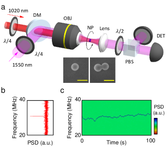
In this experiment, we optically trap a silica nanoparticle (a nanosphere or a nanodumbbell) in a vacuum chamber using a tightly focused 1550 nm laser (Fig. 1). The polarization of the trapping laser is controlled with a quarter waveplate. An additional 1020 nm laser is used to apply an external torque that will be measured. The trapping laser passes a collimation lens and is guided to balanced photo detectors that monitor the rotational, torsional, and the center-of-mass motions of the levitated nanoparticle. When the nanoparticle rotates, it changes the polarization of the trapping laser slightly, which is monitored with a balanced photo detector after a polarizing beam splitter (Fig. 1(a)). The signal of the balanced detector is sent to a spectrum analyzer to measure the rotation frequency.
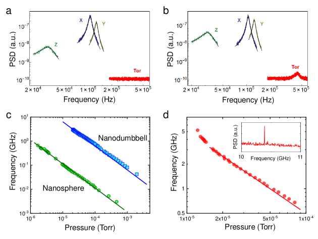
Once a nanoparticle is trapped in a linearly-polarized 1550 nm laser, we collect the power spectral density (PSD) signals of its motion at 10 torr to verify its geometry (Ahn et al., 2018). Fig. 2(a) shows the PSD’s of the motion of a nanosphere. The ratio of the damping rates in directions perpendicular and parallel to the electric field of the laser is measured to be , which agrees well with the expected value of 1 for a sphere. There is no observable torsional peak for the nanosphere. On the other hand, the PSD of a nanodumbbell has a clear torsional peak as shown in Fig. 2(b). The measured damping ratio is for this nanodumbbell, which agrees with the expected value of 1.27 (Ahn et al., 2018).
After the geometry of a levitated nanoparticle is confirmed, we change the polarization of the trapping laser from linear to circular. The angular momentum of the circularly polarized laser induces a torque on the levitated nanoparticle and drives it to rotate Ahn et al. (2018); Reimann et al. (2018). The rotation speed is determined by the balance between the optical torque and the drag torque from the surrounding air. Thus the rotation speed is inversely proportional to the air pressure, as shown in Fig. 2(c). The rotation speed of a nanodumbbell is much faster than that of a nanosphere with the same diameter in the same trap at the same pressure. This is because the optical torque on the nanodummbell is much larger than that on the nanosphere due to their different shapes. Fig.2(d) shows the fastest rotation frequency observed in our experiment so far. The rotation rate reaches 5.2 GHz at torr before the nanoparticle is lost from the optical trap. This is the fastest nanorotor reported to date.
Besides observing the fastest rotation, we employ the nanorotor as an ultrasensitive torque sensor. To test its performance, we use an additional 1020 nm laser to apply an external torque. If we modulate the 1020 nm laser sinusoidally, the net torque applied on the nanorotor is
| (1) |
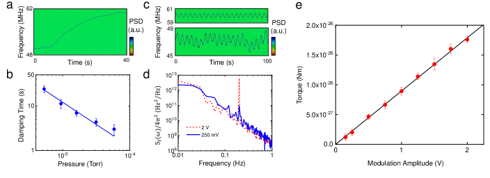
where is the dc component of the optical torque which mainly comes from the trapping beam, is the external ac torque drive from the 1020 nm laser, is the frequency of the modulation, is the thermal fluctuation torque, is the moment of inertia of the nanorotor, is the angular rotation velocity of the nanoparticle, is the rotational damping rate because of residual air molecules. If we ignore the thermal noise , we have after the modulated external torque is turned on for a long time. Here is the average rotation frequency and . The rotational damping rate can be measured experimentally. We can suddenly turn on the 1020 nm laser and measure the rotation frequency as a function of time (Fig. 3(a)). The collected data is fit with an exponential curve . Here, is the initial rotation frequency, is the terminal rotation frequency, is the time when the 1020 nm laser is turned on, and is the damping time. From the fitting, we determine the damping time. The measured damping time at different pressures are plotted in Fig.3(b). Then the external AC torque can be measured by observing the change of the rotation frequency as a function of time. The sensitivity of measuring an external torque will be limited by the thermal noise torque .
Including the effects of the thermal noise, the single-sided power spectrum density of the time-dependent angular velocity for a measurement time of is
| (2) |
is the Boltzmann constant, and is the temperature. Note that can be calculated from the time-dependent rotation frequency (Fig. 3(c)) measured by a spectrum analyzer directly. This is very different from the case of the center-of-mass motion, where a calibration factor is required to convert a measured voltage signal to the real position Ricci et al. (2019). From the at the modulation frequency, we can measure the external AC torque applied to the nanorotor. Because of the thermal noise, the minimum external torque that can be measured is Xu and Li (2017); Bernard et al. (1985).
We now measure the external torque exerted by the circularly polarized 1020 nm laser according to Eq. 2. We modulate the laser power with a sinusoidal signal at 200 mHz while we measure the rotational PSD of the nanorotor in real time (bottom subfigure in Fig.3(c)). For reference, we simultaneously monitor a RF signal generated by a voltage-controlled oscillator modulated sinusoidally at the same time (top subfigure in Fig.3(c)). We repeat the measurement for different modulation amplitudes. Each measurement takes 100 seconds. The resulting PSD of the angular velocity are shown in Fig.3(d). We can then calculate the amplitude of the external torque using the PSD and the measured damping time. The minimum resolvable torque corresponds to the value obtained with no modulation. This is about for a measurement time of 100 seconds at torr. This corresponds to a measured sensitivity of , which is comparable to the theoretical thermal-noise limited sensitivity of at torr at 300K. The measured sensitivity is several orders improved compared to the state-of-the-art nanofabricated torque sensor in a cryogenic environment Kim et al. (2016). As shown in Fig.3(e), we measured an external torque as small as when the modulation amplitude is 0.15 V.
One important application of our ultrasensitive torque sensor with an optically levitated nanorotor will be to detect the long-sought vacuum friction Kardar and Golestanian (1999); Manjavacas and García de Abajo (2010); Zhao et al. (2012); Manjavacas et al. (2017). Quantum and thermal vacuum fluctuations will create instantaneous charges on the surface of an otherwise neutral nanosphere. If the nanosphere rotates at a high speed, these instantaneous charges will generate radiation, which causes a noncontact friction. The vacuum friction is extremely weak in free space Manjavacas and García de Abajo (2010), but can be enhanced by a nearby surface with a large local density of electromagnetic states Zhao et al. (2012); Manjavacas et al. (2017). We perform numerical calculations to find the suitable conditions to detect the vacuum friction. Assuming that a nanosphere is located at a distance from the surface and rotates at an angular velocity of around an axis parallel to the substrate, the vacuum frictional torque is Zhao et al. (2012); Manjavacas et al. (2017):
| (3) |
where is the Bose-Einstein distribution function at temperature . For simplicity, we assume the temperatures of the nanosphere () and the substrate () are the same in our calculation. is the electrical polarizability of the nanosphere. , where and are electromagnetic Green tensor components Zhao et al. (2012). is the axis of rotation. From Eq. 3, we can find that the imaginary part of the polarizability contributes to the vacuum friction.
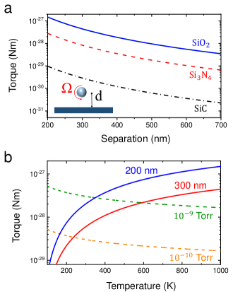
We calculate the vacuum frictional torque on a 75 nm-radius silica nanosphere near three different substrates (silica (SiO2), Si3N4, and SiC) at different separations and temperatures (Fig. 4). These materials support phonon polaritons. Their dielectric functions can be descibed by the Drude-Lorentz model Zhao et al. (2012); Manjavacas et al. (2017); Kischkat et al. (2012). For rotation frequencies much smaller than , is proportional to the rotation frequency. Inspired by our experimental results, we assume the rotation frequency to be 1 GHz in the calculation. As shown in Fig. 4(a), a silica surface will give the largest vacuum friction for a rotating silica nanosphere because their phonon polariton modes match. The vacuum frictional torque can be close to Nm at small separations, which is comparable to what we have measured in this experiment. Smaller torques can be measured at lower pressures and for longer times. We also calculated the air damping torque on a rotating nanosphere due to residual air molecules in the vacuum chamber at different pressures. The vacuum friction increases when the temperature increases, while the air damping torque decreases when the temperature increases if the air presure is constant (Fig. 4(b)). At torr, the vacuum frictional torque is larger than the air damping torque when the temperature of the subrate and the nanosphere is larger than 350K at 200 nm separation, or larger than 590 K at 300 nm separation. These temperatures should be easy to achieve. Similar pressures have also been achieved in levitation experiments Slezak et al. (2018); Tebbenjohanns et al. (2019). Therefore, the detection of the vacuum friction with an optically levitated nanorotor torque sensor is feasible under realistic conditions.
In conclusion, we have demonstrated an ultrasensitive torque sensor with an optically levitated nanorotor in vacuum. We measure a record small torque of and achieve a record high rotational speed exceeding 5 GHz for a nanorotor. The measured torque sensitivity of our system at room temperature is several orders better than that of the state-of-the-art nanofabricated torque sensor at mK temperatures Kim et al. (2016). Our system will be suitable to detect the quantum vacuum friction Kardar and Golestanian (1999); Manjavacas and García de Abajo (2010); Zhao et al. (2012); Manjavacas et al. (2017). If the rotating nanoparticle contains an electron spin (e.g. a diamond nitrogen-vacancy center), it can study the quantum geometric phase Chen et al. (2019). It can also study nanoscale magnetism, especially the Einstein-de Haas effect and the Barnett effect Losby et al. (2018).
Acknowledgments
We thank helpful discussions with F. Robicheaux, T. Seberson, R. Zhao, Z. Jacob, Q. Han, and R. M. Ma. We are grateful to supports from the Office of Naval Research under grant No. N00014-18-1-2371, the NSF under grant No. PHY-1555035, and the Defense Advanced Research Projects Agency (DARPA).
References
- Cavendish (1798) H. Cavendish, Philos. Trans. R. Soc. London 88, 469 (1798).
- Wu et al. (2017) M. Wu, N. L.-Y. Wu, T. Firdous, F. F. Sani, J. E. Losby, M. R. Freeman, and P. E. Barclay, Nature Nanotechnology 12, 127 (2017).
- Losby et al. (2018) J. E. Losby, V. T. K. Sauer, and M. R. Freeman, Journal of Physics D: Applied Physics 51, 483001 (2018).
- Chan et al. (2001) H. B. Chan, V. A. Aksyuk, R. N. Kleiman, D. J. Bishop, and F. Capasso, Science 291, 1941 (2001).
- He et al. (2016) L. He, H. Li, and M. Li, Science Advances 2, e1600485 (2016).
- Kim et al. (2016) P. H. Kim, B. D. Hauer, C. Doolin, F. Souris, and J. P. Davis, Nature Communications 7, 13165 (2016).
- Kardar and Golestanian (1999) M. Kardar and R. Golestanian, Rev. Mod. Phys. 71, 1233 (1999).
- Manjavacas and García de Abajo (2010) A. Manjavacas and F. J. García de Abajo, Phys. Rev. Lett. 105, 113601 (2010).
- Zhao et al. (2012) R. Zhao, A. Manjavacas, F. J. García de Abajo, and J. B. Pendry, Phys. Rev. Lett. 109, 123604 (2012).
- Manjavacas et al. (2017) A. Manjavacas, F. J. Rodríguez-Fortuño, F. J. G. de Abajo, and A. V. Zayats, Phys. Rev. Lett. 118, 133605 (2017).
- Chen et al. (2019) X.-Y. Chen, T. Li, and Z.-Q. Yin, Science Bulletin 64, 380 (2019).
- Yin et al. (2013) Z.-Q. Yin, A. A. Geraci, and T. Li, International Journal of Modern Physics B 27, 1330018 (2013).
- Ranjit et al. (2016) G. Ranjit, M. Cunningham, K. Casey, and A. A. Geraci, Phys. Rev. A 93, 053801 (2016).
- Rider et al. (2016) A. D. Rider, D. C. Moore, C. P. Blakemore, M. Louis, M. Lu, and G. Gratta, Phys. Rev. Lett. 117, 101101 (2016).
- Tebbenjohanns et al. (2019) F. Tebbenjohanns, M. Frimmer, A. Militaru, V. Jain, and L. Novotny, Phys. Rev. Lett. 122, 223601 (2019).
- Arita et al. (2013) Y. Arita, M. Mazilu, and K. Dholakia, Nature Communications 4, 2374 (2013).
- Kuhn et al. (2017) S. Kuhn, B. A. Stickler, A. Kosloff, F. Patolsky, K. Hornberger, M. Arndt, and J. Millen, Nature Communications 8, 1670 (2017).
- Ahn et al. (2018) J. Ahn, Z. Xu, J. Bang, Y.-H. Deng, T. M. Hoang, Q. Han, R.-M. Ma, and T. Li, Phys. Rev. Lett. 121, 033603 (2018).
- Reimann et al. (2018) R. Reimann, M. Doderer, E. Hebestreit, R. Diehl, M. Frimmer, D. Windey, F. Tebbenjohanns, and L. Novotny, Phys. Rev. Lett. 121, 033602 (2018).
- Monteiro et al. (2018) F. Monteiro, S. Ghosh, E. C. van Assendelft, and D. C. Moore, Phys. Rev. A 97, 051802 (2018).
- Rider et al. (2019) A. D. Rider, C. P. Blakemore, A. Kawasaki, N. Priel, S. Roy, and G. Gratta, Phys. Rev. A 99, 041802 (2019).
- Hoang et al. (2016) T. M. Hoang, Y. Ma, J. Ahn, J. Bang, F. Robicheaux, Z.-Q. Yin, and T. Li, Phys. Rev. Lett. 117, 123604 (2016).
- Rashid et al. (2018) M. Rashid, M. Toroš, A. Setter, and H. Ulbricht, Phys. Rev. Lett. 121, 253601 (2018).
- Li et al. (2010) T. Li, S. Kheifets, D. Medellin, and M. G. Raizen, Science 328, 1673 (2010).
- Millen et al. (2014) J. Millen, T. Deesuwan, P. Barker, and J. Anders, Nature Nanotechnology 9, 425 (2014).
- Gieseler et al. (2014) J. Gieseler, R. Quidant, C. Dellago, and L. Novotny, Nature Nanotechnology 9, 358 (2014).
- Hoang et al. (2018) T. M. Hoang, R. Pan, J. Ahn, J. Bang, H. T. Quan, and T. Li, Phys. Rev. Lett. 120, 080602 (2018).
- Xu and Li (2017) Z. Xu and T. Li, Phys. Rev. A 96, 033843 (2017).
- Ricci et al. (2019) F. Ricci, M. T. Cuairan, G. P. Conangla, A. W. Schell, and R. Quidant, Nano letters (2019), 10.1021/acs.nanolett.9b00082.
- Bernard et al. (1985) B. E. Bernard, L. I. Winkler, and R. C. Ritter, Metrologia 21, 115 (1985).
- Kischkat et al. (2012) J. Kischkat, S. Peters, B. Gruska, M. Semtsiv, M. Chashnikova, M. Klinkmüller, O. Fedosenko, S. Machulik, A. Aleksandrova, G. Monastyrskyi, Y. Flores, and W. T. Masselink, Appl. Opt. 51, 6789 (2012).
- Slezak et al. (2018) B. R. Slezak, C. W. Lewandowski, J.-F. Hsu, and B. D’Urso, New Journal of Physics 20, 063028 (2018).