[a]University of Birmingham,
Birmingham, B15 2TT, United Kingdom
\affiliation[b]IRRAD Proton Facility,
CERN, CH-1211 Geneva 23, Switzerland
\affiliation[c]Institute of Experimental Particle Physics, Karlsruhe Institute of Technology,
Karlsruhe, D-76131, Germany
\emailAddk.nikolopoulos@bham.ac.uk
Experimental Determination of Proton Hardness Factors at Several Irradiation Facilities
Abstract
The scheduled High Luminosity upgrade of the CERN Large Hadron Collider presents new challenges in terms of radiation hardness. As a consequence, campaigns to qualify the radiation hardness of detector sensors and components are undertaken worldwide. The effects of irradiation with beams of different particle species and energy, aiming to assess displacement damage in semiconductor devices, are communicated in terms of the equivalent MeV neutron fluence, using the hardness factor for the conversion. In this work, the hardness factors for protons at three different kinetic energies have been measured by analysing the I–V and C–V characteristics of reverse biased diodes, pre- and post-irradiation. The sensors were irradiated at the MC40 Cyclotron of the University of Birmingham, the cyclotron at the Karlsruhe Institute of Technology, and the IRRAD proton facility at CERN, with the respective measured proton hardness factors being: for MeV, for MeV, and for GeV. The hardness factors currently used in these three facilities are in agreement with the presented measurements.
1 Introduction
The scheduled upgrade of the CERN Large Hadron Collider [1] to its High Luminosity phase (HL–LHC) in 2024 [2] presents new challenges in terms of detector radiation hardness [3, 4]. In irradiation facilities around the world, campaigns to qualify radiation hardness of detector sensors are undertaken. Standard MeV neutron equivalent fluences are used for the purpose of inter-facility comparison and collaboration. The experimentally determined proton fluences at given energies are converted to the standardised fluences using the corresponding hardness factor. This factor is usually derived by evaluating the leakage current in the bulk of a silicon sensor; assuming that the measured leakage current is scaling with the non-ionizing energy loss (NIEL).
At the University of Birmingham, the MC40 cyclotron adopts a hardness factor value of 2.2 [5] for protons of MeV. However, for beams of similar kinetic energy, facilities have obtained different values. For example, the Irradiation Center Karlsruhe has recorded a value of for MeV protons, with a previously assumed value of 1.85 for MeV protons [6]. Other studies have claimed similar values, such as 2.22 for MeV protons [7]. Tabulated values from the RD50 Collaboration, which is concerned with the development of radiation hard semiconductor devices for high luminosity colliders [8], give a value of approximately for MeV protons [9]. For GeV protons, a value of 0.62 has been measured at the IRRAD proton facility [7]. Due to these discrepancies, further study on the value of the hardness factor is required. Moreover, the large uncertainties of these measurements result to large uncertainties when the proton fluences are converted to the corresponding MeV neutron equivalent fluences.
In this article the current-voltage (I–V) and capacitance-voltage (C–V) characteristics of reversed biased BPW34F photodiodes are analysed to obtain proton hardness factors for protons of three different kinetic energies. In the following the irradiation facilities are presented briefly in Sec. 2, while the description of the measurements is given in Sec. 3. The obtained results are presented in Sec. 4, while a concluding discussion is given in Sec. 5.
2 Irradiations
2.1 MC40 Cyclotron
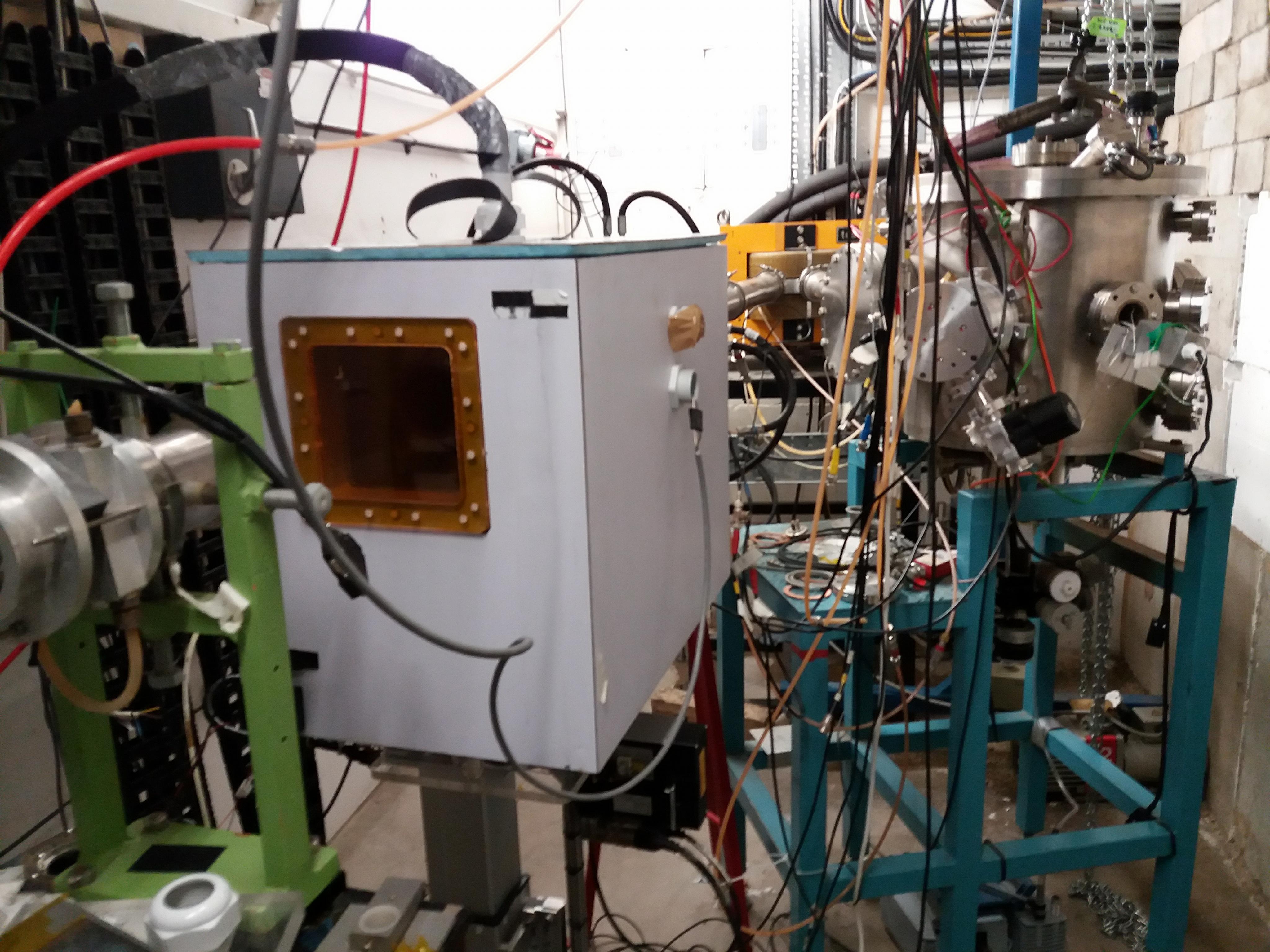
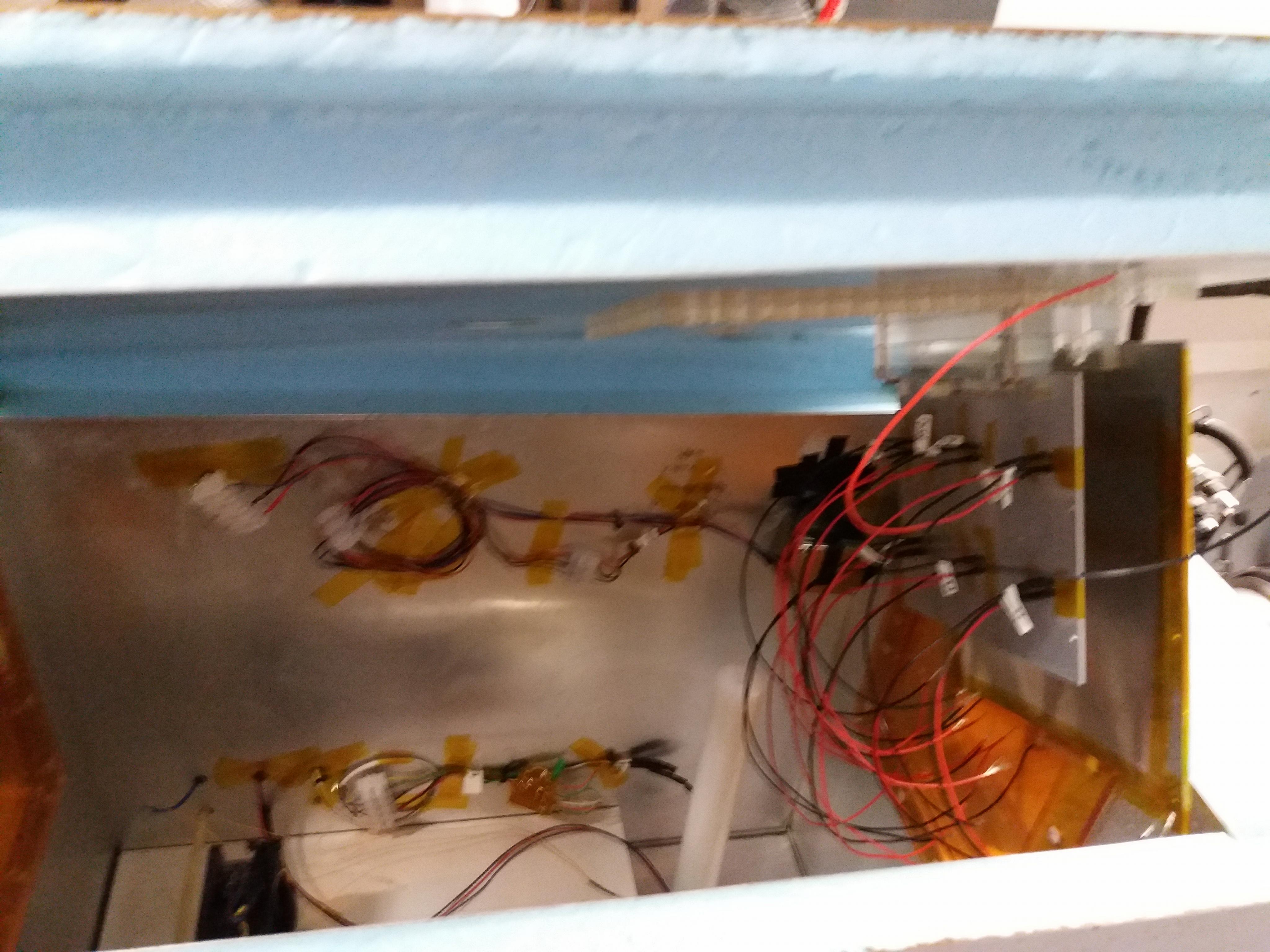
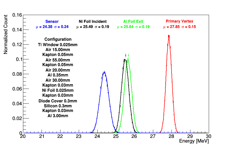
The MC40 cyclotron at the University of Birmingham is primarily used for the production of medical isotopes. However, it is regularly used for nuclear physics research and radiation damage studies. The configuration utilised for high intensity proton irradiations is shown in Fig. 1. The beam spot is a square of area mm2, and its position is calibrated before each irradiation session with gafchromic film. The sample is isolated from the environment using a temperature controlled chamber, which is is mounted on a XY-axis robotic scanning system controlled via LabView. The chamber temperature during irradiation is set to C, this is selected to ensure that the sample temperature remains well below C, even when irradiated at the highest available dose rate in the facility, and thus there will be no significant contribution to thermal annealing. Further details for the irradiation facility are provided in Ref. [10].
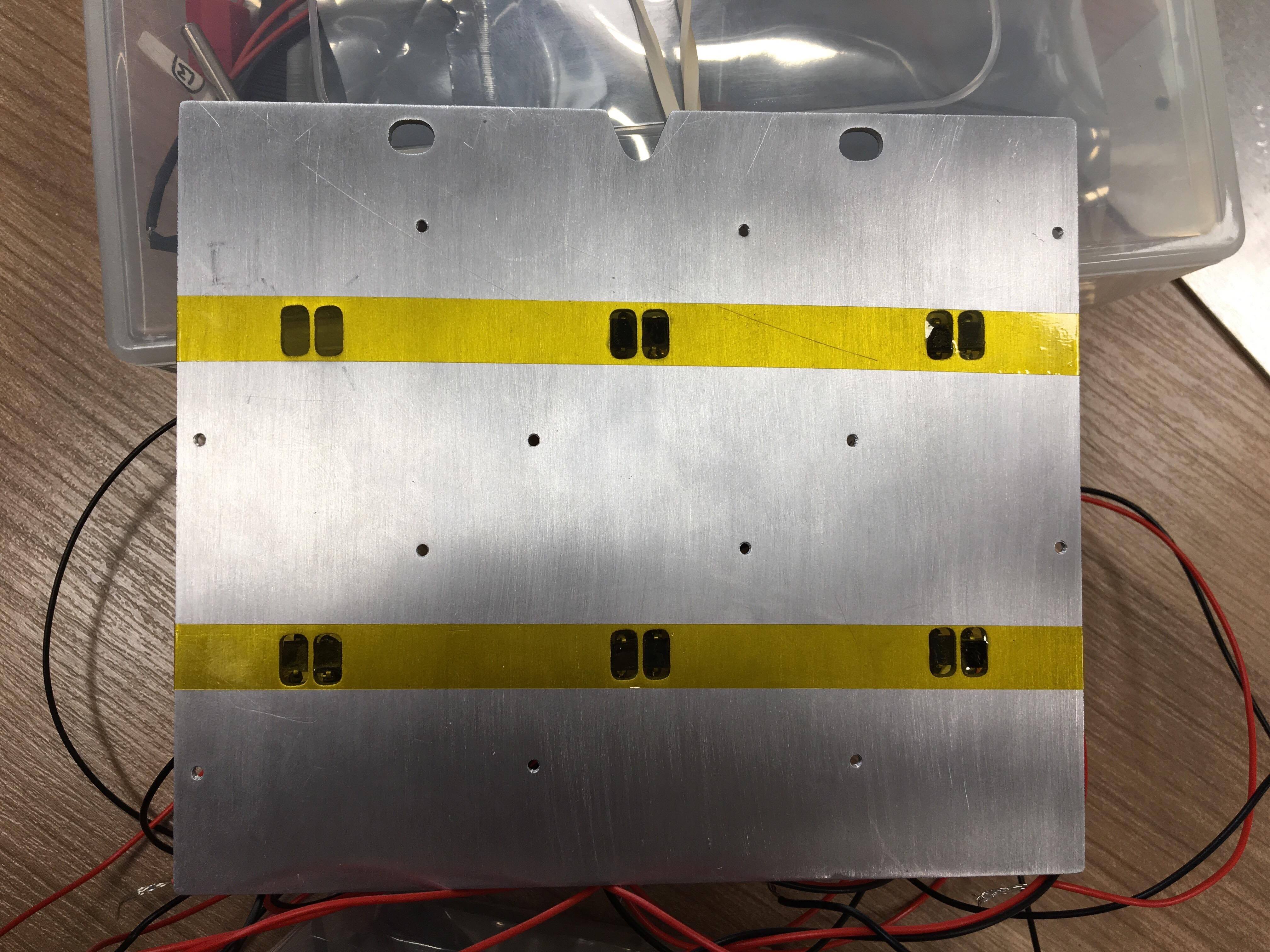
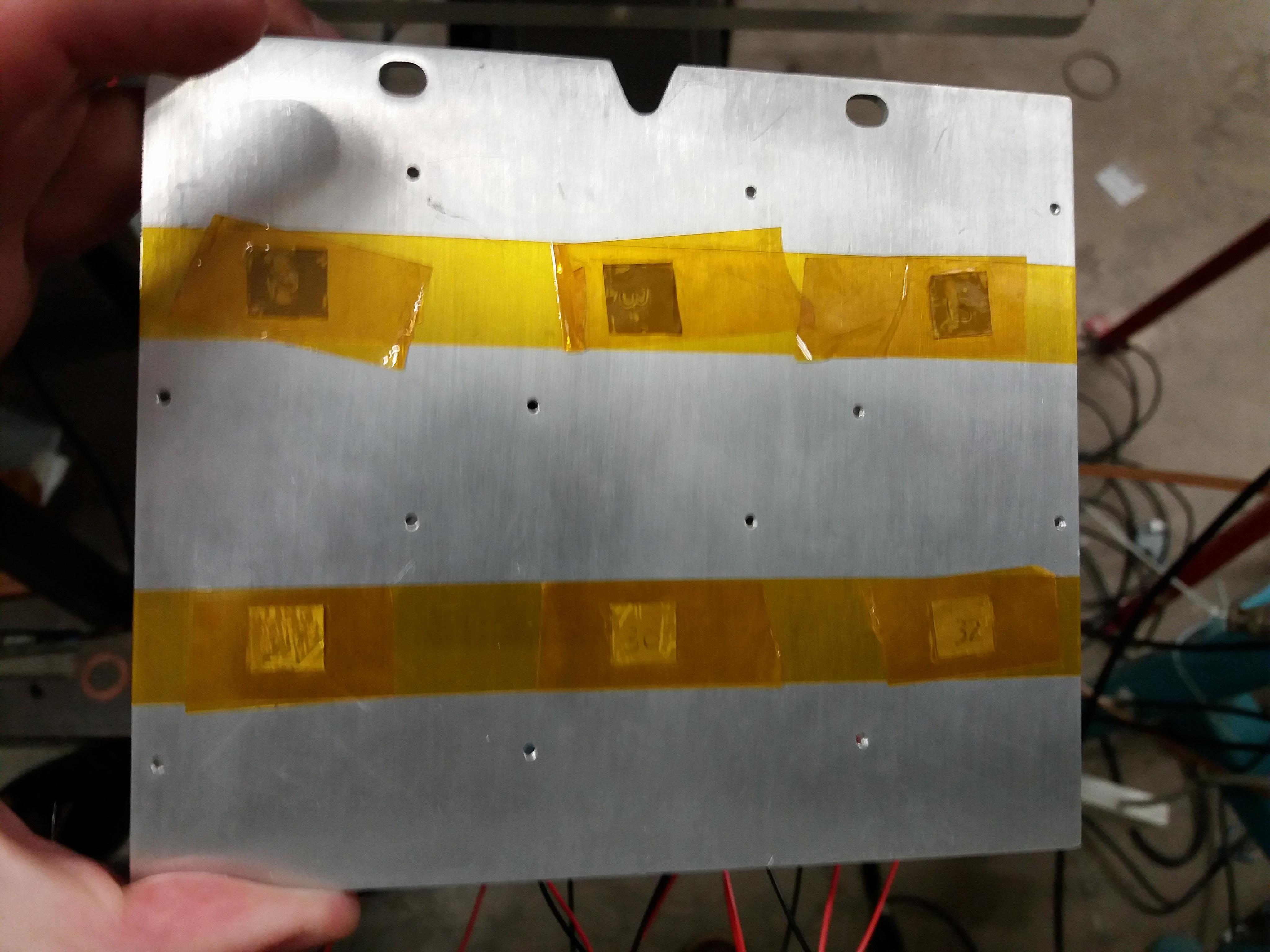
The irradiated sample consists of an aluminium plate with twelve slots for diodes, mounted in pairs, as shown in Fig. 2. In front of each pair of diodes, 57Ni foils are installed and their activity after irradiation is used to estimate the delivered proton fluence. Inside the temperature controlled chamber, the sample and the foils, are placed behind a m thick sheet of aluminium to block possible low energy components of the beam. The energy of the proton beam when they reach the sample, is estimated using a Geant4-based [11, 12] simulation, as shown in Fig. 3.
2.2 IRRAD Proton Facility
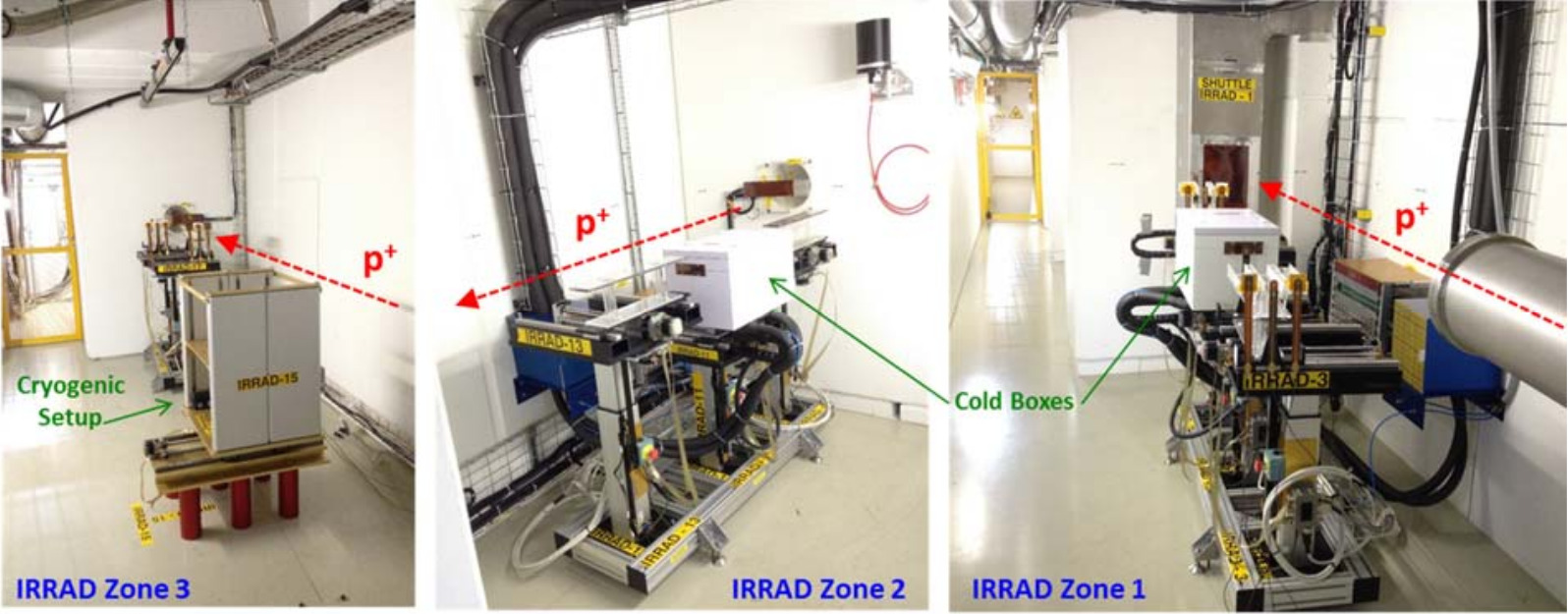
The IRRAD proton facility at CERN utilises a primary proton beam with an energy of GeV, extracted from the proton synchrotron [13]. The facility employs the use of a remote controlled stage to adjust the position of the sample, and an isolated box for humidity and temperature control down to approximately C [14]. The proton fluence determination for IRRAD is performed with aluminium foils. Figure 4 shows an image of the IRRAD setup and the remote controllable tables, which can move in the transverse and azimuthal directions to align the sample with the beam. This setup also allows for beam scanning, which can be done automatically. Furthermore, there are three blocks of three tables along the beam line, each separated by thick blocks of concrete.
For this study, both BPW34F photodiodes and FZ pad diodes were irradiated to the same fluences for NIEL comparisons. Irradiations take place at room temperature, and given the dose rate on the samples no appreciable thermal annealing is expected to take place, in particular when compared to the thermal annealing applied during the analysis procedure, see § 3.1.
2.3 Irradiation Center Karlsruhe
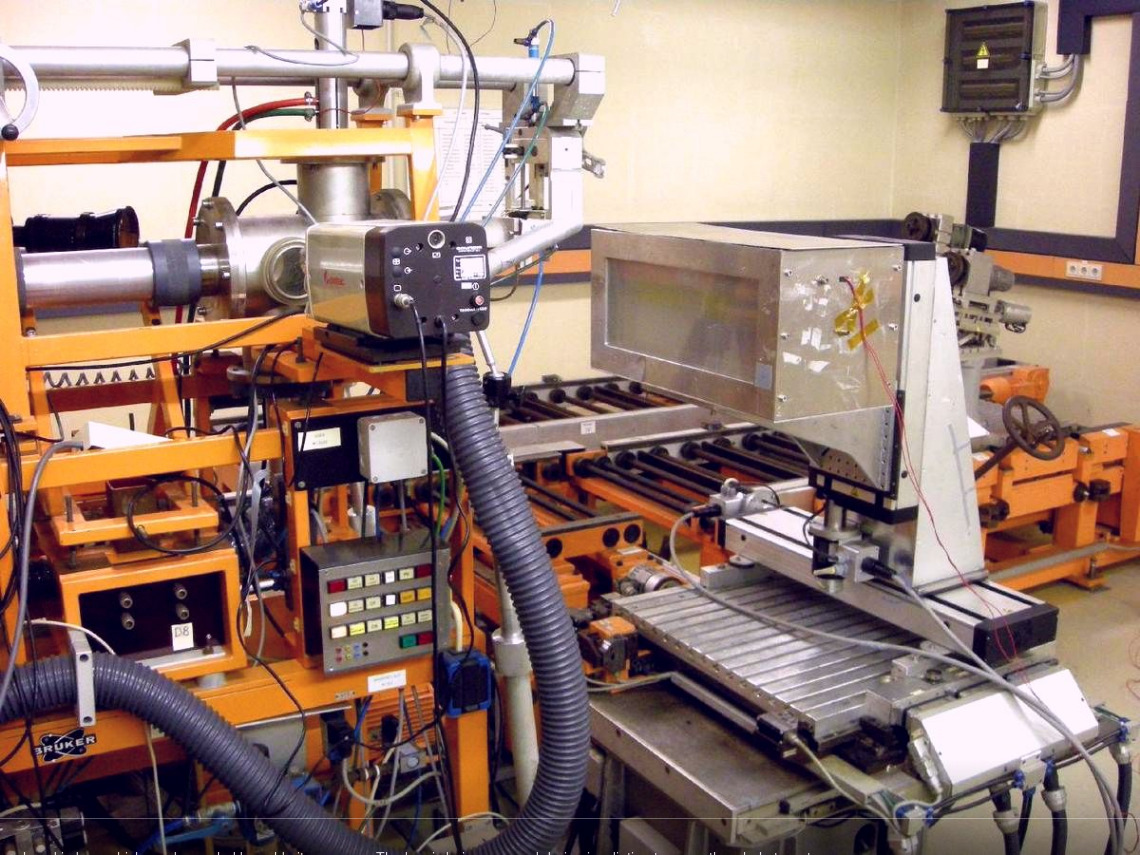
The Irradiation Center Karlsruhe [16] accesses a compact cyclotron operated by ZAG Zyklotron AG [17], a private-owned company specialising in radioisotopes production for medicine and engineering. The cyclotron accelerates protons to MeV and for this study the energy of the protons at the sample was measured to be MeV. The set-up utilised for irradiations is shown in Fig. 5. Similarly to the MC40 cyclotron and the IRRAD proton facility, the sample can be positioned within an isolation box for humidity and temperature control down to C [16], and the fluences are calculated using 57Ni foils.
3 Measurements
3.1 Thermal Annealing Procedure
Since the degree of thermal annealing significantly affects the post-irradiation leakage current of photodiodes, all diodes where thermally annealed for 80 minutes at C in accordance with the guidelines of the RD50 collaboration. This ensured that post-irradiation, all diodes possessed the same thermal history. The process itself utilised a pre-heated oven, monitored with a NiCr-NiAl thermocouple. For the MC40 cyclotron, due to the large number of diodes tested, thermal annealing took place in two sets, with half of the diodes in each set.
3.2 Maximum Depletion Voltage
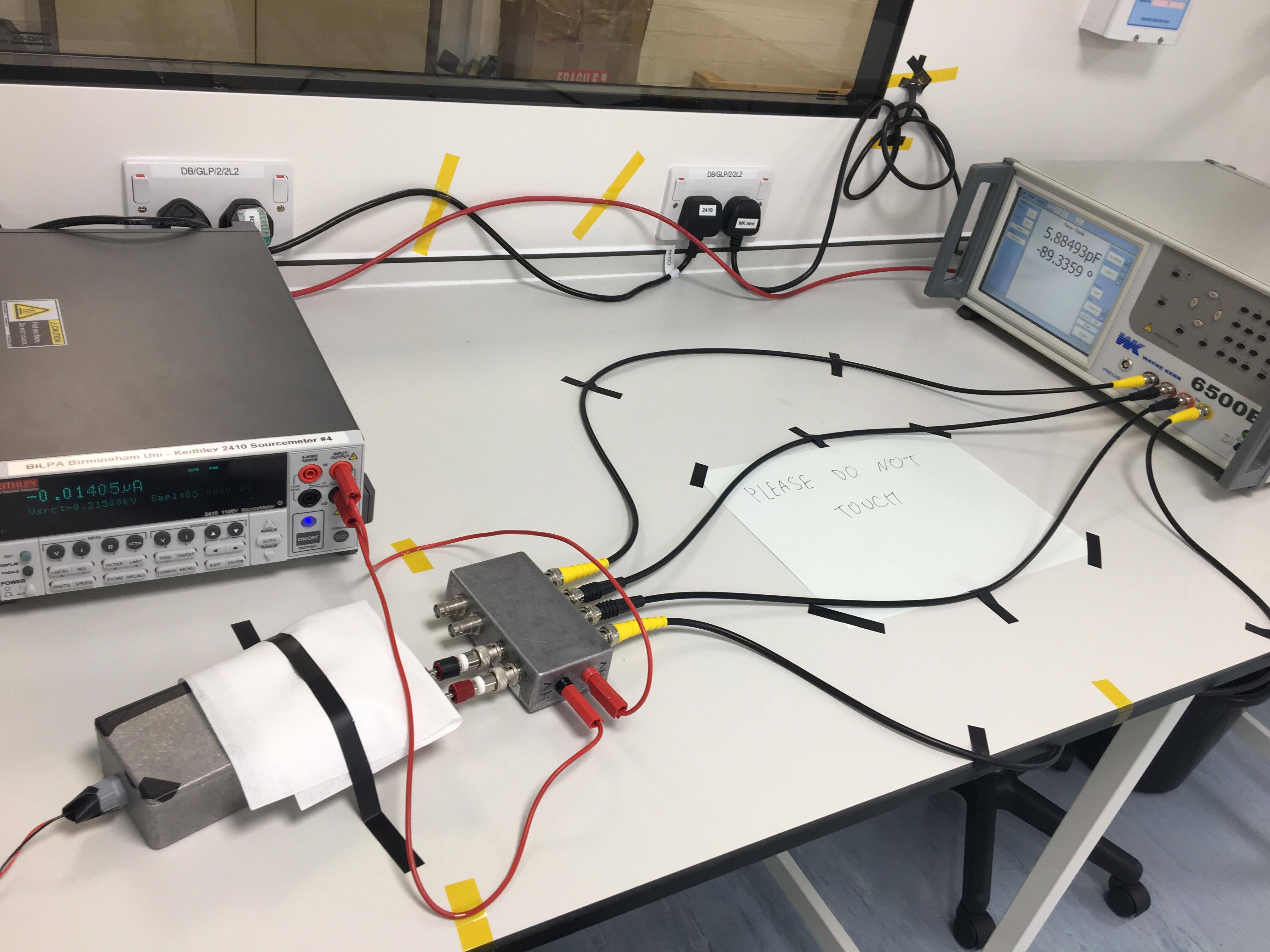
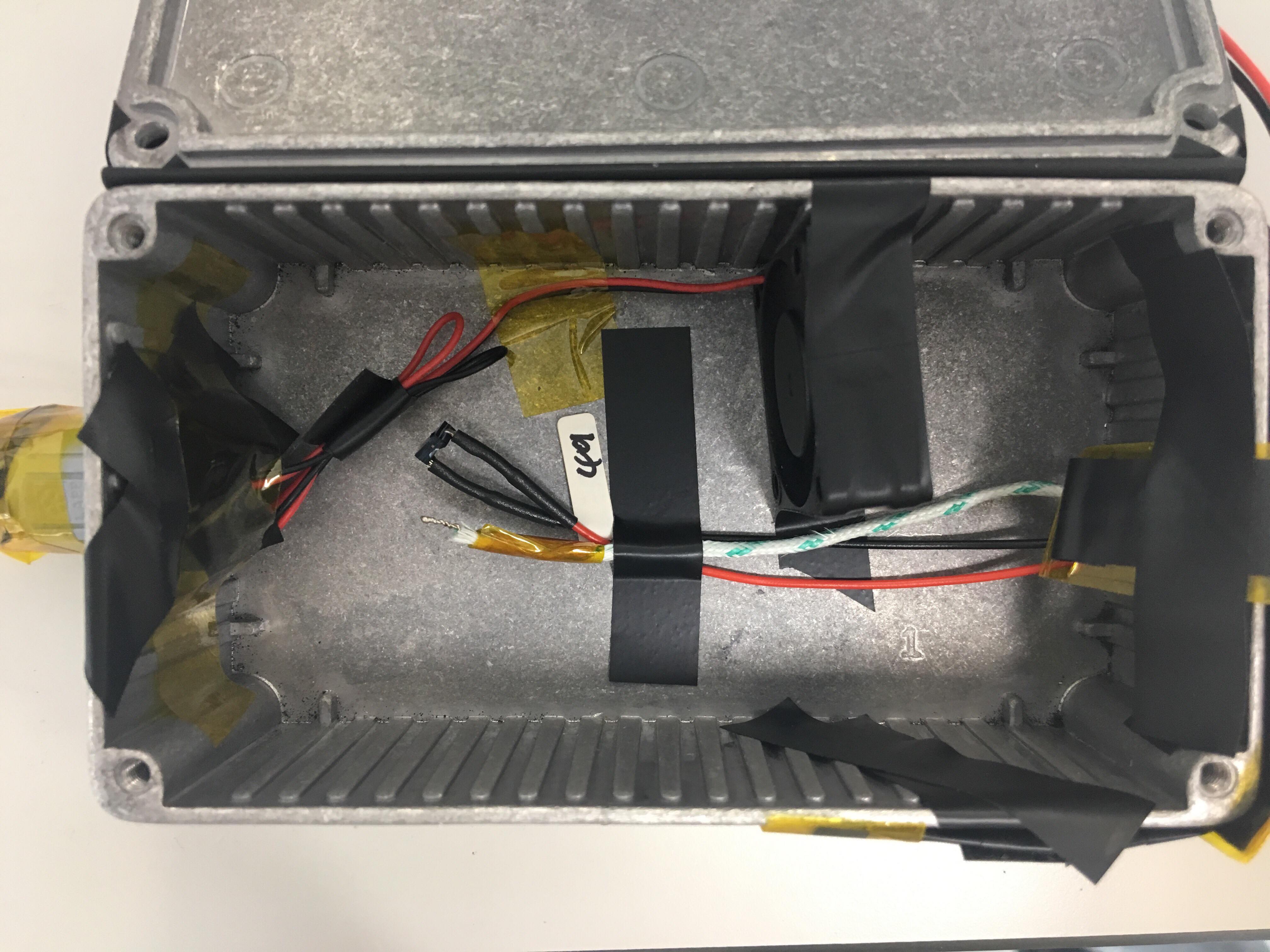
To estimate the value of the voltage where maximum depletion is achieved, the diodes were placed inside an aluminium box for radiation shielding, as shown in Fig. 6, alongside a fan for air circulation. The system was then connected to a Wayne-Kerr 6500B Precision Impedance Analyser via a junction box and four coaxial cables for capacitance readings at 10 kHz; in accordance with RD50 guidelines. An external bias was supplied to the diodes by a Keithley 2410 Sourcemeter. The system was then trimmed to approximately zero capacitance with the diode unconnected before each set of data was taken.
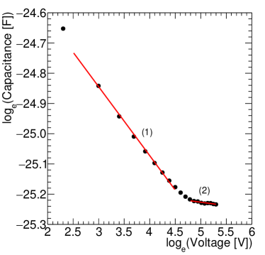
For a p-n junction, before full depletion, the capacitance is inversely proportional to the square root of the voltage. Following full depletion, capacitance becomes independent of the voltage. Using this, it is possible to estimate the voltage at which a diode becomes fully depleted, referred to as the maximum depletion voltage. Figure 7 shows a plot of capacitance as a function of voltage in logarithmic scales. In region (1), the diode is not fully depleted, whilst in region (2), full depletion has been achieved. In the latter region, the gradient is not zero as the BPW34F diode does not contain a guard ring, and thus lateral depletion is still occurring. By fitting the two regions linearly, the maximum depletion voltage is estimated as the intercept of the two lines. This estimate was performed for every diode following irradiation and annealing.
3.3 Quantifying Radiation Damage
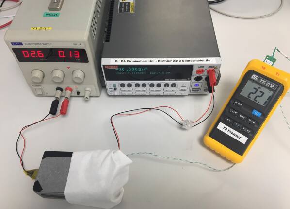
Figure 8 shows the experimental setup used for I–V measurements. Similarly to the capacitance measurements, the diodes were placed within an aluminium box alongside a fan. A Keithley 2410 source meter was used to apply a reverse bias across the diode, which was then measured and displayed the corresponding current. A NiCr-NiAl thermocouple was used to record the temperature within the box, being placed close to the diode to obtain an accurate reading of its temperature.
Although the ambient temperature, , during data taking did not deviate substantiall from C, to minimise any effects due to the temperature dependence of the leakage current, all I–V curves were normalised to the reference temperature, , of C, following RD50 recommendations. The formula used is given in Eq. 1, where is the activation energy of silicon, which is closely related to the band gap energy of silicon, and all other symbols have their usual meanings.
| (1) |
Over the temperature range relevant for this study, has a value of eV [18]. Post-irradiation, the leakage current of the diodes increased proportionally to the incident fluence due to induced defects in the silicon [19]. Hence, the change in leakage current pre- and post- irradiation can be used as a measure of the degree of radiation damage. Assuming that the leakage current scaled with the NIEL irrespective of the particle species and energy, the change in leakage current can be used to determine the hardness factor.
3.4 Determination of Hardness Factors
The change in leakage current pre- and post- irradiation, , as a function of fluence, is:
| (2) |
where is the current related damage rate, is the active area of silicon, and is the width of the depletion region. For BPW34F photodiodes, cm2 [20, 21] and m [22]. From equation 2, and the NIEL scaling hypothesis, it follows that the hardness factor can be written as:
| (3) |
where is the MeV neutron equivalent fluence. Combining equations 2 and 3, the hardness factor can be obtained as:
| (4) |
where is the current related damage rate for 1 MeV neutrons. In this study, Acm-1 was used [19]. Thus, by comparing the diode leakage current pre- and post-irradiation as a function of fluence, the hardness factor of the incident beam is calculated.
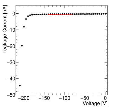
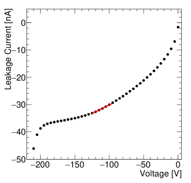
Figure 9 shows I–V curves for the same diode pre- and post-irradiation and annealing. The data were fit with a first order polynomial centred at the minimum voltage value for which the depletion region is maximised, as determined from C–V measurements. The change in leakage current, evaluated at this voltage, was computed for each diode and plot as a function of fluence.
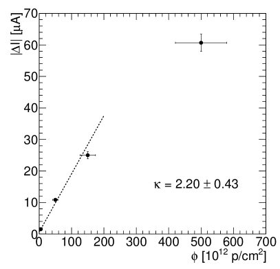
Finally, the range of validity of Eq. 2 has been considered in a dedicated study at the MC40 cyclotron. As shown in Fig. 10, the change in leakage current is linear as a function of fluence up to fluences of approximately pcm-2. At low fluences, all charge carriers generated by the radiation-induced defects are transported to the electrodes and contribute fully to the leakage current (Shockley-Read-Hall mechanism). At high fluences the high defect concentration results to charge carriers getting trapped. As a result, these are not transported throughout the sensor, which results to the observed plateau of the change in leakage current versus fluence.

4 Results
The measured change in leakage current as a function of the fluence for BPW34F photodiodes, irradiated with MeV protons at the MC40 cyclotron, are shown in Fig. 11(a). The data were fit with a straight line, which was required to pass through the origin. As there should be no change in leakage current, unless the diode is irradiated. Nevertheless, leaving the intercept free in the fit, did not significantly change the result. Using equations 2 and 4, a hardness factor value of was determined.

The measured as a function of fluence for a collection of BPW34F and BPW34FS diodes irradiated with 23 MeV protons at the Irradiation Center Karlsruhe is presented in Fig. 11(b). For these data, the fit was not forced through zero, as the pre-irradiation state for each diode was not known. However, the change in leakage current between the pre- and post-irradiated case is of several orders of magnitude, and so the change in leakage current was approximated to the post-irradiated leakage current following thermal annealing. Furthermore, given the discussion in Sec. 3.4, the highest fluence point of Fig. 11(b) was omitted from the fit. Applying equations 2 and 4 as before, a value of was determined.
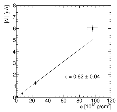
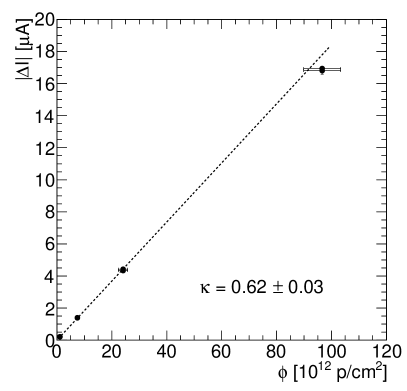
Figure 11(c) shows the change in leakage current as a function of fluence for BPW34F photodiodes irradiated with GeV protons at the IRRAD proton facility. Again, the data were fit with a first order polynomial that was required to go through the origin. From this, a value of was obtained. In Fig. 11(d) the corresponding results for FZ pad diodes, irradiated to the same fluences at IRRAD, are presented. A value of was obtained from these data.
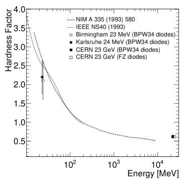
In Fig. 12 the obtained measured values of the hardness factor are compared with the tabulated values found in the literature [23, 24, 9]. It is noted that the significantly larger uncertainties on the hardness factor for 23 and 24 MeV protons stems from uncertainties in the dosimetry, and, specifically, the uncertainty on the cross-section of the 28NiNi57 process which is taken conservatively to be approximately 20% based on the spread of cross-section measurements. Thanks to the higher proton energy, dosimetry at IRRAD is performed using aluminium foils, with the respective cross-setion uncertainty taken to be approximately 7% [25, 26]. As a result, these measurements could benefit from improved dosimetry, potentially through the use of a, specifically designed, transmission ionisation chamber that could operate at large beam currents.
In the future, it is of interest to supplement this work with measurements at additional energies, for example the Cyclotron RadioIsotope Center (CYRIC) at Tohoku University [27] and the Los Alamos Neutron Science Center (LANSCE) facility [28] provide 70 and 800 MeV protons, respectively. Another development could involve other particle species, for example the PSI High Intensity Proton Accelerator (HIPA) provides irradiations with 300 MeV/c pions and the Jožef Stefan Institute TRIGA Mark II reactor [29, 30] provides irradiations with neutrons of a wide range of energies. An overview of the available irradiation facilities worldwide is provided by a CERN-maintained dedicated database [31].
5 Conclusions
By analysing the I–V and C–V characteristics of reverse biased BPW34F photodiodes pre- and post-irradiation, the hardness factors, , for three different proton energies were determined. Utilising the University of Birmingham MC40 cyclotron, a value of for an energy of MeV was obtained. By undertaking a similar procedure, using the IRRAD proton facility, a value of for an energy of GeV was measured. In parallel, the corresponding measurements with FZ pad diodes irradiated at IRRAD yielded a value of . Using diodes irradiated at the Irradiation Center Karlsruhe, for an energy of MeV, a value of was found. All measured values agree with the hardness factors currently in use at the facilities within one standard deviation. The measurements for and MeV protons have significantly larger uncertainties with respect to the GeV measurement. The origin of this difference is in the dosimetry, which relies on nickel foils for and MeV protons, while aluminium foils are used for the GeV protons. In the future, improved dosimetry could be achieved by using a transmission ionisation chamber, specifically designed for high rate operation.
Acknowledgements
The authors would like to acknowledge the help and support of the operations teams at the Birmingham MC40 Cyclotron, the Irradiation Center Karlsruhe, and CERN IRRAD, without which this work would not be possible. This project has been supported from the European Research Council (ERC) under the European Union’s Horizon 2020 research and innovation programme (grant agreement No. 714893). The irradiation facilities have been supported as Transnational Access Facilities by the European Union’s Horizon 2020 Research and Innovation programme (grant agreement No. 654168).
References
- [1] L. Evans and P. Bryant, “LHC Machine,” JINST, vol. 3, p. S08001, 2008.
- [2] O. Brüning and L. Rossi, “The High Luminosity Large Hadron Collider,” Adv. Ser. Direct. High Energy Phys., vol. 24, pp. pp.1–393, 2015.
- [3] ATLAS Collaboration, “Letter of Intent for the Phase-II Upgrade of the ATLAS Experiment.” CERN-LHCC-2012-022, 2012.
- [4] CMS Collaboration, “Technical Proposal for the Phase-II Upgrade of the CMS Detector.” CERN-LHCC-2015-010, 2015.
- [5] P. Dervan et al., “Upgrade to the Birmingham Irradiation Facility,” Nucl. Instrum. Meth., vol. A796, pp. 80–84, 2015.
- [6] A. Dierlamm, “Proton irradiation in karlsruhe.” RD50 Workshop in Barcelona, 2010.
- [7] M. Moll, E. Fretwurst, G. Lindstrom, and M. Kuhnke, “Relation between microscopic defects and macroscopic changes in silicon detector properties after hadron irradiation,” Nucl. Instrum. Meth., vol. B186, pp. 100–110, 2002.
- [8] RD50 Collaboration. http://rd50.web.cern.ch/rd50/.
- [9] M. Huhtinen and P. A. Aarnio, “Pion induced displacement damage in silicon devices,” Nucl. Instrum. Meth., vol. A335, pp. 580–582, 1993.
- [10] P. Allport et al., “Recent results and experience with the Birmingham MC40 irradiation facility,” JINST, vol. 12, no. 03, p. C03075, 2017.
- [11] S. Agostinelli et al., “GEANT4: A Simulation toolkit,” Nucl. Instrum. Meth., vol. A506, pp. 250–303, 2003.
- [12] J. Allison et al., “Recent developments in Geant4,” Nucl. Instrum. Meth., vol. A835, pp. 186–225, 2016.
- [13] D. Cundy and S. Gilardoni, “The Proton Synchrotron (PS): At the Core of the CERN Accelerators,” Adv. Ser. Direct. High Energy Phys., vol. 27, pp. 39–85, 2017.
- [14] V. Cindro, “World Irradiation Facilities for Silicon Detectors,” PoS, vol. Vertex2014, p. 026, 2014.
- [15] B. Gkotse, M. Glaser, M. Moll, and F. Ravotti, “IRRAD: The New 24 GeV/c Proton Irradiation Facility at CERN,” in Proceedings, 12th International Topical Meeting on Nuclear Applications of Accelerators (AccApp 2015): Washington, D.C., United States, November 10-13, 2015, pp. 182–187, 2015.
- [16] Irradiation Center Karlsruhe, Institute of Experimental Particle Physics, KIT. http://www.etp.kit.edu/english/irradiation_center.php.
- [17] ZAG Zyklotron AG. http://www.zyklotron-ag.de/en/.
- [18] A. Chilingarov, “Temperature dependence of the current generated in si bulk,” Journal of Instrumentation, vol. 8, pp. P10003–P10003, oct 2013.
- [19] M. Moll, Radiation damage in silicon particle detectors: Microscopic defects and macroscopic properties. PhD thesis, Hamburg U., 1999.
- [20] OSRAM Opto-Semiconductors, “Bpw34 silicon pin photodiode datasheet.” Available online from http://www.osram-os.com.
- [21] F. Ravotti, M. Glaser, and M. Moll, “Sensor catalogue data compilation of solid-state sensors for radiation monitoring,” Tech. Rep. CERN-TS-Note-2005-002. TS-Note-2005-002, CERN, Geneva, May 2005.
- [22] F. Ravotti, M. Glaser, M. Moll, and F. Saigne, “BPW34 Commercial p-i-n Diodes for High-Level 1-MeV Neutron Equivalent Fluence Monitoring,” IEEE Trans. Nucl. Sci., vol. 55, no. 4, pp. 2133–2140, 2008.
- [23] A. Vasilescu and G. Lindstroem, “Displacement damage in silicon, on-line compilation.” https://rd50.web.cern.ch/rd50/NIEL/.
- [24] G. P. Summers et al., “Damage correlations in semiconductors exposed to gamma, electron and proton radiations,” IEEE Trans. Nucl. Sci., vol. 40, p. 1372, 1993.
- [25] A. Curioni et al., “Single- and multi-foils 27 Al(p,3pn) 24 Na activation technique for monitoring the intensity of high-energy beams,” Nucl. Instrum. Meth., vol. A858, pp. 101–105, 2017.
- [26] M. Glaser, F. Ravotti, and M. Moll, “Dosimetry assessments in the irradiation facilities at the CERN-PS accelerator,” IEEE Trans. Nucl. Sci., vol. 53, no. 4, pp. 2016–2022, 2006.
- [27] K. Nakamura et al., “Irradiation and testbeam of KEK/HPK planar p-type pixel modules for HL-LHC,” JINST, vol. 10, no. 06, p. C06008, 2015.
- [28] Schoenberg, K. F. and Lisowski, P. W., “LANSCE:A Key Facility for National Science and Defense,” Los Alamos Science, vol. 30, pp. 2–17, 2006.
- [29] S. Aghara and W. Charlton, “Characterization and quantification of an in-core neutron irradiation facility at a triga ii research reactor,” Nuclear Instruments and Methods in Physics Research Section B: Beam Interactions with Materials and Atoms, vol. 248, no. 1, pp. 181 – 190, 2006.
- [30] L. Snoj, G. Žerovnik, and A. Trkov, “Computational analysis of irradiation facilities at the JSI TRIGA reactor,” Appl. Radiat. Isot., vol. 70, pp. 483–488, 2012.
- [31] http://irradiation-facilities.web.cern.ch/.