Momentum Dependence of the Nematic Order Parameter in Iron-based superconductors
Abstract
The momentum dependence of the nematic order parameter is an important ingredient in the microscopic description of iron-based high-temperature superconductors. While recent reports on FeSe indicate that the nematic order parameter changes sign between electron and hole bands, detailed knowledge is still missing for other compounds. Combining angle-resolved photoemission spectroscopy (ARPES) with uniaxial strain tuning, we measure the nematic band splitting in both FeSe and BaFe2As2 without interference from either twinning or magnetic order. We find that the nematic order parameter exhibits the same momentum dependence in both compounds with a sign change between the Brillouin center and the corner. This suggests that the same microscopic mechanism drives the nematic order in spite of the very different phase diagrams.
Nematicity is increasingly found to be a pervasive feature of strongly correlated systemsAndo et al. (2002); Kasahara et al. (2006); Achkar et al. (2016); Ronning et al. (2017). It is therefore important to understand its microscopic mechanism in order to determine its relation to other quantum phenomena, in particular, unconventional superconductivity. The phase diagram of the majority of iron-based superconductors (FeSCs) contains a nematic phase Paglione and Greene (2010); Johnston (2010); Kuo et al. (2016). It is often accompanied by a spin-density wave (SDW) phase and spin fluctuations were proposed as its driving force Fernandes et al. (2014). In contrast, the discovery of nematicity without long-range magnetism in FeSe promoted orbital fluctuations as the driving mechanism Baek et al. (2015); Böhmer et al. (2014). It is currently being debated whether there is a common microscopic mechanism of nematic order in FeSC.
The nematic phase transition involves (1) a change from tetragonal to orthorhombic crystal structure, (2) an in-plane anisotropy of the spin susceptibility, and (3) an anisotropic occupation of and orbitals with an energy shift of the corresponding bands in opposite direction Fernandes et al. (2014); Paglione and Greene (2010); Johnston (2010); Yi et al. (2017). In a Ginzburg-Landau description of the free energy, the nematic phase transition is characterized by an order parameter , which becomes nonzero inside the nematic state. Importantly, one can define a momentum-dependent order parameter that contains information about the microscopic mechanisms behind nematic order similarly to the momentum-dependent superconducting order parameter. Experimentally, the nematic band splitting , which defines the anisotropy of the dispersion between and , gives access to . Its comparison between FeSe and FeSCs with magnetic order will give important insights into the question of a common driving force of nematicity.
FeSe undergoes a nematic phase transition at 90 K McQueen et al. (2009). Only a few studies have reported on the momentum dependence of the order parameter: ARPES on thin films indicates a strong momentum dependence of the nematic band splitting Zhang et al. (2016), while the Fermi surface distortion observed in detwinned crystals reveals a sign change between hole and electron bands Suzuki et al. (2015).
In contrast to FeSe, it is nontrivial to disentangle the effects of nematicity and SDW order in most other FeSC. Both orders appear almost simultaneously below K in the prototype BaFe2As2Kim et al. (2011a). As a result, the low-temperature electronic structure is affected by complex effects from both nematicity and magnetic order Hsieh et al. ; Yang et al. (2009); Yi et al. (2009, 2011); Kim et al. (2011b); Wang et al. (2013); Liu et al. (2009); Kondo et al. (2010); Fuglsang Jensen et al. (2011); Pfau et al. (2019); Richard et al. (2010); Shimojima et al. (2010) and the detailed momentum profile of the nematic order parameter remains unclear.
Here we report on the in-plane momentum dependence of the nematic band splitting in FeSe and BaFe2As2 determined by angle-resolved photoemission spectroscopy (ARPES). We study FeSe at and compare the dispersion along two orthogonal directions in a detwinned single crystal Yi et al. (2011). The interference from SDW order in BaFe2As2 requires a different approach. We apply an in-situ tunable uniaxial pressure along the Fe-Fe bond direction. The antisymmetric component of the resulting strain couples to the electronic nematic order parameter Kuo and Fisher (2014). We demonstrate, that such a strain induces a nematic band splitting at temperatures above , while the system remains in the paramagnetic phase. This establishes strain as a continuous in-situ tuning parameter for photoemission spectroscopy in FeSC. We find a strong momentum dependence of and correspondingly including a sign change between the center and the corner of the Brillouin zone (BZ). The functional form is the same for FeSe and BaFe2As2, in spite of the dramatic differences in the behaviors of the magnetic order. Our results, therefore, suggest that the same microscopic mechanism governs the nematic phase in FeSC with and without magnetic order.
High-quality single crystals of BaFe2As2 and FeSe were grown using self-flux and chemical vapor transport methods, respectively Chu et al. (2009); Wang et al. (2009); Rotundu et al. (2010). ARPES measurements were performed at the SSRL beamline 5-2 with an energy and angular resolution of 12 meV and 0.1∘. The samples were cleaved in-situ with a base pressure below torr. The chosen photon energies of 37 eV for FeSe and of 47 eV for BaFe2As2 probe a close to the BZ center Watson et al. (2015); Brouet et al. (2009). Different orbital contributions were highlighted using linear horizontal (LH) and linear vertical (LV) light polarization Zhang et al. (2011); Brouet et al. (2012); Yi et al. (2011).
We studied FeSe at and used a mechanical clamp as shown in Fig. 1(g) for detwinning. It applied pressure to a substrate made from BaFe2As2, onto which we glued the FeSe crystal. Previous neutron scattering experiments revealed that FeSe can be completely detwinned using this method Chen et al. (2019). BaFe2As2 was studied at . A strain device with piezoelectric stacks as shown in Fig. 3(d) was used to apply an in-situ tunable uniaxial pressure Hicks et al. (2014). We confirmed, that a metallic shielding prevents the high voltage of the piezoelectric stacks to alter the ARPES measurement. We compared spectra taken with compressive and tensile pressure that correspond to +(-)90 V applied to the center(outer) piezoelectric stacks and vice versa. We used the same pressure for both studied momentum directions. A strain gauge was used to estimate the strain between both settings to be %. No signatures of strain-induced magnetic order were observed at 160 K.
Recently, strain-dependent ARPES studies on different materials were reported employing mechanical mechanisms that either bend Riccò et al. (2018) or stretch Flötotto et al. (2018) a substrate onto which a sample is glued. While these mechanical devices do not require electric shielding, a piezoelectric device allows us to continuously and reversibly tune compressive and tensile strain and to measure the applied strain at the same time.
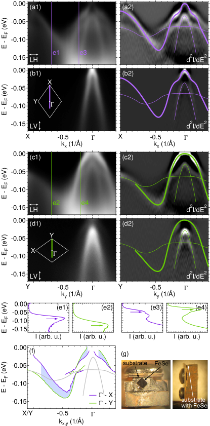
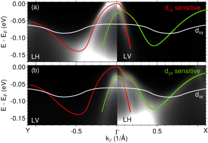
Figure 1 summarizes our ARPES results on detwinned FeSe. We identify three hole bands centered at , which we highlight with lines on top of the second derivative spectra Fig. 1(a2-d2). Signatures of hybridization become visible at points where they cross. In the following, we focus our analysis on the middle hole band marked with thick lines. It has character along the –X direction and character along –Y. They are intense in LH polarization and suppressed in LV polarization, consistent with the orbital character assignment. We extract their dispersion from minima in the second derivative of the energy distribution curves (EDCs) and plot them in Fig. 1(f). We find a binding energy difference along the two orthogonal momentum directions. This difference is a signature of the nematic order. We extract the momentum dependence of and plot it in Fig. 4(a). We only include momenta highlighted by the shaded area in Fig. 1(f). The band assignment in this momentum region agrees with existing literature Watson et al. (2015); Suzuki et al. (2015); Fanfarillo et al. (2016); Yi et al. . We disregard the region beyond , at which the band touches the band along –Y. Beyond this momentum close to the BZ corner, the band assignment and the resulting nematic band splitting is currently debated in literature due to this band crossing Yi et al. ; Fedorov et al. (2016); Watson et al. (2016); Zhang et al. (2016). For small momenta close to , the dispersion could not be determined reliably when the band is too close to or above . Our spectra in Fig. 1(a-d) confirm previous results on detwinned FeSe Suzuki et al. (2015). While Ref. Suzuki et al., 2015 focuses on the Fermi surface distortions, we extended this work by extracting the full momentum dependence of the nematic splitting.
The nematic band splitting leads to a redistribution of orbital character at . We show the spectra of FeSe in the ordered state arranged according to the orbital sensitivity of different light polarization in Fig. 2. We observe an increase of orbital character at the Fermi level around while the spectral weight is pushed below . Figure 2 also reveals a hybridization signature along –X close to . It is a consequence of spin-orbit coupling (SOC) and underlines the importance of this interaction for the understanding of the electronic structure in FeSC Fernandes and Vafek (2014); Borisenko et al. (2016); Day et al. (2018); Watson et al. (2015). We will describe its effect in detail below (Fig. 4).
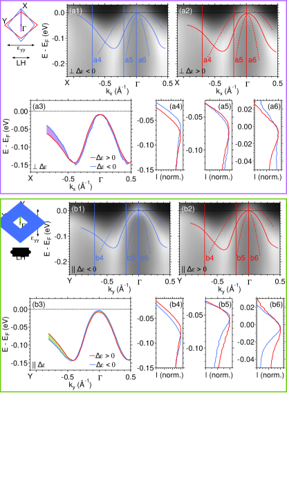
Our experimental observations on strained BaFe2As2 are presented in Fig. 3. In general, uniaxial pressure applied along one of the in-plane Fe-Fe bond directions or results in a symmetric strain and an antisymmetric strain (note that here the and axes are at to the tetragonal [100] and [010] directions) Palmstrom et al. (2017); Ikeda et al. (2018). The antisymmetric strain breaks the same symmetry as the nematic order and, hence, induces a nonzero value of the nematic order parameter at all temperatures. The associated nematic band splitting is given by the antisymmetric term , while the symmetric response is given by . Here, refers to the strain-induced change in binding energy.
Following this idea, we applied uniaxial pressure to one main in-plane axis, which we call without loss of generality (see Fig. 3(d)). ARPES measurements were performed along and , i.e. perpendicular (Fig. 3(a)) and parallel (Fig. 3(b)) to the direction of the applied pressure. For each momentum direction, we took a spectrum for a compressed () and a tensioned () state of the sample to extract the strain-induced . We will focus again on the middle hole band (solid line in Fig. 3(a1,a2,b1,b2)) and present spectra taken with LH polarization. The dispersion of the hole band is extracted from the maxima of the EDCs and plotted in Fig. 3(a3,b3). We can indeed observe a strain-induced change in the dispersion between the spectra taken with positive and negative pressure and extract the difference , which is plotted in Fig. 3(c). has a very similar functional form for both momentum directions but with opposite sign. The size of the symmetric signal is therefore very small and below 5 meV for all momenta. The nematic band splitting , i.e. the antisymmetric component, is shown in Fig. 4(b).
The spectra in Fig. 3 indicate a strain offset, i.e. 0 V on the piezoelectric stacks does not correspond to , likely due to different thermal expansion coefficients of the different materials. The offset does not affect our analysis of , because it only considers the relative strain and binding energy differences.
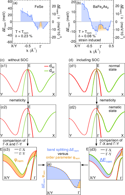
Figure 4(a,b) compares the results of the nematic band splitting for FeSe and BaFe2As2. has the same momentum dependence with a sign change between and the BZ corner. It has a value close to zero at . For FeSe, no values could be obtained close to as detailed earlier, but we expect at from the trend in the dispersions (Fig. 1).
Figures 4(c,d) sketch the changes of the band structure due to nematic order based on the observed . We illustrate the cases without (c) and with (d) SOC. From the case without SOC (Fig. 4(c3)), one can define a momentum-dependent nematic order parameter as the difference in binding energy between two orthogonal momentum directions. This definition naturally captures the -wave distortion of the Fermi surface that originates from the sign change of the order parameter between and . For the high-symmetry direction shown in Fig. 4(c3), our definition implies that is the difference between the binding energies along and along .
The comparison to Fig. 4(d) underlines the large effect of SOC on the band structure and the measured . Importantly, the experimentally determined quantity equals only away from where SOC does not affect the dispersion, see Fig. 4(e). In particular, the crossing of the and band close to along –X leads to a hybridization gap and while stays nonzero. However, from the comparison of and in Fig. 4(e) and from the functional form of in Fig. 4(a,b), we can conclude that the nematic order parameter has an additional sign change between the BZ center and the BZ corner close to . At this wave vector, is not altered by the effect of SOC that is described above. is approximately twice as large at the BZ corner compared to the BZ center. To determine the exact value at , SOC has to be taken into account. One expects a binding energy difference between the inner and middle hole band at of Fernandes and Vafek (2014), which is approximately 30 meV for FeSe determined from Fig. 1. Together with a SOC of meV Borisenko et al. (2016) we obtain meV in agreement with the results shown in Fig. 4(a).
We point out that the center hole band loses or character away from high-symmetry points of the BZ. However, they remain the majority orbital contribution Graser et al. (2010). Such orbital admixture can lead to modulations of . However, the sign change of between and the BZ corner is robust against these considerations because the bands have pure orbital character at the high-symmetry points and the band shift is therefore proportional to .
Given the different orthorhombic distortions in FeSe and BaFe2As2, we also compare the nematic susceptibility . From the lattice constants of FeSe inside the nematic state Horigane et al. (2009) we determine %. We estimate % for BaFe2As2 from the strain measurement, which is smaller than the orthorhombic lattice distortion of 0.39% inside the nematic phase Huang et al. (2008). Therefore, the magnitude of in BaFe2As2 will be larger inside the nematic phase compared to Fig. 4(b). The nematic susceptibility has the same order of magnitude in both compounds, demonstrating a similar strength of the nematic order. Small differences are expected: First, is temperature dependent Chu et al. (2012); Böhmer et al. (2014); Massat et al. (2016) and we compare measurements at different temperatures . Second, in different optimally doped FeSC, the nematic susceptibility has slightly different values Kuo et al. (2016).
Our experimental result demonstrates, that the nematic order parameter has the same momentum dependence in both FeSe and BaFe2As2 and could even be universal among the FeSCs. It suggests that the same microscopic mechanism drives nematicity despite the absence of magnetism in FeSe. A pure on-site ferro-orbital order can be excluded for both systems as it does not support a sign change in . A number of other models were proposed including bond-orbital order Su et al. (2015); Mukherjee et al. (2015); Li and Su (2017); Onari et al. (2016), a Pomeranchuk instability Chubukov et al. (2016), orbital-selective spin fluctuations Fanfarillo et al. (2016), frustrated magnetism Wang et al. (2015), and spin-driven Ising-nematic order Fernandes et al. (2010); Yu and Si (2015). Our result puts strong constraints on the theoretical description of the nematic order in FeSC.
In summary, we determined the momentum dependence of the nematic order parameter in FeSe and in BaFe2As2 using ARPES. To this end, we studied the nematic band splitting in detwinned FeSe inside the ordered phase. BaFe2As2 was studied above the magnetic ordering temperature and we induced a nematic band splitting in a controlled way by the application of uniaxial pressure. Despite the very different magnetic properties of both materials, the nematic order parameter exhibits the same momentum dependence with a sign change between the BZ center and the BZ corner. It will be very interesting to perform similar studies on other nematic FeSC to test if this is a universal behavior of the nematic order parameter.
Acknowledgements.
We are very grateful for valuable discussions with R. Fernendes, A. Kemper, Q. Si, Y. Zhang and C. Watson. H.P. acknowledges support from the Alexander von Humboldt Foundation and from the German Science Foundation (DFG) under reference PF 947/1-1. J.C.P. is supported by a Gabilan Stanford Graduate Fellowship and a NSF Graduate Research Fellowship (grant DGE-114747). J.S. acknowledges support from an ABB Stanford Graduate Fellowship. This work was supported by the Department of Energy, Office of Basic Energy Sciences, under Contract No. DE-AC02-76SF00515. The FeSe single crystal growth and characterization work at Rice was supported by the U.S. DOE, BES DE-SC0012311 and in part by the Robert A. Welch Foundation Grant No. C-1839 (P.-C.D.). Use of the Stanford Synchrotron Radiation Lightsource, SLAC National Accelerator Laboratory, is supported by the U.S. Department of Energy, Office of Science, Office of Basic Energy Sciences under Contract No. DE-AC02-76SF00515. Work at Lawrence Berkeley National Laboratory was funded by the U.S. Department of Energy, Office of Science, Office of Basic Energy Sciences, Materials Sciences and Engineering Division under Contract No. DE-AC02-05-CH11231 within the Quantum Materials Program (KC2202).References
- Ando et al. (2002) Y. Ando, K. Segawa, S. Komiya, and A. N. Lavrov, Phys. Rev. Lett. 88, 137005 (2002).
- Kasahara et al. (2006) Y. Kasahara, Y. Shimono, T. Shibauchi, Y. Matsuda, S. Yonezawa, Y. Muraoka, and Z. Hiroi, Phys. Rev. Lett. 96, 247004 (2006).
- Achkar et al. (2016) A. J. Achkar, M. Zwiebler, C. McMahon, F. He, R. Sutarto, I. Djianto, Z. Hao, M. J. P. Gingras, M. Hücker, G. D. Gu, A. Revcolevschi, H. Zhang, Y.-J. Kim, J. Geck, and D. G. Hawthorn, Science 351, 576 (2016).
- Ronning et al. (2017) F. Ronning, T. Helm, K. R. Shirer, M. D. Bachmann, L. Balicas, M. K. Chan, B. J. Ramshaw, R. D. McDonald, F. F. Balakirev, M. Jaime, E. D. Bauer, and P. J. W. Moll, Nature 548, 313 (2017).
- Paglione and Greene (2010) J. Paglione and R. L. Greene, Nat. Phys. 6, 645 (2010).
- Johnston (2010) D. C. Johnston, Adv. Phys. 59, 803 (2010).
- Kuo et al. (2016) H.-H. Kuo, J.-H. Chu, J. C. Palmstrom, S. A. Kivelson, and I. R. Fisher, Science 352, 958 (2016).
- Fernandes et al. (2014) R. M. Fernandes, A. V. Chubukov, and J. Schmalian, Nat. Phys. 10, 97 (2014).
- Baek et al. (2015) S.-H. Baek, D. V. Efremov, J. M. Ok, J. S. Kim, J. van den Brink, and B. Büchner, Nat. Mater. 14, 210 (2015).
- Böhmer et al. (2014) A. E. Böhmer, P. Burger, F. Hardy, T. Wolf, P. Schweiss, R. Fromknecht, M. Reinecker, W. Schranz, and C. Meingast, Phys. Rev. Lett. 112, 047001 (2014).
- Yi et al. (2017) M. Yi, Y. Zhang, Z.-X. Shen, and D. Lu, npj Quantum Materials 2, 57 (2017).
- McQueen et al. (2009) T. M. McQueen, A. J. Williams, P. W. Stephens, J. Tao, Y. Zhu, V. Ksenofontov, F. Casper, C. Felser, and R. J. Cava, Phys. Rev. Lett. 103, 057002 (2009).
- Zhang et al. (2016) Y. Zhang, M. Yi, Z.-K. Liu, W. Li, J. J. Lee, R. G. Moore, M. Hashimoto, M. Nakajima, H. Eisaki, S.-K. Mo, Z. Hussain, T. P. Devereaux, Z.-X. Shen, and D. H. Lu, Phys. Rev. B 94, 115153 (2016).
- Suzuki et al. (2015) Y. Suzuki, T. Shimojima, T. Sonobe, A. Nakamura, M. Sakano, H. Tsuji, J. Omachi, K. Yoshioka, M. Kuwata-Gonokami, T. Watashige, R. Kobayashi, S. Kasahara, T. Shibauchi, Y. Matsuda, Y. Yamakawa, H. Kontani, and K. Ishizaka, Phys. Rev. B 92, 205117 (2015).
- Kim et al. (2011a) M. G. Kim, R. M. Fernandes, A. Kreyssig, J. W. Kim, A. Thaler, S. L. Bud’ko, P. C. Canfield, R. J. McQueeney, J. Schmalian, and A. I. Goldman, Phys. Rev. B 83, 134522 (2011a).
- (16) D. Hsieh, Y. Xia, L. Wray, D. Qian, K. Gomes, A. Yazdani, G. F. Chen, J. L. Luo, N. L. Wang, and M. Z. Hasan, arXiv:0812.2289v1 .
- Yang et al. (2009) L. X. Yang, Y. Zhang, H. W. Ou, J. F. Zhao, D. W. Shen, B. Zhou, J. Wei, F. Chen, M. Xu, C. He, Y. Chen, Z. D. Wang, X. F. Wang, T. Wu, G. Wu, X. H. Chen, M. Arita, K. Shimada, M. Taniguchi, Z. Y. Lu, T. Xiang, and D. L. Feng, Phys. Rev. Lett. 102, 107002 (2009).
- Yi et al. (2009) M. Yi, D. H. Lu, J. G. Analytis, J.-H. Chu, S.-K. Mo, R.-H. He, M. Hashimoto, R. G. Moore, I. I. Mazin, D. J. Singh, Z. Hussain, I. R. Fisher, and Z.-X. Shen, Phys. Rev. B 80, 174510 (2009).
- Yi et al. (2011) M. Yi, D. Lu, J.-H. Chu, J. G. Analytis, A. P. Sorini, A. F. Kemper, B. Moritz, S.-K. Mo, R. G. Moore, M. Hashimoto, W.-S. Lee, Z. Hussain, T. P. Devereaux, I. R. Fisher, and Z.-X. Shen, Proc. Natl. Acad. Sci. U.S.A. 108, 6878 (2011).
- Kim et al. (2011b) Y. Kim, H. Oh, C. Kim, D. Song, W. Jung, B. Kim, H. J. Choi, C. Kim, B. Lee, S. Khim, H. Kim, K. Kim, J. Hong, and Y. Kwon, Phys. Rev. B 83, 064509 (2011b).
- Wang et al. (2013) Q. Wang, Z. Sun, E. Rotenberg, F. Ronning, E. D. Bauer, H. Lin, R. S. Markiewicz, M. Lindroos, B. Barbiellini, A. Bansil, and D. S. Dessau, Phys. Rev. B 88, 235125 (2013).
- Liu et al. (2009) G. Liu, H. Liu, L. Zhao, W. Zhang, X. Jia, J. Meng, X. Dong, J. Zhang, G. F. Chen, G. Wang, Y. Zhou, Y. Zhu, X. Wang, Z. Xu, C. Chen, and X. J. Zhou, Phys. Rev. B 80, 134519 (2009).
- Kondo et al. (2010) T. Kondo, R. M. Fernandes, R. Khasanov, C. Liu, A. D. Palczewski, N. Ni, M. Shi, A. Bostwick, E. Rotenberg, J. Schmalian, S. L. Bud’ko, P. C. Canfield, and A. Kaminski, Phys. Rev. B 81, 060507(R) (2010).
- Fuglsang Jensen et al. (2011) M. Fuglsang Jensen, V. Brouet, E. Papalazarou, A. Nicolaou, A. Taleb-Ibrahimi, P. Le Fèvre, F. Bertran, A. Forget, and D. Colson, Phys. Rev. B 84, 014509 (2011).
- Pfau et al. (2019) H. Pfau, C. R. Rotundu, J. C. Palmstrom, S. D. Chen, M. Hashimoto, D. Lu, A. F. Kemper, I. R. Fisher, and Z.-X. Shen, Phys. Rev. B 99, 035118 (2019).
- Richard et al. (2010) P. Richard, K. Nakayama, T. Sato, M. Neupane, Y.-M. Xu, J. H. Bowen, G. F. Chen, J. L. Luo, N. L. Wang, X. Dai, Z. Fang, H. Ding, and T. Takahashi, Phys. Rev. Lett. 104, 137001 (2010).
- Shimojima et al. (2010) T. Shimojima, K. Ishizaka, Y. Ishida, N. Katayama, K. Ohgushi, T. Kiss, M. Okawa, T. Togashi, X.-Y. Wang, C.-T. Chen, S. Watanabe, R. Kadota, T. Oguchi, A. Chainani, and S. Shin, Phys. Rev. Lett. 104, 057002 (2010).
- Kuo and Fisher (2014) H.-H. Kuo and I. R. Fisher, Phys. Rev. Lett. 112, 227001 (2014).
- Chu et al. (2009) J.-H. Chu, J. G. Analytis, C. Kucharczyk, and I. R. Fisher, Phys. Rev. B 79, 014506 (2009).
- Wang et al. (2009) X. F. Wang, T. Wu, G. Wu, H. Chen, Y. L. Xie, J. J. Ying, Y. J. Yan, R. H. Liu, and X. H. Chen, Phys. Rev. Lett. 102, 117005 (2009).
- Rotundu et al. (2010) C. R. Rotundu, B. Freelon, T. R. Forrest, S. D. Wilson, P. N. Valdivia, G. Pinuellas, A. Kim, J.-W. Kim, Z. Islam, E. Bourret-Courchesne, N. E. Phillips, and R. J. Birgeneau, Phys. Rev. B 82, 144525 (2010).
- Watson et al. (2015) M. D. Watson, T. K. Kim, A. A. Haghighirad, N. R. Davies, A. McCollam, A. Narayanan, S. F. Blake, Y. L. Chen, S. Ghannadzadeh, A. J. Schofield, M. Hoesch, C. Meingast, T. Wolf, and A. I. Coldea, Phys. Rev. B 91, 155106 (2015).
- Brouet et al. (2009) V. Brouet, M. Marsi, B. Mansart, A. Nicolaou, A. Taleb-Ibrahimi, P. Le Fèvre, F. Bertran, F. Rullier-Albenque, A. Forget, and D. Colson, Phys. Rev. B 80, 165115 (2009).
- Zhang et al. (2011) Y. Zhang, F. Chen, C. He, B. Zhou, B. P. Xie, C. Fang, W. F. Tsai, X. H. Chen, H. Hayashi, J. Jiang, H. Iwasawa, K. Shimada, H. Namatame, M. Taniguchi, J. P. Hu, and D. L. Feng, Phys. Rev. B 83, 054510 (2011).
- Brouet et al. (2012) V. Brouet, M. F. Jensen, P.-H. Lin, A. Taleb-Ibrahimi, P. Le Fèvre, F. Bertran, C.-H. Lin, W. Ku, A. Forget, and D. Colson, Phys. Rev. B 86, 075123 (2012).
- Chen et al. (2019) T. Chen, Y. Chen, A. Kreisel, X. Lu, A. Schneidewind, Y. Qiu, J. T. Park, T. G. Perring, J. R. Stewart, H. Cao, R. Zhang, Y. Li, Y. Rong, Y. Wei, B. M. Andersen, P. J. Hirschfeld, C. Broholm, and P. Dai, Nature Materials 18, 709 (2019).
- Hicks et al. (2014) C. W. Hicks, M. E. Barber, S. D. Edkins, D. O. Brodsky, and A. P. Mackenzie, Rev. Sci. Instrum. 85, 065003 (2014).
- Riccò et al. (2018) S. Riccò, M. Kim, A. Tamai, S. McKeown Walker, F. Y. Bruno, I. Cucchi, E. Cappelli, C. Besnard, T. K. Kim, P. Dudin, M. Hoesch, M. J. Gutmann, A. Georges, R. S. Perry, and F. Baumberger, Nature Communications 9, 4535 (2018).
- Flötotto et al. (2018) D. Flötotto, Y. Bai, Y.-H. Chan, P. Chen, X. Wang, P. Rossi, C.-Z. Xu, C. Zhang, J. A. Hlevyack, J. D. Denlinger, H. Hong, M.-Y. Chou, E. J. Mittemeijer, J. N. Eckstein, and T.-C. Chiang, Nano Lett. 18, 5628 (2018).
- Fanfarillo et al. (2016) L. Fanfarillo, J. Mansart, P. Toulemonde, H. Cercellier, P. Le Fèvre, F. m. c. Bertran, B. Valenzuela, L. Benfatto, and V. Brouet, Phys. Rev. B 94, 155138 (2016).
- (41) M. Yi, Y. Zhang, H. Pfau, T. Chen, Z. Ye, M. Hashimoto, R. Yu, Q. Si, D.-H. Lee, P. Dai, Z. X. Shen, D. Lu, and R. J. Birgeneau, arXiv:1903.04557v1 .
- Fedorov et al. (2016) A. Fedorov, A. Yaresko, T. K. Kim, Y. Kushnirenko, E. Haubold, T. Wolf, M. Hoesch, A. Grüneis, B. Büchner, and S. V. Borisenko, Sci. Rep. 6, 36834 (2016).
- Watson et al. (2016) M. D. Watson, T. K. Kim, L. C. Rhodes, M. Eschrig, M. Hoesch, A. A. Haghighirad, and A. I. Coldea, Phys. Rev. B 94, 201107(R) (2016).
- Fernandes and Vafek (2014) R. M. Fernandes and O. Vafek, Phys. Rev. B 90, 214514 (2014).
- Borisenko et al. (2016) S. V. Borisenko, D. V. Evtushinsky, Z.-H. Liu, I. Morozov, R. Kappenberger, S. Wurmehl, B. Buchner, A. N. Yaresko, T. K. Kim, M. Hoesch, T. Wolf, and N. D. Zhigadlo, Nat Phys 12, 311 (2016).
- Day et al. (2018) R. P. Day, G. Levy, M. Michiardi, B. Zwartsenberg, M. Zonno, F. Ji, E. Razzoli, F. Boschini, S. Chi, R. Liang, P. K. Das, I. Vobornik, J. Fujii, W. N. Hardy, D. A. Bonn, I. S. Elfimov, and A. Damascelli, Phys. Rev. Lett. 121, 076401 (2018).
- Palmstrom et al. (2017) J. C. Palmstrom, A. T. Hristov, S. A. Kivelson, J.-H. Chu, and I. R. Fisher, Phys. Rev. B 96, 205133 (2017).
- Ikeda et al. (2018) M. S. Ikeda, T. Worasaran, J. C. Palmstrom, J. A. W. Straquadine, P. Walmsley, and I. R. Fisher, Phys. Rev. B 98, 245133 (2018).
- Graser et al. (2010) S. Graser, A. F. Kemper, T. A. Maier, H.-P. Cheng, P. J. Hirschfeld, and D. J. Scalapino, Phys. Rev. B 81, 214503 (2010).
- Horigane et al. (2009) K. Horigane, H. Hiraka, and K. Ohoyama, J. Phys. Soc. Jpn. 78, 074718 (2009).
- Huang et al. (2008) Q. Huang, Y. Qiu, W. Bao, M. A. Green, J. W. Lynn, Y. C. Gasparovic, T. Wu, G. Wu, and X. H. Chen, Phys. Rev. Lett. 101, 257003 (2008).
- Chu et al. (2012) J.-H. Chu, H.-H. Kuo, J. G. Analytis, and I. R. Fisher, Science 337, 710 (2012).
- Massat et al. (2016) P. Massat, D. Farina, I. Paul, S. Karlsson, P. Strobel, P. Toulemonde, M.-A. Méasson, M. Cazayous, A. Sacuto, S. Kasahara, T. Shibauchi, Y. Matsuda, and Y. Gallais, Proc. Natl. Acad. Sci. U.S.A. 113, 9177 (2016).
- Su et al. (2015) Y. Su, H. Liao, and T. Li, J. Phys.: Condens. Matter 27, 105702 (2015).
- Mukherjee et al. (2015) S. Mukherjee, A. Kreisel, P. J. Hirschfeld, and B. M. Andersen, Phys. Rev. Lett. 115, 026402 (2015).
- Li and Su (2017) T. Li and Y. Su, J. Phys.: Condens. Matter 29, 425603 (2017).
- Onari et al. (2016) S. Onari, Y. Yamakawa, and H. Kontani, Phys. Rev. Lett. 116, 227001 (2016).
- Chubukov et al. (2016) A. V. Chubukov, M. Khodas, and R. M. Fernandes, Phys. Rev. X 6, 041045 (2016).
- Wang et al. (2015) F. Wang, S. A. Kivelson, and D.-H. Lee, Nat. Phys. 11, 959 (2015).
- Fernandes et al. (2010) R. M. Fernandes, L. H. VanBebber, S. Bhattacharya, P. Chandra, V. Keppens, D. Mandrus, M. A. McGuire, B. C. Sales, A. S. Sefat, and J. Schmalian, Phys. Rev. Lett. 105, 157003 (2010).
- Yu and Si (2015) R. Yu and Q. Si, Phys. Rev. Lett. 115, 116401 (2015).