Tuning superparamagnetism in perpendicular magnetic tunnel junctions
Abstract
Thin electrodes of magnetic tunnel junctions can show superparamagnetism at surprisingly low temperature. We analysed their thermally induced switching for varying temperature, magnetic and electric field. Although the dwell times follow an Arrhenius law, they are orders of magnitude too small compared to a model of single domain activation. Including entropic effects removes this inconsistency and leads to a magnetic activation volume much smaller than that of the electrode. Comparing data for varying barrier thickness then allows to separate the impact of Zeman energy, spin-transfer-torque and voltage induced anisotropy change on the dwell times. Based on these results, we demonstrate a tuning of the switching rates by combining magnetic and electric fields, which opens a path for their application in noisy neural networks.
Magnetic tunnel junctions (MTJs) with magnetically perpendicular CoFeB electrodes Ikeda.2010 are key components for hard disk read heads Maat.2016 and low power nonvolatile memories Wang.2013 . For such MTJs with CoFeB electrodes thinner than about , an unexpectedly low critical current density for spin-transfer-torque switching in the range of has been found Leutenantsmeyer.2015 , and recent reports demonstrated a superparamagnetic behavior Parks.2018 ; Carboni.2019 , i.e. a thermally activated switching of the magnetic electrode that depends on the size, the temperature and a variety of external parameters. The observed switching rates, however, are not compatible with a magnetic single-domain behavior of the electrode, because the energy barrier for magnetization reversal would be by orders of magnitude too large. A granular structure of the CoFeB has been discussed Tsai.2014 , but there is no unambiguous explanation up to now.
Such superparamagnetic MTJs (sp-MTJs) can serve to study superparamagnetism life and be useful for applications. Recently, we proposed a true random number generator based on sp-MTJs Reiss.2018 . Moreover, they can serve in noisy neural-like computing. One precondition is a pronounced maximum of the sp-MTJ’s thermal switching rate in dependence of an external input and a shift of these tuning curves by another external parameter. Mizrahi et al. Mizrahi.2018 ; Mizrahi.2018b demonstrated this by varying the current through sp-MTJs.
We investigated magnetically perpendicular sp-MTJs with an exchange biased reference CoFeB electrode Manos.2019 , an MgO barrier and a thick free CoFeB electrode. The film stacks were deposited by dc and rf sputtering on a Si/SiO2(50) substrate. The layer sequence was Ta(5)/ Ru(30)/ Ta(10)/ Pd(2)/ MnIr(8)/ CoFe(1)/ Ta(0.4)/ Co4Fe4B2(0.8)/ MgO(X)/ Co4Fe4B2(1.1)/ Ta(3)/ Ru(3) (units in ), and the thickness X of the MgO was , or . To set the exchange bias and to crystallize the CoFeB/MgO/CoFeB, the samples were annealed at for in a perpendicular magnetic field of . The films were patterned into circular pillars with a nominal diameter of and contacted via Au contacts by electron beam lithography. The overlap between the upper and lower contact was kept as small as possible to reduce the capacitive coupling and to enable a detection of the current through the MTJ at high frequency.
First, we analyzed the plane films’ quasistatic magnetic properties (see supplement appendix A), which means that the typical time needed for one data point is . When an external field is applied in-plane at room temperature, the free CoFeB layer shows an anisotropy field . The coercive field measured with an out-of-plane external field, however, is much smaller than and decreases strongly with temperature. Similar properties are found for the quasistatic tunneling magnetoresistance minor loops of the patterned MTJs. For the example discussed in the supplement, is around at and reaches zero at . The magnetic properties of our film systems and MTJs thus are similar as reported by, e.g., Zhu et al. Zhu.2012 . To elucidate this puzzling switching behavior, we analyzed the time dependence of the current through MTJs with diameter under varying temperature, magnetic and electric field.
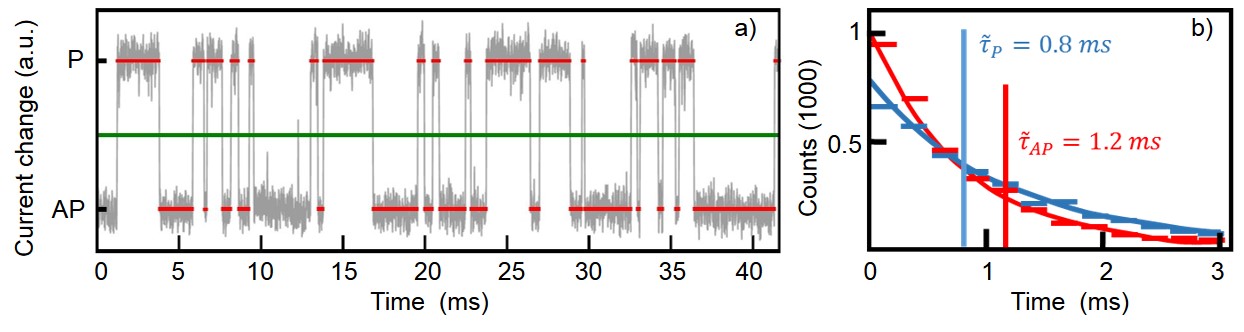
From the typical example shown in figure 1 a) it becomes clear, that the MTJ is in a superparamagnetic state with a switching time in the ms-range at . The distributions of dwell times taken from data as that of figure 1 a) follow an exponential law as shown in figure 1 b) with the with mean dwell times . This property of the MTJs has severe consequences, because extrinsic quantities such as that are evaluated from quasistatic measurements will depend on the time scale, at which data are taken. If we, e.g., take a magnetic hysteresis loop with an out-of-plane external magnetic field at a typical measurement time much larger than , the apparent will be zero, whereas non-zero values will be found otherwise. Nevertheless, the system maintains its pronounced out-of-plane anisotropy and switches only between the parallel and the antiparallel state with mean dwell times . Thus the (intrinsic) anisotropy field evaluated from quasistatic characterization is still valid.
To obtain quantitative data for the superparamagnetic state of our MTJs, we have to discuss briefly the statistics of the dwell times. With perpendicular magnetic anisotropy and in a single domain approach, an Arrhenius law describes the mean dwell time in the Neél-Brown model Petracic.2010 ; Brown.1963 : . is the energy barrier depending on the magnetic and electric field and , the Boltzmann constant. is the attempt time, which is the inverse of the ferromagnetic resonance frequency Wild.2017 . For ferromagnetic out-of-plane systems the attempt time at zero external field is of the order of Beaujour.2009 . In real superparamagnetic systems with possibly granular substructure Tsai.2014 , however, the entropy will play a significant role, because the system has plenty of possible pathways for magnetization switching. Using the free energy results in Wild.2017 :
| (1) |
To correspondingly analyze the behavior in more detail, we thus have three handles: the temperature T, the magnetic and the electric field.
If we apply a magnetic field perpendicular to the film plane, the Zeman energy (: magnetic vacuum permeability) will prefer an alignement of the magnetization and and thus change the mean dwell times correspondingly. is either the electrode’s volume Fruchart.1999 ; Kirilyuk.1997 or in case of granularity the magnetic activation volume Kirby.2000 . The dependence of the energy barrier in equation 1 on in absence of spin torque is then given by . In figure 2, we show exemplarily the dwell times as a function of the perpendicular magnetic field for an MTJ with MgO thickness at different temperatures.
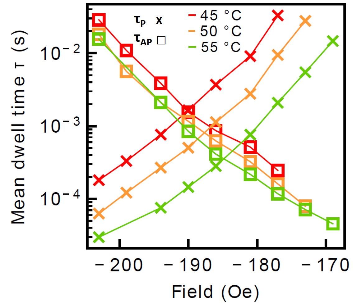
Since the pinned and the free magnetic electrode are ferromatically coupled due to their magnetic stray field, and are equal at an external field that compensates the coupling and adds an energy of to the basic energy barrier (K: effective anisotropy). We thus evaluated the data by shifting the field axis to . With this and the collinearity of and , are given by:
| (2) |
The energy barrier and the product can be determined from taking the derivative of with respect to or , respectively. The results of this evaluation are summarized in table 1.
| 1.2 | 9,28 | 2.5 | 26 | 12.7 | 1022 |
| 1.4 | 8,33 | 1.3 | 13,5 | 24,3 | 918 |
| 1.6 | 6,29 | 2.4 | 24,9 | 13,2 | 693 |
If we compare the measured effective anisotropy () with the apparent value deduced from , there is a large discrepancy ranging from to with a mean value of . Taking, however, granularity of the electrode into account, then the magnetic activation volume is correspondingly smaller. With a radius of the electrode of , the radius of the activation volume is nm . One test of this model is the resulting saturation magnetization , which was reported to be between between and Tsai.2014 ; Manos.2019 depending on the preparation conditions and if dead magnetic layers at the interfaces are considered or not. Using the full electrode’s volume, we obtain from in table 1 an smaller than , i.e. unphysically low values. Using the determined magnetic activation volume , the resulting values for (see table 1) are in agreement with the literature. Moreover, the lateral size of is very well comparable to the typical domain wall width found for similar CoFeB films with perpendicular magnetic anisotropy Yamanouchi.2011 , and about twice the value of the typical lateral grain size in our samples (see supplement appendix C). Thus modelling the properties with this activation volume leads to physical consistency.
Using these results, we can now estimate, how much entropic effects impact the dwell times. The effect of the entropy can be evaluated for and small bias voltage from the intercept when plotting versus . This gives values for of the order of 35, which means that is of the order of ! This number seems to be extraordinarily large. Similar values have, however, already been found for the decay of skyrmionic magnetization patterns Wild.2017 and their magnitude was related with the vast amount of pathes for skyrmion decay. For our MTJs, we can again estimate the magnetic activation volume from the number w of the entropic pathways that can lead to their thermally activated magnetization switching. If we assume, that the switching can start at either of N sub-volumes of the free electrode, then we have around possible pathes. Thus resulting in for our sp-MTJs with radius. The radius of a single activation volume is then . It is remarkable, that the two approaches to evaluate lead to almost the same radii, although the underlying physics is in the first case the evaluation of the energetics of the switching process, while thermodynamic considerations are used in the second.
We now turn to the influence of the bias voltage on the switching process and the dwell time. If a bias voltage is applied to the MTJ, two additional effects act on the magnetization: first, the spin torque due to the spin polarization of the current with the MTJ’s contact resistance and the inverse decay length B. Second, the electric field at the interfaces modifies the interfacial magnetic anisotropy energy density Weisheit.2007 ; Kanai.2012 ; Wang.2011 and leads to a linear change of the anisotropy with Endo.2010 ; Niranjan.2010 ; Shiota.2011 : , where characterizes the strength of the dependence of on . Spin torque and anisotropy change, however, have fundamentally different impact on : While spin torque will stabilize one of the (P, AP) states and destabilize the other one, the anisotropy change will either de- or increase both and , depending on the polarity of . In addition, for fixed , the influence of the spin torque on the magnetization decreases exponentially with increasing MgO barrier thickness. In contrast, the anisotropy change decreases only with . Thus for thin barriers, the spin torque can be expected to be dominant, while for thick barriers the change of the anisotropy can have larger impact.
At fixed , the dependence of on the bias voltage is taken into account by multiplying equation 2 with the factor , where and describe the strength of the anisotropy change and the spin torque, respectively. By convention, we use the plus sign for the P- and the minus sign for the AP-state. Then, the influences of the anisotropy change and the spin torque can be separated by evaluating
| (3) |
where gives the anisotropy change and the spin torque influence (see section Data evaluation).
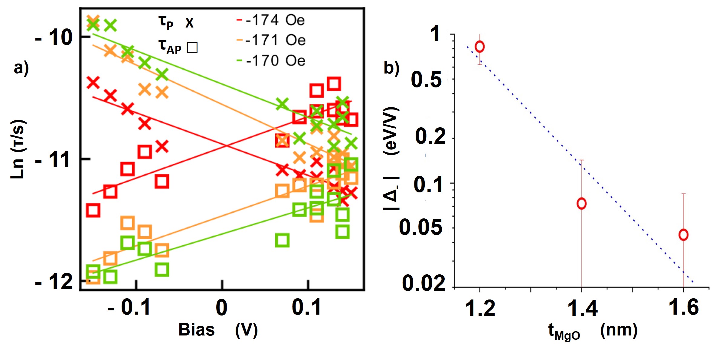
In figure 3 a), we show the results for the dwell times as a function of for at , and in b) the results of fitting the spin torque part as a function of with an exponential function. As expected, the spin torque term is for barrier thickness with more than four times larger than that of the anisotropy change ( ), while for this ratio reduces to two ( and ). The numerical evaluation of the data for the three MgO thicknesses gives a spin torque term , which mirrors the exponential dependence of the current density on . The anisotropy contribution results in . The separation of the small anisotropy contribution from the spin torque term is, however, not very reliable. The value obtained here is, however, very similar to the result of obtained by Endo et al. for MgO/CoFeB/Ta thin films Endo.2010 , which corresponds to the free layer system used in our MTJs.
Now, we can combine the impacts of the magnetic field and the electric field to realize tuning curves. If an sp-MTJ is only either in the P or the AP state such as the 140nm diameter devices used in this work, the tuning curve is given by the switching frequency . If the barrier thickness is too large, the application of would change only the anisotropy. This would give a simultaneous de- or increase of both dwell times and thus tuning of the switching rates, i.e. a shift of the gaussian dependence on one parameter by the other one would not be possible. If, however, spin torque is dominating the impact of , one of the dwell times is driven exponentially to zero and the other one to infinity by application of either (figure 2), or (figure 3). In the corresponding range of barrier thickness, we can, therefore, use the combination of both to shift the dependence of the switching rate on one parameter by varying the other one.
The switching rate was evaluated exemplarily for the sample with thick MgO barrier in dependence of the two input parameters bias voltage and magnetic field. The switching frequency tuning curves as well as Gaussian fits are shown in figure 4 for constant magnetic field depending on the bias voltage (figure 4 a)) and for constant bias voltage depending on the magnetic field (figure 4 b)).
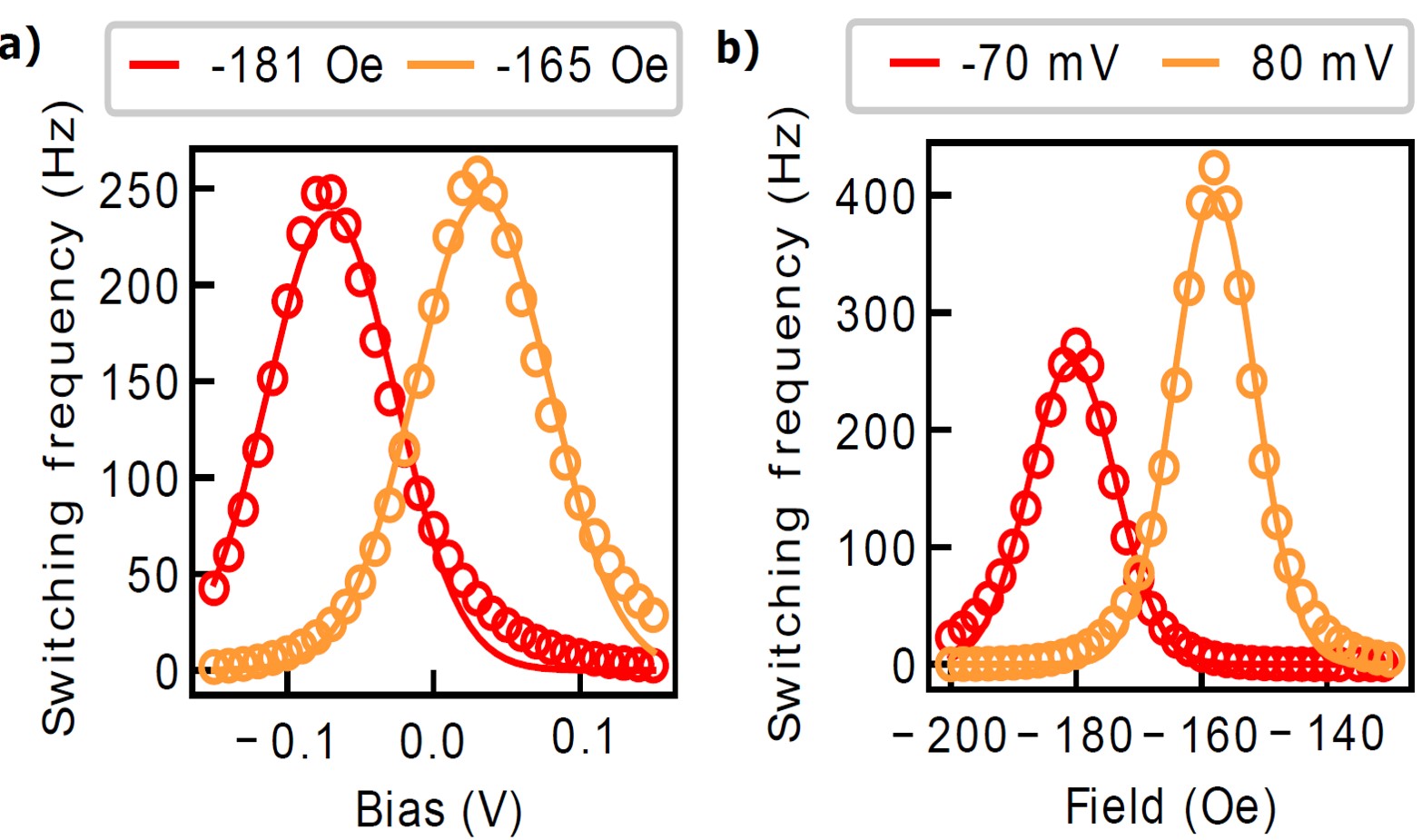
The results in figure 4 are in agreement with our finding, that spin torque dominates the impact of for a the thick tunneling barrier. The position of the peak for one input parameter can be easily shifted by varying the other one. The asymmetry in figure 4 b) comes from the change of the anisotropy, which de- or increases the switching rates depending on the sign of the applied voltage .
The tuning curves can be very well described with a Gaussian dependence on both input parameters and :
| (4) |
where is either the magnetic field or the bias voltage, is the peak position and the full width at half maximum.
For, e.g., figure 4 b, we find , and , for for and for , respectively. This tuning of the switching rates matches exactly the requirements for the firing rates of neurons in population coding networks Salinas.1995 and thus can emulate tuning curves for noisy neural-like computingMizrahi.2018 ; Pouget.2000 ; Mizrahi.2018b .
Acknowledgements.
The authors gratefully acknowledge the support of the work by the Deutsche Forschungsgemeinschaft under contract RE 1052/22-1 and -2. We also thank Hans-Werner Schumacher (PTB Braunschweig) for Kerr-microscopy.References
- [1] S. Ikeda, K. Miura, H. Yamamoto, K. Mizunuma, H. D. Gan, M. Endo, S. Kanai, J. Hayakawa, F. Matsukura, and H. Ohno. A perpendicular-anisotropy CoFeB-MgO magnetic tunnel junction. Nature materials, 9(9):721–724, 2010.
- [2] Stefan Maat and Arley C. Marley. Physics and design of hard disk drive magnetic recording read heads. In Yongbing Xu, David D. Awschalom, and Junsaku Nitta, editors, Handbook of Spintronics, pages 977–1028. Springer Netherlands, Dordrecht, 2016.
- [3] K. L. Wang, J. G. Alzate, and P. Khalili Amiri. Low-power non-volatile spintronic memory: Stt-ram and beyond. Journal of Physics D: Applied Physics, 46(7):074003, 2013.
- [4] Johannes Christian Leutenantsmeyer, Vladyslav Zbarsky, Marvin von der Ehe, Steffen Wittrock, Patrick Peretzki, Henning Schuhmann, Andy Thomas, Karsten Rott, Guenter Reiss, nter, Tae Hee Kim, Michael Seibt, Mü, and Markus nzenberg. Spin-transfer torque switching at ultra low current densities. Materials Transactions, 56(9):1323–1326, 2015.
- [5] Bradley Parks, Mukund Bapna, Julianne Igbokwe, Hamid Almasi, Weigang Wang, and Sara A. Majetich. Superparamagnetic perpendicular magnetic tunnel junctions for true random number generators. AIP Advances, 8(5):055903, 2018.
- [6] Roberto Carboni, Wei Chen, Manzar Siddik, Jon Harms, Andy Lyle, Witold Kula, Gurtej Sandhu, and Daniele Telmini. Random number generation by differential read of stochastic switching in spin-transfer torque memory. IEEE Electron Device Letters, 39(7):951–954, 2019.
- [7] C.C Tsai, Chih-Wei Cheng, Meng-Chiau Tsai, and G. Chern. Superparamagnetic states and perpendicular magnetic anisotropy in ultrathin MgO/CoFeB/ta structures. IEEE Transactions of Magnetics, 50(1):1401404, 2014.
- [8] Guenter Reiss and Karsten Rott. Apparatus, ic and system for generating real random numbers: Euopean patent submission ep17190931.
- [9] Alice Mizrahi, Julie Grollier, Damien Querlioz, and M. D. Stiles. Overcoming device unreliability with continuous learning in a population coding based computing system. Journal of Applied Physics, 124(15):152111, 2018.
- [10] Alice Mizrahi, Tifenn Hirtzlin, Akio Fukushima, Hitoshi Kubota, Shinji Yuasa, Julie Grollier, and Damien Querlioz. Neural-like computing with populations of superparamagnetic basis functions. Nature communications, 9(1):1533, 2018.
- [11] O. Manos, P. Bougiatioti, D. Dyck, T. Huebner, K. Rott, J.-M. Schmalhorst, and G. Reiss. Correlation of tunnel magnetoresistance with the magnetic properties in perpendicular CoFeB-based junctions with exchange bias. Journal of Applied Physics, 125:023905, 2019.
- [12] T. Zhu, Y. Yang, R.C. Yu, H. Ambaye, V. Lauter, and J.Q. Xiao. The study of perpendicular magnetic anisotropy in CoFeB sandwiched by MgO and tantalum layers using polarized neutron reflectometry. Applied Physics Letters, 100(20):202406, 2012.
- [13] O. Petracic. Superparamagnetic nanoparticle ensembles. Superlattices and Microstructures, 47(5):569–578, 2010.
- [14] William Fuller Brown. Thermal fluctuations of a single-domain particle. Physical Review, 130(5):1677–1686, 1963.
- [15] Johannes Wild, Thomas N. G. Meier, Simon Pöllath, Matthias Kronseder, Andreas Bauer, Alfonso Chacon, Marco Halder, Marco Schowalter, Andreas Rosenauer, Josef Zweck, Jan Müller, Achim Rosch, Christian Pfleiderer, and Christian H. Back. Entropy-limited topological protection of skyrmions. Science advances, 3(9):e1701704, 2017.
- [16] J.-M. Beaujour, D. Ravelosona, I. Tudosa, E.E. Fullerton, and A.D. Kent. Ferromagnetic resonance linewidth in ultrathin films with perpendicular magnetic anisotropy. Physical Review B, 80(180415(4)), 2009.
- [17] O. Fruchart, J.-P. Nozières, W. Wernsdorfer, D. Givord, F. Rousseaux, and D. Decanini. Enhanced coercivity in submicrometer-sized ultrathin epitaxial dots with in-plane magnetization. Physical Review Letters, 82(6):1305–1308, 1999.
- [18] A. Kirilyuk, J. Ferré, V. Grolier, J. P. Jamet, and D. Renard. Magnetization reversal in ultrathin ferromagnetic films with perpendicular anisotropy. Journal of Magnetism and Magnetic Materials, 171(1-2):45–63, 1997.
- [19] R. D. Kirby, M. Yu, and D. J. Sellmyer. Activation volumes in thin film and particulate systems. Journal of Applied Physics, 87:5696, 2000.
- [20] M. Yamanouchi, A. Jander, P. Dhagat, S. Ikeda, F. Matsukura, and H. Ohno. Domain structure in CoFeB thin films with perpendicular magnetic anisotropy. IEEE Magnetics Letters, 2:3000304, 2011.
- [21] Martin Weisheit, Sebastian Fähler, Alain Marty, Yves Souche, Christiane Poinsignon, and Dominique Givord. Electric field-induced modification of magnetism in thin-film ferromagnets. Science (New York, N.Y.), 315(5810):349–351, 2007.
- [22] S. Kanai, M. Yamanouchi, S. Ikeda, Y. Nakatani, F. Matsukura, and H. Ohno. Electric field-induced magnetization reversal in a perpendicular-anisotropy CoFeB-MgO magnetic tunnel junction. Applied Physics Letters, 101(12):122403, 2012.
- [23] Wei-Gang Wang, Mingen Li, Stephen Hageman, and C. L. Chien. Electric-field-assisted switching in magnetic tunnel junctions. Nature materials, 11(1):64–68, 2011.
- [24] M. Endo, S. Kanai, S. Ikeda, F. Matsukura, and H. Ohno. Electric-field effects on thickness dependent magnetic anisotropy of sputtered MgO/co40fe40b20/ta structures. Applied Physics Letters, 96(21):212503, 2010.
- [25] Manish K. Niranjan, Chun-Gang Duan, Sitaram S. Jaswal, and Evgeny Y. Tsymbal. Electric field effect on magnetization at the fe/MgO(001) interface. Applied Physics Letters, 96(22):222504, 2010.
- [26] Yoichi Shiota, Shinichi Murakami, Frédéric Bonell, Takayuki Nozaki, Teruya Shinjo, and Yoshishige Suzuki. Quantitative evaluation of voltage-induced magnetic anisotropy change by magnetoresistance measurement. Applied Physics Express, 4(4):43005, 2011.
- [27] E. Salinas and L. F. Abbott. Transfer of coded information from sensory to motor networks. The Journal of Neuroscience, 15(10):6461–6474, 1995.
- [28] Alexandre Pouget, Peter Dayan, and Richard Zemel. Information processing with population codes. Nature Reviews Neuroscience, 1(2):125, 2000.