Spin dynamics investigations for the EDM experiment at COSY
Abstract
Precision experiments, such as the search for a deuteron electric dipole moments using a storage rings like COSY, demand for an understanding of the spin dynamics with unprecedented accuracy. In such an enterprise, numerical predictions play a crucial role for the development and later application of spin-tracking algorithms. Various measurement concepts involving polarization effects induced by an RF Wien filter and static solenoids in COSY are discussed. The matrix formalism, applied here, deals solely with spin rotations on the closed orbit of the machine, and is intended to provide numerical guidance for the development of beam and spin-tracking codes for rings that employ realistic descriptions of the electric and magnetic bending and focusing elements, solenoids etc., and a realistically-modeled RF Wien filter.
pacs:
13.40.Em, 11.30.Er, 29.20.Dh, 29.27.HjI Introduction
The Standard Model (SM) of Particle Physics is not capable to account for the apparent matter-antimatter asymmetry of the Universe. Physics beyond the SM is required and it is either probed by employing high energies (e.g., at LHC), or by striving for ultimate precision and sensitivity (e.g., in the search for electric dipole moments). Permanent electric dipole moments (EDMs) of particles violate both time reversal and parity invariance, and are via the -theorem also -violating. Finding an EDM would be a strong indication for physics beyond the SM, and pushing upper limits further provides crucial tests for any corresponding theoretical model, e.g., SUSY.
Up to now, EDM searches mostly focused on neutral systems (neutrons, atoms, and molecules). Storage rings, however, offer the possibility to measure EDMs of charged particles by observing the influence of the EDM on the spin motion in the ring. These direct searches of e.g., proton and deuteron EDMs bear the potential to reach sensitivities beyond . Since the Cooler Synchrotron COSY111The synchrotron and storage ring COSY accelerates and stores unpolarized and polarized proton or deuteron beams in the momentum range of 0.3 to Weidemann et al. (2015). at the Forschungszentrum Jülich provides polarized protons and deuterons up to momenta of 3.7 GeV/c, it constitutes an ideal testing ground and a starting point for such an experimental program.
The investigations presented here, carried out in the framework of the JEDI Collaboration222Jülich Electric Dipole moment Investigations jed ., are relevant for the preparation of the deuteron EDM measurement Rathmann and Nikolaev (2019). A radio-frequency (RF) Wien filter (WF) Slim et al. (2016, 2017a, 2017b) makes it possible to carry out EDM measurements in a conventional magnetic machine like COSY. The idea is to look for an EDM-driven resonant rotation of the deuteron spins from the horizontal to vertical direction and vice versa, generated by the RF Wien filter at the spin precession frequency. The RF Wien filter per se is transparent to the EDM of the particles, its net effect is a frequency modulation of the spin tune, the number of spin precessions per turn. This modulation couples to the EDM precession in the static motional electric field of the ring, and generates an EDM-driven up-down oscillation of the beam polarization Morse et al. (2013).
The search for EDMs of protons, deuterons, and heavier nuclei using storage rings srE ; jed is part of an extensive world-wide effort to push further the frontiers of precision spin dynamics of polarized particles in storage rings. In this context, the JEDI results prompted the formation of the new CPEDM collaboration333Charged Particle Electric Dipole Moment Collaboration, http://pbc.web.cern.ch/edm/edm-default.htm, which aims at the development of a purely electric prototype storage ring, with drastically enhanced sensitivities to the EDM of protons and deuterons, compared to what is presently feasible at COSY Abusaif et al. (2018); Rathmann and Nikolaev (2019).
Precision experiments, such as the EDM searches, demand for an understanding of the spin dynamics with unprecedented accuracy, keeping in mind that the ultimate aim is to measure EDMs with a sensitivity up to 15 orders in magnitude better than the magnetic dipole moment (MDM) of the stored particles.
The description of the physics of the applied approach, called RF Wien filter mapping, is discussed further in a forthcoming separate publication. The theoretical understanding of the method and its experimental exploitation are prerequisites for the planned EDM experiments at COSY jed , and will also have an impact on the design of future dedicated EDM storage rings Abusaif et al. (2018).
This paper discusses various polarization effects that are induced by the RF Wien filter and static solenoids in the ring. The approach taken here strongly simplifies the machine lattice, and deals solely with spin rotations on the closed orbit Lee (1997); Mane et al. (2005), described by the formalism. One aim of the work is to obtain a basic understanding about the interplay of spin rotations in a magnetic ring equipped with an RF Wien filter and solenoid magnets, under the simplifying assumption mentioned above. In an ideal machine with perfect alignment of the magnetic elements, the spin rotations on the closed orbit are generated primarily by the dipole magnets, therefore, for the time being, spin rotations in the quadrupole magnets are not considered.
As we shall demonstrate below, even with an idealized ring, the parametric RF resonance-driven spin rotations reveal quite a reach pattern of spin dynamics. Our results set the background for more realistic spin tracking calculations, based on recent geodetic surveys of COSY that make available position offsets, roll, and inclination parameters for the quadrupole and dipole magnets. The treatment of the spin transport through these individually misaligned magnetic elements, can, however, be readily incorporated in the applied matrix formalism. Besides that, the spin dynamics simulations carried out in the framework of the present paper, will serve as a valuable crosscheck of the analytic approximate treatment of the parametric spin resonance, based on the Bogolyubov-Krylov-Mitropolsky averaging technique Bogoliubov and Mitropolsky (1961).
The JEDI collaboration is presently implementing a beam-based alignment scheme at COSY, which aims at providing optimized beam-transfer properties of the quadrupole and dipole magnets in the ring, with the aim to make the beam orbit as planar as possible Wagner (2019). Once this is accomplished, the spin dynamics in the ring will be largely governed by the misaligned dipoles alone. Thus effectively, the approach described here will appropriately describe an EDM experiment using an RF Wien filter in a beam-based aligned ring.
The paper is organized as follows. In Sec. II, the effect of an EDM on the spin-evolution in a ring is discussed in terms of the Thomas-BMT equation. The inclusion of an RF Wien filter in an otherwise ideal ring is treated in Sec. III, while the polarization evolution with an RF Wien filter and additional solenoids is discussed in Sec. IV. The main findings are summarized in the conclusions in Sec. V. A brief outlook into additional aspects planned to be investigated using the simulation approach taken here in the near future is also given.
II Spin rotations in the ring
II.1 Thomas-BMT equation
Below, the basic formalism to decribe the spin evolution in electric and magnetic fields is briefly reiterated. The generalized form of the Thomas-BMT equation describes the spin motion of a particle with spin in an arbitrary electric () and magnetic field (). Including EDMs (in SI units), it reads Fukuyama and Silenko (2013),
| (1) |
where
| (2) |
Here , , and are the mass, Lorentz factor, and the velocity of a particle in units of the speed of light in vacuum, is given in the particle rest frame, and the fields and are in the laboratory system. The magnetic dipole moment (MDM) and the electric dipole moment (EDM) are defined via the dimensionless Landé-factor and
| (3) |
and the magnetic anomaly is given by
| (4) |
| Quantity | Value | |
|---|---|---|
| deuteron momentum (lab) | ||
| deuteron energy (lab) | ||
| Lorentz factor (lab) | ||
| Lorentz factor (lab) | ||
| COSY circumference | ||
| COSY revolution frequency | ||
| COSY spin precession frequency | ||
| deuteron mass | ||
| deuteron factor | ||
| deuteron | ||
| deuteron EDM | ||
| deuteron dimensionless | ||
| deuteron EDM tilt angle | ||
| RF Wien filter field amplification factor | ||
| RF Wien filter electric field integral | ||
| RF Wien filter magnetic field integral | ||
| RF Wien filter length |
II.2 EDM tilt angle from Thomas-BMT-equation
In an ideal machine without unwanted magnetic fields, the axis about which the particle spins precess is given by the purely vertical magnetic field . Equating the COSY angular orbit frequency and the relativistic cyclotron angular frequency
| (5) |
yields, for with the parameters given in Table 1, a vertical magnetic field of
| (6) |
which can be considered as the field that corresponds to an equivalent COSY ring where the magnetic fields are evenly distributed.
Inserting from Eq. (6) and into Eq. (2), yields for the angular frequencies in the particle rest system
| (7) |
In the laboratory system, however, we observe with the parameters of Table 1 the precession frequency with respect to the cyclotron motion of the momentum,
| (8) |
where denotes the COSY angular frequency along . The spin-precession frequency yields the familiar value of
| (9) |
which is also listed in Table 1. The angle by which the stable spin axis is tilted, i.e., the angle between and is obtained by evaluating
| (10) |
Inspecting Eq. (8), the effect of an EDM in a magnetic machine can be expressed by the tilt of the stable spin axis away from the vertical orientation in the ring, given by444In Eq. (11), an additional factor of 2 has been inserted in the denominator, correcting Eq. (10) of Saleev et al. (2017)).
| (11) |
For an assumed EDM of , and for deuterons at a momentum of , Eqs. (3) and (11) yield and , as listed in Table 1.
II.3 Rotation matrices
Our description of the spin dynamics is based on the formalism. A rotation by an angle around an arbitrary axis given by the unit vector is described by the matrix Kovács, Emöd (2012)
| (12) |
with
| (13) |
II.4 One turn spin rotation matrix with EDM
With a non-vanishing EDM, in the rotation matrix of Eq. (12), the spins do not precess anymore around the vertical axis , but rather around the direction given by
| (14) |
Therefore, the ring rotation matrix can be obtained by inserting into Eq.(12) the coefficients , , from Eq. (14), and by setting
| (15) |
Here, the time is defined by the number of momentum revolutions in the ring,
| (16) |
The spin-precession frequency , related to introduced in Eq. (8), can be expressed also via
| (17) |
where denotes the revolution frequency. A negative factor indicates that the precession proceeds opposite to the orbit revolution.
II.5 Polarization evolution in the ring
The evolution of the polarization vector as function of time in the ideal bare ring is then described by
| (19) |
where denotes the initial polarization vector.
Figure 1 shows the situation when the spin rotation axis , defined by Eq. (14), is tilted with respect to the normal to the ring plane (-axis in the figure)555 Here, it is supposed that the polarimeter is ideally aligned to the physical ring plane so that the left-right asymmetry measures , and the up-down asymmetry measures ..
In Fig. 2, the solutions of from Eq. (19) for two different initial in-plane polarization vectors are shown for 10 turns.
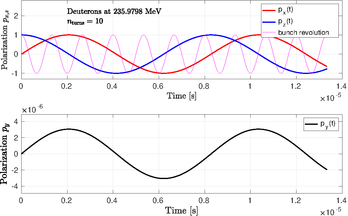
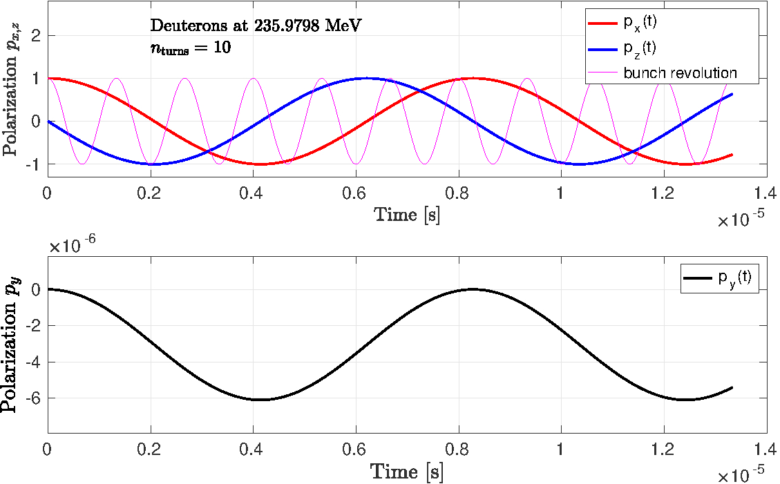
It is clearly visible that the polarization evolution occurs counter-clock wise with respect to the clock-wise rotation of the particles in the ring, since the deuteron factor is negative.
III RF Wien filter in a ring
III.1 Electric and magnetic fields of the RF Wien filter
The RF Wien filter, described Slim et al. (2016), has been designed in order to be able to manipulate the spins of the stored particles, avoiding as much as possible, the effect on the beam orbit. To this end, great care was taken to minimize the unwanted field components of the Wien filter and to characterize them via the Polynomial Chaos Expansion Slim et al. (2017c). In EDM mode, the main component of the magnetic induction is oriented along the -axis, and the main component of the electric field along the -axis.
In order to avoid betatron oscillations in the beam, the magnetic and electric field must be matched to each other to provide a vanishing Lorentz force (see Eq. (3) of Slim et al. (2016)),
| (20) |
According to a full-wave simulation (FWS) 666CST Microwave Studio - Computer Simulation Technology AG, Darmstadt, Germany, http://www.cst.com., including the ferrite cage (see label 6 in Fig. 1 of Slim et al. (2016)), for an input power of , a field integral of along the beam axis of
| (21) |
is obtained. Here, the active length of the RF Wien filter Slim et al. (2016), denoted by
| (22) |
is defined as the region, where the fields are non-zero. Under these conditions, the corresponding integrated electric field components with ferrites are
| (23) |
The design and construction of the RF Wien filter includes a ferrite cage surrounding the electrodes, which improves the field homogeneity and increases the magnitude of the fields Slim et al. (2016). However, in order to simplify the installation, the RF Wien filter was installed at COSY without ferrites, and in addition, it was decided to proceed without ferrites until a first direct deuteron EDM measurement is available.
For this situation without ferrites, and for an input power of [ignoring the unwanted components of the field integrals (, , and , )], one obtains from the full-wave simulation (FWS)
| (24) |
The ratio of electric and magnetic field integrals from the FWS yields
| (25) |
should ideally be equal to unity. The subsequent calculations use the field integrals of an idealized WF with vanishing Lorentz force , given in the last column of Table 2.
A field amplification factor is applied in the simulations to increase the field integrals of the ideal RF Wien filter (last column Table 2) in the simulations, so that
| (26) |
The field amplification allows one to speed up the simulation calculations accordingly, without affecting other aspects of the spin dynamics of the polarization evolution in the ring. In the description of the spin evolution via spin rotations on the closed orbit, momentum and position kicks are not considered.
| Field integrals RF Wien filter | with ferrites | without ferrites | |
|---|---|---|---|
| (real WF) | (real WF) | (idealized Wien filter) | |
| [V] | |||
| [T m] | |||
III.2 Rotations induced by the RF Wien filter
The effect of the RF Wien filter on the polarization evolution in the ring is implemented by an additional rotation matrix. The spin rotation in the Wien filter depends on the applied field integrals (right column of Table 2), multiplied by the factor .
III.2.1 Spin rotation angle in the Wien filter
In the following, the spin rotation angle in the RF Wien filter is calculated numerically using the Thomas-BMT equation of Eqs. (1) and (2) with . We start with an initial spin vector
| (27) |
and we compute the final polarization vector via
| (28) |
Electric and magnetic field vectors for in Eq. (2) are obtained by computing the average fields from the idealized field integrals of the RF Wien filter (last column of Table 2), given by
| (29) |
where the effective length of the Wien filter is taken from Eq. (22). These conditions provide for a vanishing Lorentz force [see also Eq. (20)].
After passing the RF Wien filter once, the final polarization vector is given by
| (30) |
and, after normalizing to unity, the angle between and is determined from the four-quadrant inverse tangent
| (31) |
with
| (32) |
The spin-rotation angle in the RF Wien filter, divided by the idealized transverse magnetic field integral from Table 2, yields
| (33) |
Validating the numerical result for the spin-rotation angle in the RF Wien filter obtained in Eq. (32) against the analytic expression, given in (Saleev et al., 2017, Eq. (13)), yields
| (34) |
where the time interval in the Wien filter has been expressed through the length .
The spin rotation angle in the RF Wien filter, given in Eq. (34), constitutes an upper limit, which corresponds to a situation when a sharp -function-like bunch passes through the device. Realistically, the bunch distribution has to be folded in, and the spin-rotation angle will be reduced correspondingly.
III.2.2 RF Wien filter rotation matrix
The spin-rotation angle of the RF Wien filter changes as function of time according to
| (35) |
where
| (36) |
The Wien filter is operated on some harmonic of the spin-precession frequency [Eq. (17)], given by
| (37) |
The RF Wien filter rotation matrix is given by
| (38) |
where in the generic case, is a unit vector along the magnetic field of the Wien filter. The case
| (39) |
for instance, denotes the Wien filter EDM mode. The RF Wien filter matrix is only evaluated once per turn when the condition
| (40) |
is met stroboscopically, otherwise, the implemented function returns the unit matrix.
When the Wien filter is rotated around the beam axis () by some angle , and
| (41) |
the oscillations also receive a contribution from the rotation of the MDM in the horizontal magnetic field.
III.3 Polarization evolution in the ring with RF Wien filter
The evolution of the polarization vector as function of time in the ring with RF Wien filter can be numerically evaluated via
| (42) |
The corresponding situation is illustrated in Fig. 3. The spin rotations in the ring can be described by . A turn begins with the revolution in the ring, and it ends with one pass through the RF Wien filter. Between two successive points in time at which a particle encounters the RF Wien filter, its spin is just idly precessing in the machine.
According to Eq. (42), the spin motion is stroboscopic in the sense that the spin rotation follows the angle of the RF Wien filter [Eq. (35)] turn-by-turn. The RF Wien filter therefore induces a stroboscopic turn-by-turn conversion of the transverse in-plane polarization into a vertical one (or vice versa). Using the Bogolyubov-Krylov-Mitropolsky (BKM) averaging method Bogoliubov and Mitropolsky (1961), the turn-by-turn evolution of the polarization can be approximated by the continuous dependence on the revolution number, given by [Eq. (16)]. For the generic orientation of the RF Wien filter, the BKM averaged buildup of the vertical polarization proceeds with the resonance tune (or strength) Saleev et al. (2017)
| (43) |
The direct simulations using Eq. (42), discussed below, will furnish important crosschecks with respect to the accuracy of the analytic approximations based on the BKM averaging.
III.4 Radial magnetic RF field in the Wien filter
III.4.1 Driven oscillations and resonance strength
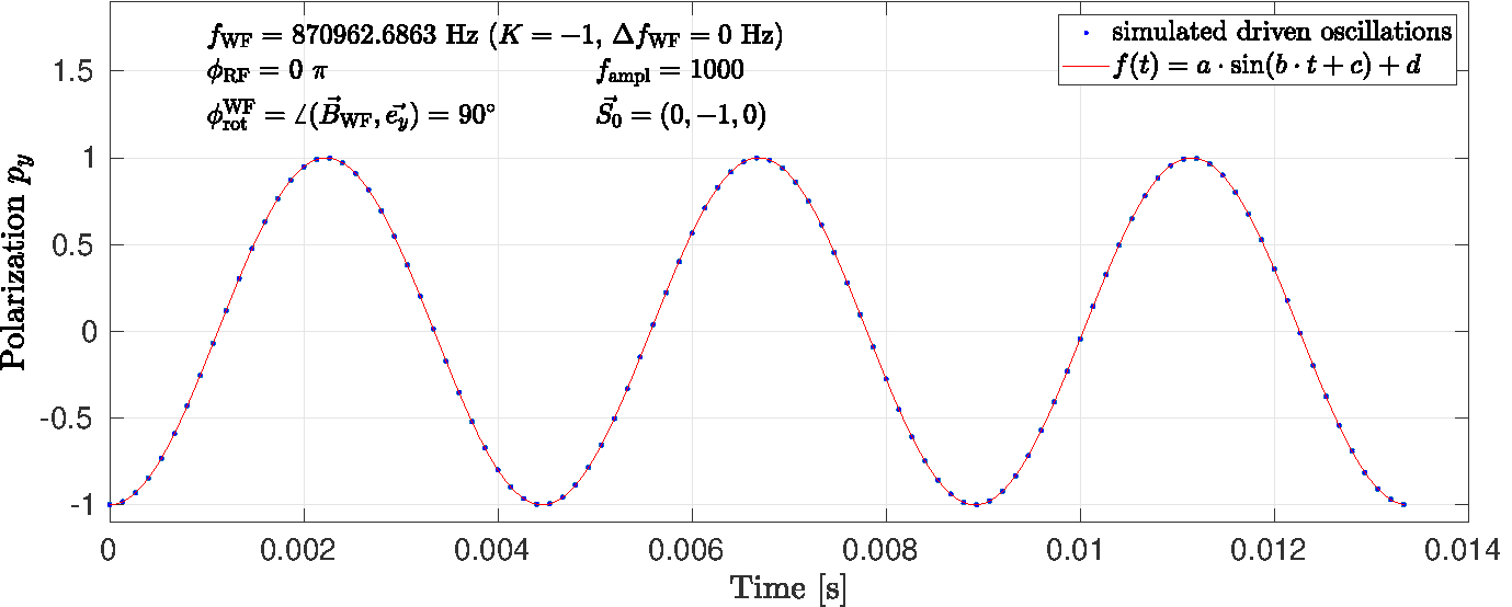
As an illustration of the principal features of the polarization evolution, we take the case where the RF Wien filter is rotated in the so-called MDM mode with magnetic field along , i.e., for , where the initial polarization .
Using the function for , given in Eq. (42), for the conditions of Table 1, driven oscillations for RF Wien filter with magnetic field aligned along , for [see Eq. (41)] were simulated. One example for is shown in Fig. 4. Subsequently, the simulated oscillation data were fitted using the function
| (44) |
The quality of the fit to the numerical data is evaluated in terms of squared deviations via
| (45) |
where the weight factors are , and . In the last row of Table 3, the reduced is given, where , and , since the fitted function in Eq. (44) has four parameters.
| () | |
The resulting angular oscillation frequency , given in Table 3, was obtained using the field integrals, listed in Table 1. The uncertainties were obtained using a computation time of about 777Lenovo T460s, all calculations use 64-bit double-precision floating point numbers, for which the .. The oscillation frequency normalized to the real magnetic field integral yields,
| (46) |
The driven oscillations of the vertical polarization (Fig. 4) are induced by the horizontal magnetic field of the RF Wien filter that couples to the deuteron MDM. Since the device is operated exactly at the spin-precession frequency, the associated resonance strength or resonance tune Saleev et al. (2017) can conveniently be expressed via
| (47) |
III.4.2 Width of the spin resonance
The detuning of the frequency at which the RF Wien filter is operated can be parametrized by substituting in Eq. (36)
| (48) |
As shown in Fig. 5, the resulting oscillation pattern is modified. Specifically, the oscillation amplitude of in Eq. (44) is altered. The argument of the sine function is subjected to the substitution
| (49) |
which can readily be derived from Eqs. (A7) and (A8) of Saleev et al. (2017).
From a number of such simulations,
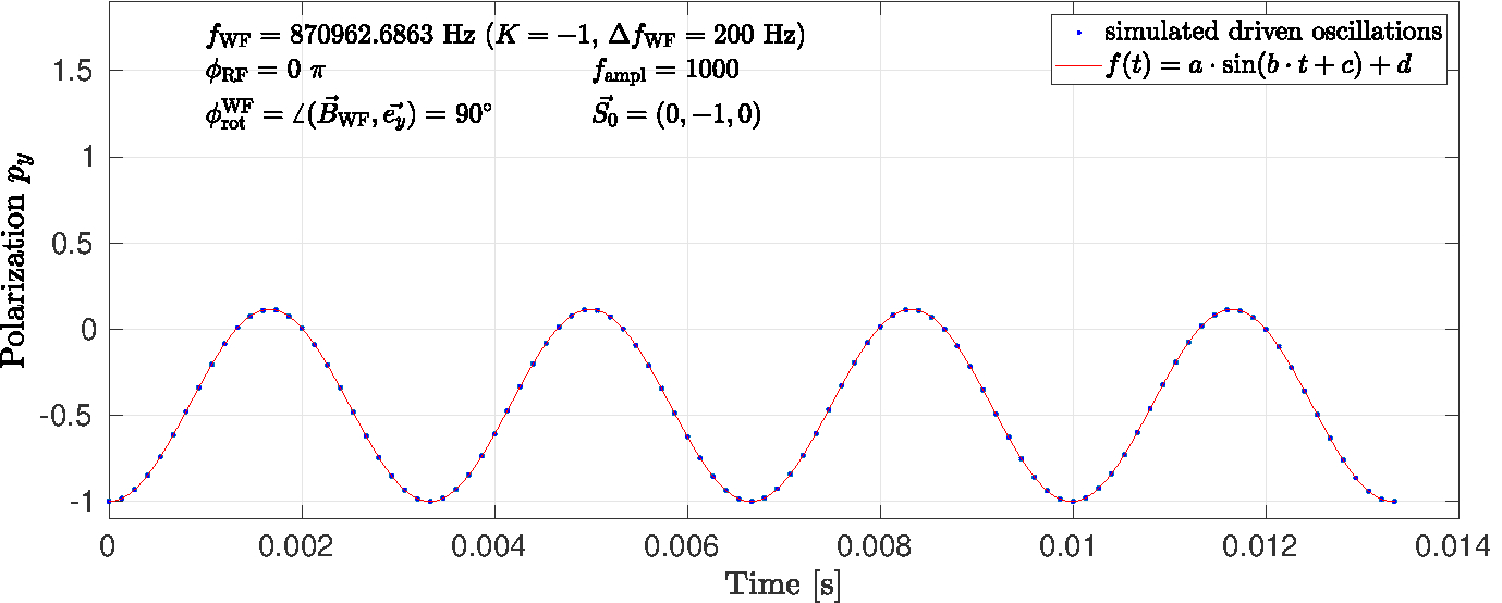
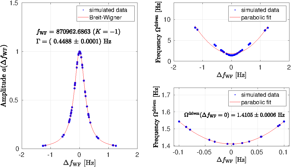
the oscillation amplitudes and the oscillation frequencies as function of are obtained by fitting. In order to reduce the time required for the simulations, again a field amplification factor of was used. This leads to oscillations that are faster by the same factor. The simulated data can be described by a Lorentz curve of the form,
| (50) |
The left panel of Fig. 6 shows the simulated spin resonance, already corrected for the field amplification factor. For all harmonic excitations used in the RF Wien filter, the simulations yield, within errors given, the same width of
| (51) |
Using the nominal fields of the RF Wien filter (right column of Table 2 and ), the driven oscillations have a frequency of
| (52) |
The two panels on the right side show that a quadratic fit to the driven oscillation frequency should be only used in a narrow region around the minimum.
The quality factor of an underdamped oscillator is defined as
| (53) |
where is the full width at half maximum, and is the resonance frequency. Thus, at a deuteron momentum of , a theoretical estimate of the value of the oscillating deuteron spins in the machine amounts to
| (54) |
III.5 Vertical magnetic field in the RF Wien filter
With a vertical magnetic field in the RF Wien filter (), in the expression of the spin-resonance strength [Eq. (43)], we then have
| (55) |
In this case, the experimental determination of the resonance strength amounts to the determination of the tilt angle and of the associated EDM, via Eqs. (11) and (3).
III.5.1 Polarization evolution with development of
In the following, the polarization buildup in the machine is addressed. The interplay of the different frequencies involved is illustrated in Fig. 7.
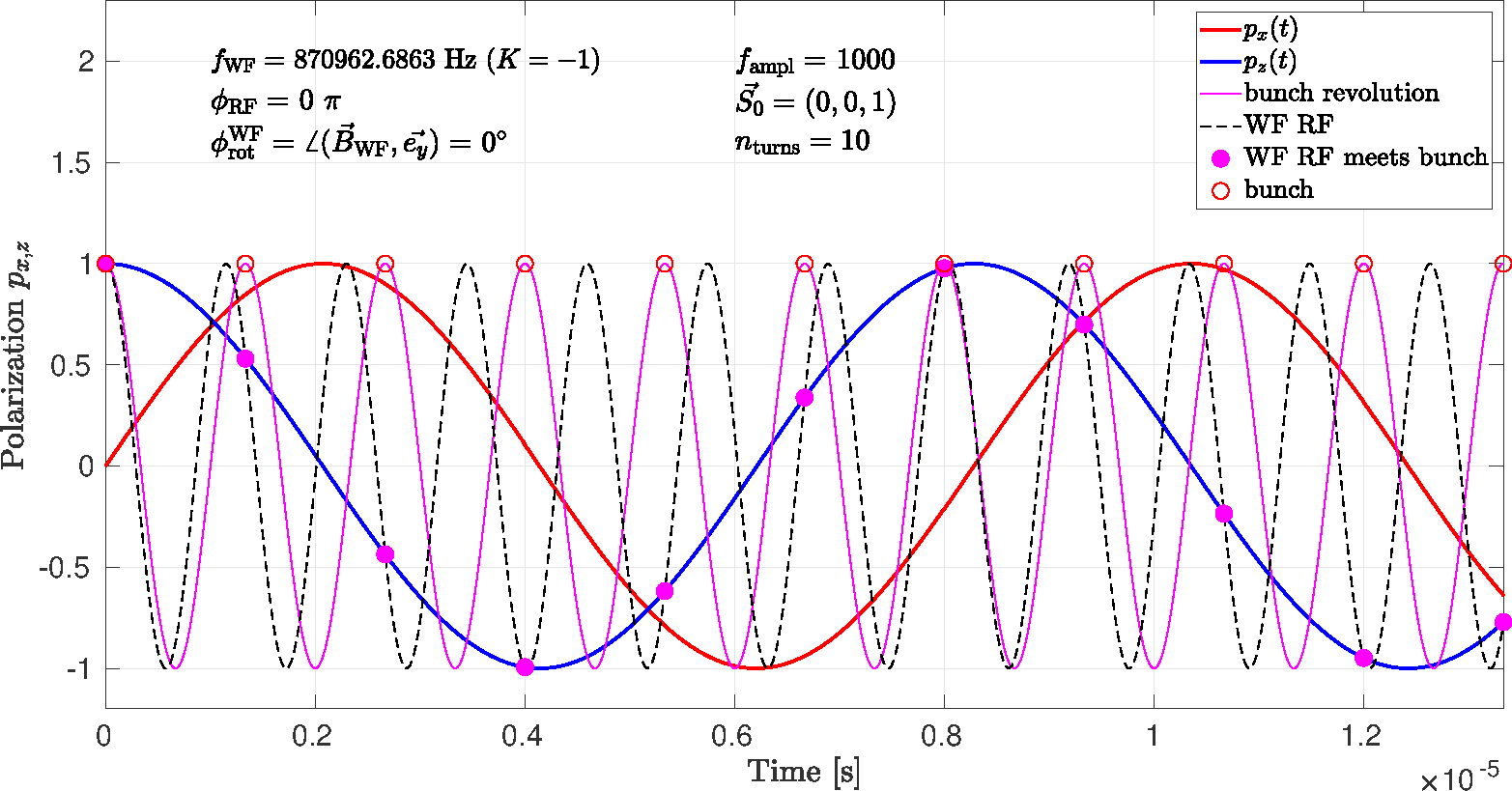
The same situation as in Fig. 7 is depicted in Fig. 8, the only difference is the larger turn number. The graph illustrates the experimental evidence for an EDM, namely a non-vanishing slope of the vertical polarization . This slope describes the steady out-of-plane rotation of the polarization vector on the background of oscillations shown in the bottom panels of Fig. 2, where the oscillation amplitude perfectly matches with the angle , used in the simulation (see Table 1).
The slope can be determined by fitting using
| (56) |
where is not a fit parameter, but taken from Eq. (17).
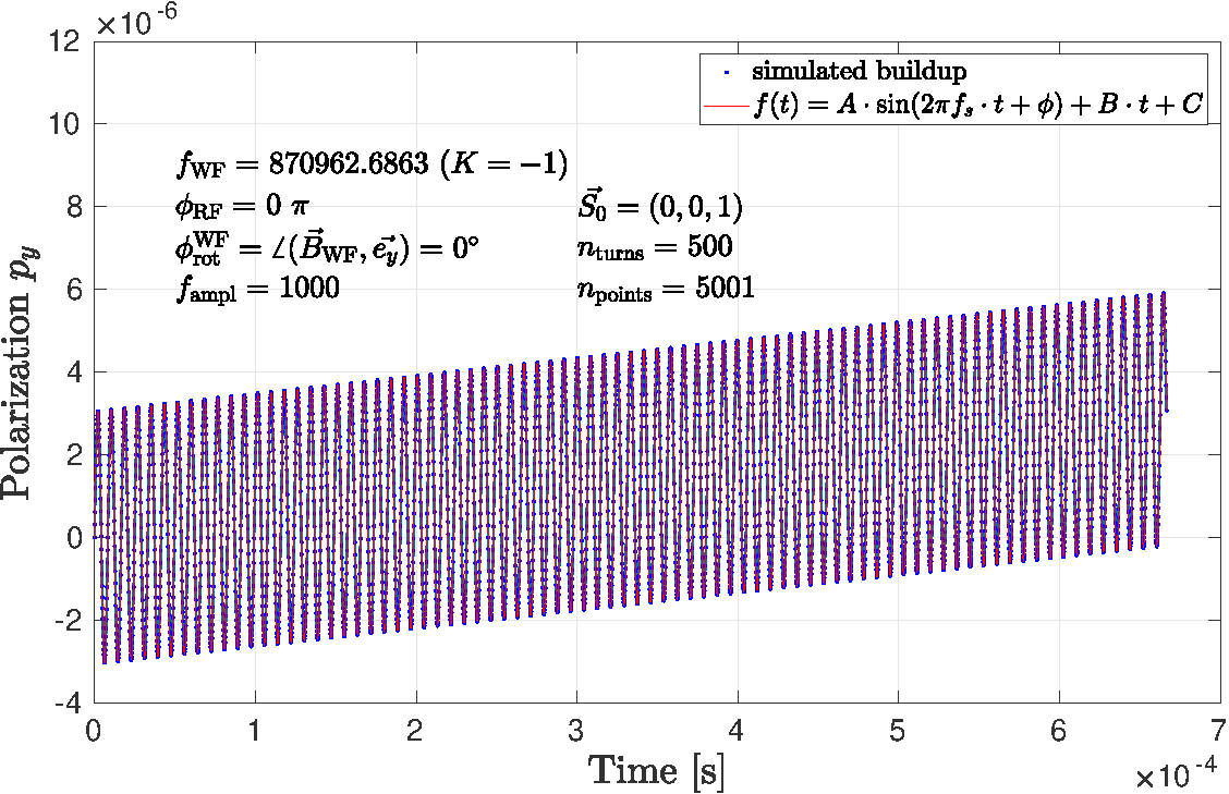
Thus, using the above parametrization, the initial slope is given by
| (57) |
III.5.2 dependence on the phases and
The RF phase is introduced in Eq. (35). During a real experiment, this phase needs to be maintained by a phase-locking system (for details see Hempelmann et al. (2017)). Another way to parametrize the same effect is via the angle , which is illustrated in Fig. 9(a).
Within the formalism described in Saleev et al. (2017), it is the interplay between the stable spin axis at the RF Wien filter and its magnetic axis ( that controls via the orientation of . On the other hand, one could start by fixing the orientation of by picking some angle . The resulting evolution of , however, must be the same, except for a possible constant shift between the two phases and .
The buildup of a vertical polarization component, which is equivalent to a rotation of the polarization vector out of the ring plane due to the EDM for a set of random azimuthal angles and has been computed. The results are shown in Fig. 10.
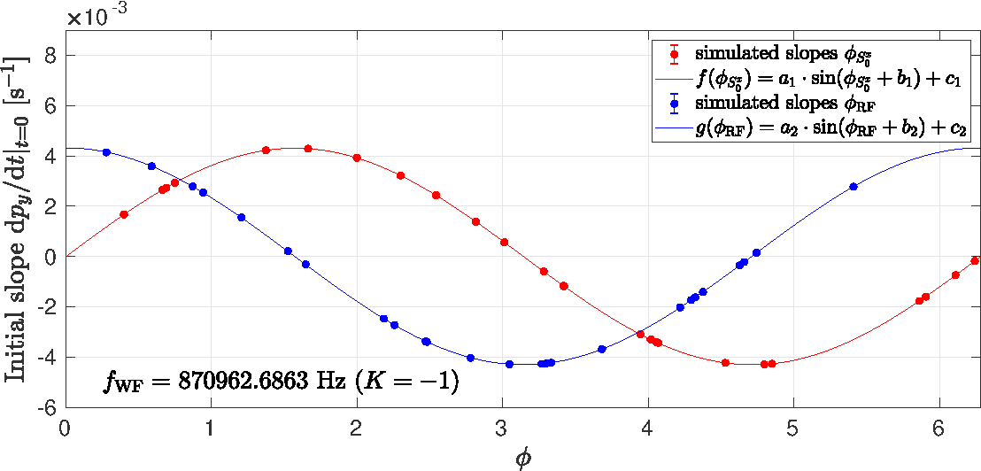
Within the given uncertainties, the two simulated data sets for and , as expected, yield the same results. The only difference is a phase shift of between and . The weights that are used to find the optimum parameters are all equal in the two data sets.
Correcting the initial slope parameter in Table 4 for the employed field amplification factor used in the simulation, yields a prediction for the initial slope that one would expect in an ideal ring in the presence of an EDM of . For an initial polarization , with the parameters for the idealized RF WF, given in the last column of Table 2, one obtains
| (58) |
Since the comparison of with experiment requires knowledge of the magnitude of , the approach taken in Hempelmann et al. (2018) is convenient, because the angle of the out-of-plane rotation is independent of the magnitude of the beam polarization. The quantity of interest, indicated in Fig. 9(b), in that case is . The polarimeter measures , irrespective of the in-plane polarization , given by
| (59) |
From this it follows that
| (60) |
III.5.3 Initial slope versus slow oscillation amplitude
Figure 11(a) shows the initial slopes for four different assumed EDMs, for an ideal ring and an idealized Wien filter, based on the conditions listed in Table 1. The EDMs manifest themselves twofold, namely in different slopes and in larger amplitudes of the fast oscillation.
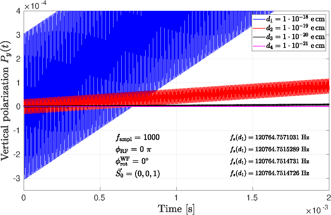
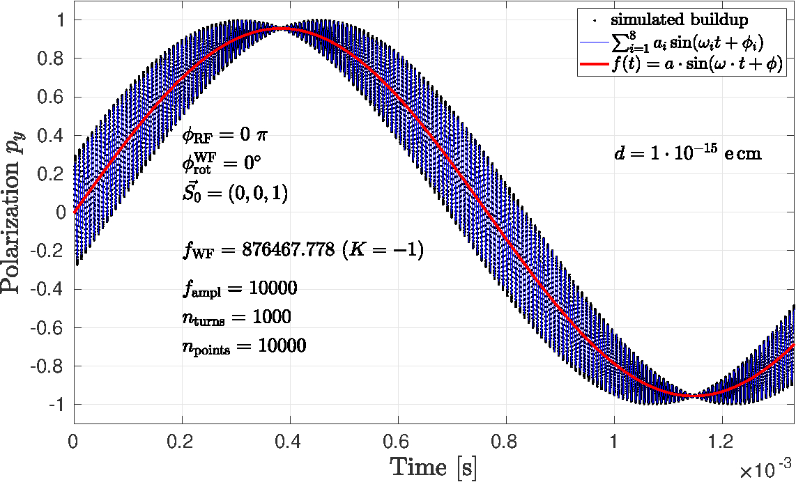
The linear slopes in Fig. 11(a) are of course just the very beginning of a sinusoidal oscillation that becomes visible only when the EDM becomes large, as depicted in Fig. 11(b), where
| (61) |
has been used in the simulation.
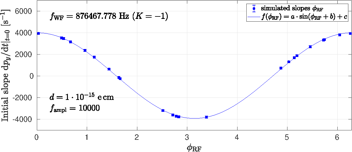
The initial slope of the vertical polarization component is related to the strength of the EDM spin resonance. Another way to obtain this information is to vary the RF phase , as indicated in Fig. 10. The initial slope can of course also be obtained from the slow oscillation. The vertical polarization can be described by
| (62) |
which respects the property that for any , . The derivative of with respect to time is
| (63) |
where the value given corresponds to the situation shown in Fig. 11(b).
Numerically, the red curve in Fig. 11(b) has been parametrized by the function
| (64) |
It turns out that the amplitude of the averaged oscillation [red curve in Fig. 11(b)] can be determined directly from the tilt angle of the stable spin axis due to the EDM, via
| (65) |
With , within the errors, one obtains a perfect match to the value of given by
| (66) |
The envelope of the fast oscillations is perfectly consistent with the law
| (67) |
According to Saleev et al. (2017), the EDM induced angular oscillation frequency in Eq. (62) can be expressed through the EDM resonance strength and the angular revolution frequency , via
| (68) |
In terms of the initial slope, the resonance strength is given by
| (69) |
While the slopes can be easily determined as function of , the latter method using Eq. (69) clearly also requires knowledge about the oscillation amplitude . Knowing the initial slopes alone, does not allow one to determine the resonance strength .
Using the technique of variation of , as shown in Fig. 10, Fig. 12 yields an initial slope of
| (70) |
which agrees numerically well within errors with the value given in the last line of Eq. (63).
III.5.4 Determination of the running spin tune, based on the polarization evolution
The standard definition of the spin tune as a rotation around the local stable spin axis at every point in the machine does not involve a time dependence of the polarization evolution, like the one generated by the RF Wien filter. When a time-dependent polarization is involved, in the following, the term running or instantaneous spin tune is used. In case there is a time-dependent or instantaneous spin tune, the direction of also changes as function of time, i.e., (see further Sec. III.5.5).
Using the numerical simulations for , or any other spin-evolution function, one can numerically determine the running spin tune in the following way. For this one needs three spin vectors from the spin-evolution function, say
| (71) |
Using these three vectors, two more vectors are constructed,
| (72) |
The in-plane angle between and can be used to determine the running, time-dependent spin tune . To this end, we define the normal vector of the plane that contains and ,
| (73) |
that corresponds to the instantaneous (running) spin axis. Using , we find the in-plane components of and , via
| (74) |
The normalized versions of these vectors are called
| (75) |
and the running spin tune is determined from
| (76) |
The factors in front of take care that generates the correct sign based on the -factor and the number of spin-precessions per turn.
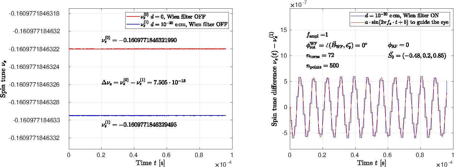
As a cross check of the algorithm, with RF WF switched off, for the beam conditions given in Table 1, Eq. (76) yields
| (77) |
where all three numbers have been calculated using Eq. (76). As an additional cross check, the difference of the spin tunes
| (78) |
which is very close to the achievable machine precision44footnotemark: 4.
During a revolution in the machine, as prescribed by using Eq. (42), the spin tune remains constant during each turn (see Fig. 13). When the RF Wien filter is switched on, due to the additional spin rotation in the time-varying RF field, the spin tune jumps from turn to turn. The oscillation amplitude of the spin tune variation due to the RF Wien filter using a power of (see Table 1) is well consistent with the expectation from the spin rotation formalism
| (79) |
The average spin tune, however, remains constant.
III.5.5 Instantaneous spin orbit determination based on
The running spin orbit vector can be easily determined from the procedure of the previous section, using the normal vector , defined in Eq. (73),
| (80) |
Similarly to the running (instantaneous) spin tune, the instantaneous spin orbit (running spin axis) exhibits oscillatory in-plane components.
IV Polarization evolution with RF Wien filter and solenoids
IV.1 Evolution equation with additional static solenoids
In the course of this paper, with the RF Wien filter in EDM mode (), the EDM interaction with the motional electric field in the ring, was the only source of up-down spin-oscillations.
In the following, two static solenoids in the straight sections will be added to the ring. Besides that, we shall make an allowance for rotations of the RF Wien filter around the longitudinal (momentum) direction. Such rotations induce a radial magnetic RF field, and, in conjunction with the solenoidal magnetic fields, we start mixing the EDM and MDM induced rotations. The idea, common to all EDM experiments, is to disentangle the EDM signal from an extrapolation to a vanishing MDM contribution Pendlebury et al. (2015); Afach et al. (2015).
With two static solenoids added to the ring, the resulting sequence of elements is depicted in Fig. 14.
The one-turn ring matrix can be split into two arcs, one arc made of the dipole magnets D1 to D12, and the second arc made of dipoles D13 to D24. Since
| (81) |
the two additional solenoids can be inserted before and behind arc 2, leading to
| (82) |
invoking again the generic rotation matrix from Eq. (12).
In a similar fashion as in Eq. (42), one can write for the polarization evolution,
| (83) |
IV.2 Spin-rotation angle in a static solenoid
In a solenoidal magnet with a field integral , the spins are rotated around the longitudinal direction , and the rotation angle is given by
| (84) |
The spin rotation angle in the solenoid for deuterons at a momentum of , normalized to the magnetic field integral, amounts to
| (85) |
IV.3 Spin tune and spin closed orbit with solenoids using
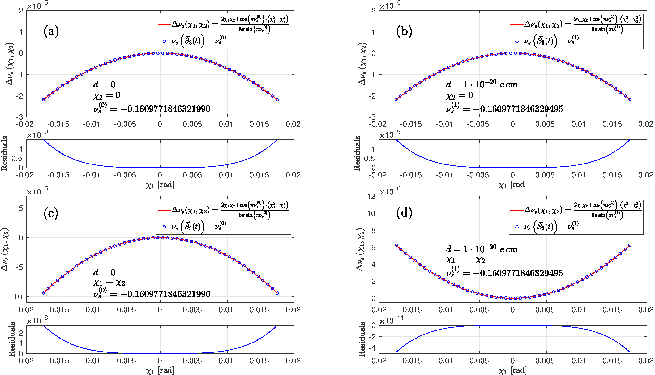
In the following, the abbreviation, e.g., is used. For an ideal ring, free of magnetic imperfections, the spin tune change , due to solenoids S1 and S2 in the ring (see Fig. 14), the left side of Eq. (30) of Ref. Saleev et al. (2017) can be approximated by , where denotes the unperturbed spin tune in the machine. For small spin rotation angles in the solenoids, Eq. (30) can thus be approximated by
| (86) |
IV.4 Spin-closed orbit in a non-ideal lattice
The static solenoids or magnetic imperfections in the ring affect the spin-closed orbit vector in the machine. The situation is similar to the one depicted in Fig. 1, but there, only the tilt due to the EDM was taken into account. The presence of static solenoids in the ring can be numerically evaluated using Eq. (80) with [Eq. (83)].
Since the time begins to count right behind the RF Wien filter (see Fig. 14), evaluation of Eq. (80) at (or integer multiples of [see Eq. (40)]), yields the orientation of the spin-closed orbit vector at the RF Wien filter
| (87) |
Figure 16 shows how the axis is affected by the solenoids S1 and S2, and the presence of an EDM .
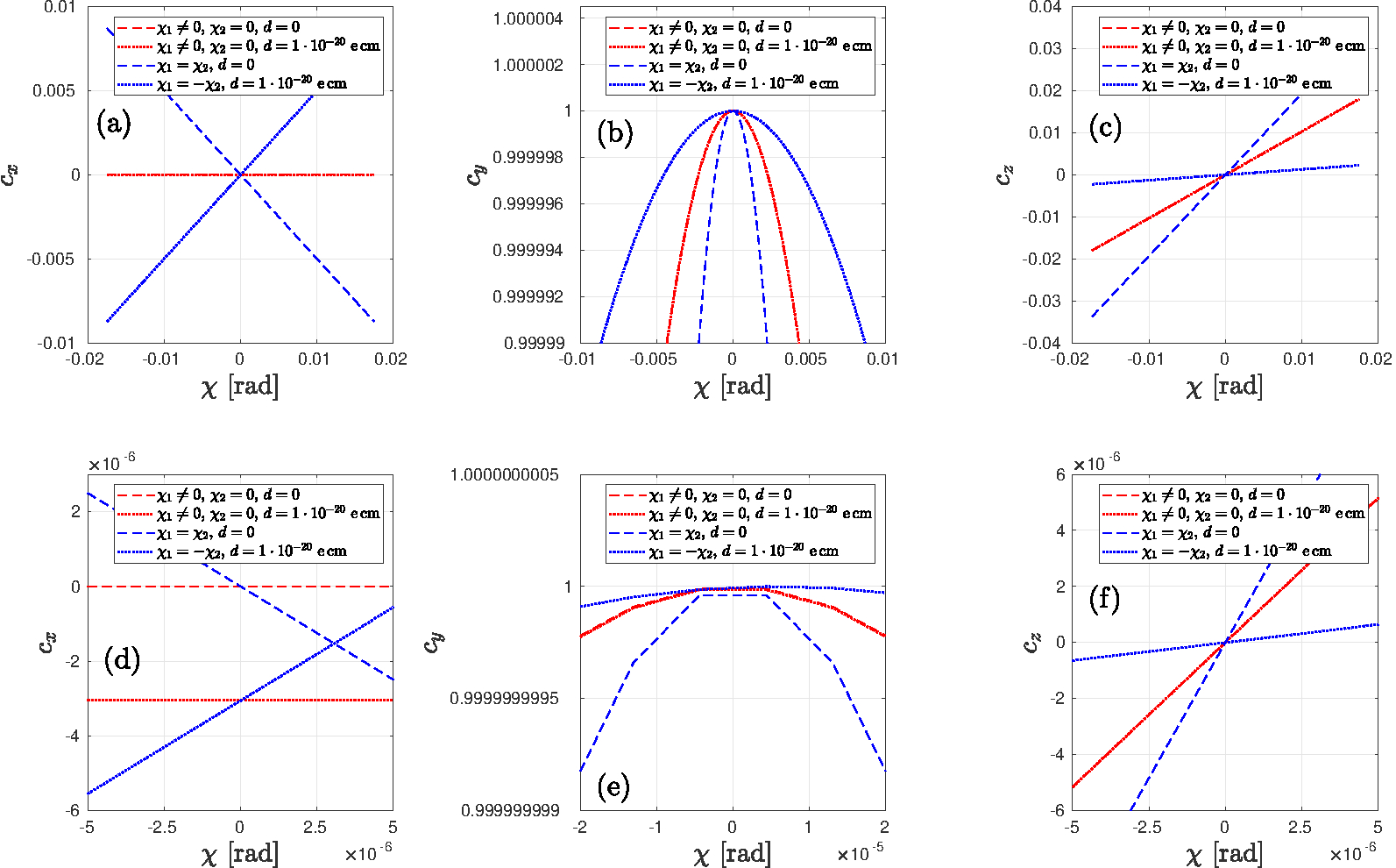
For numerical comparisons, a number of special cases are numerically evaluated in Table 5.
| [] | [] | [e cm] | |||
|---|---|---|---|---|---|
| 0 | |||||
IV.5 Strength of the EDM resonance
As depicted in Fig. 13, and already discussed in Sec. III.5.4, the operation of the RF Wien filter modulates the spin tune. While the average spin tune is equal to the one obtained when the RF Wien filter is switched off, solenoids and magnet misalignments in the ring, however, affect the spin tune. Therefore, the spin-precession frequency and thus the frequency at which the RF Wien filter should be operated, differs from the unperturbed spin tune. The spin tune must be determined anew for every solenoid setting to ensure that the resonance frequency for the RF Wien filter is given by
| (88) |
and this frequency needs to be used in [Eq. (35)], as it controls the RF Wien filter spin-rotation matrix [Eq. (38)].
The EDM resonance strength , actually a resonance tune, is defined as the ratio of the angular frequency of the vertical polarization oscillation induced by the EDM relative to the orbital angular frequency ,
| (89) |
Since corresponds to [first line in Eq. (63)], the resonance strength can in principle be determined from a single observation of . Alternatively, the resonance strength can be determined from the last line in Eq. (63) via
| (90) |
but this requires that the initial slopes need to be determined as function of, e.g., . The statistical aspects of this will be further elucidated in Sec. IV.5.2.
IV.5.1 Evolution of as function of and
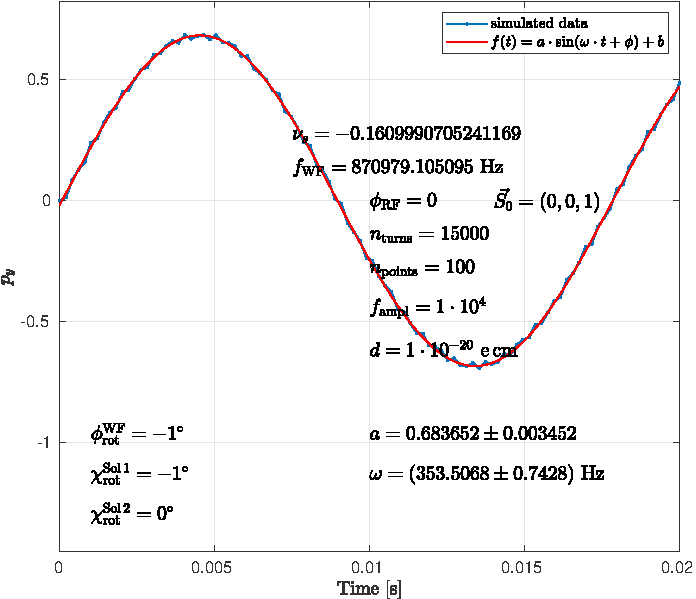
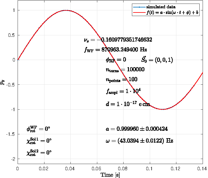
The EDM resonance strength [Eq. (89)] manifests itself in the oscillation frequency, as illustrated in Fig. 17 for two pairs of Wien filter rotation angle and spin-rotation angle in solenoid S1, , where .
The resulting oscillation pattern of is fitted using
| (91) |
amplitude and frequency are given in each panel, together with various other parameters. The calculation for the ideal ring situation in panel (b) uses a times larger assumed EDM value of and a larger number of turns , in order to make the oscillations of visible as well.
IV.5.2 Comparison of from and by variation of
One would expect that the variation of the RF phase will affect the resulting oscillation amplitudes and offsets of Fig. 17, while the oscillation frequencies , and thus the resonance strengths remain unchanged.
In the panels of Fig. 18, for the same combinations of , shown in Fig. 17, and the oscillation frequency are computed for 36 randomly picked values of . The graph illustrates that in the presence of solenoid fields and RF Wien filter misalignments, the determination of by variation of , making use of Eq. (90) yields results comparable to the direct determination of the resonance strength from the oscillation frequency via Eq. (89). The oscillation amplitudes and exhibit an identical dependence on , while the obtained resonant tune remains constant over the whole range of .
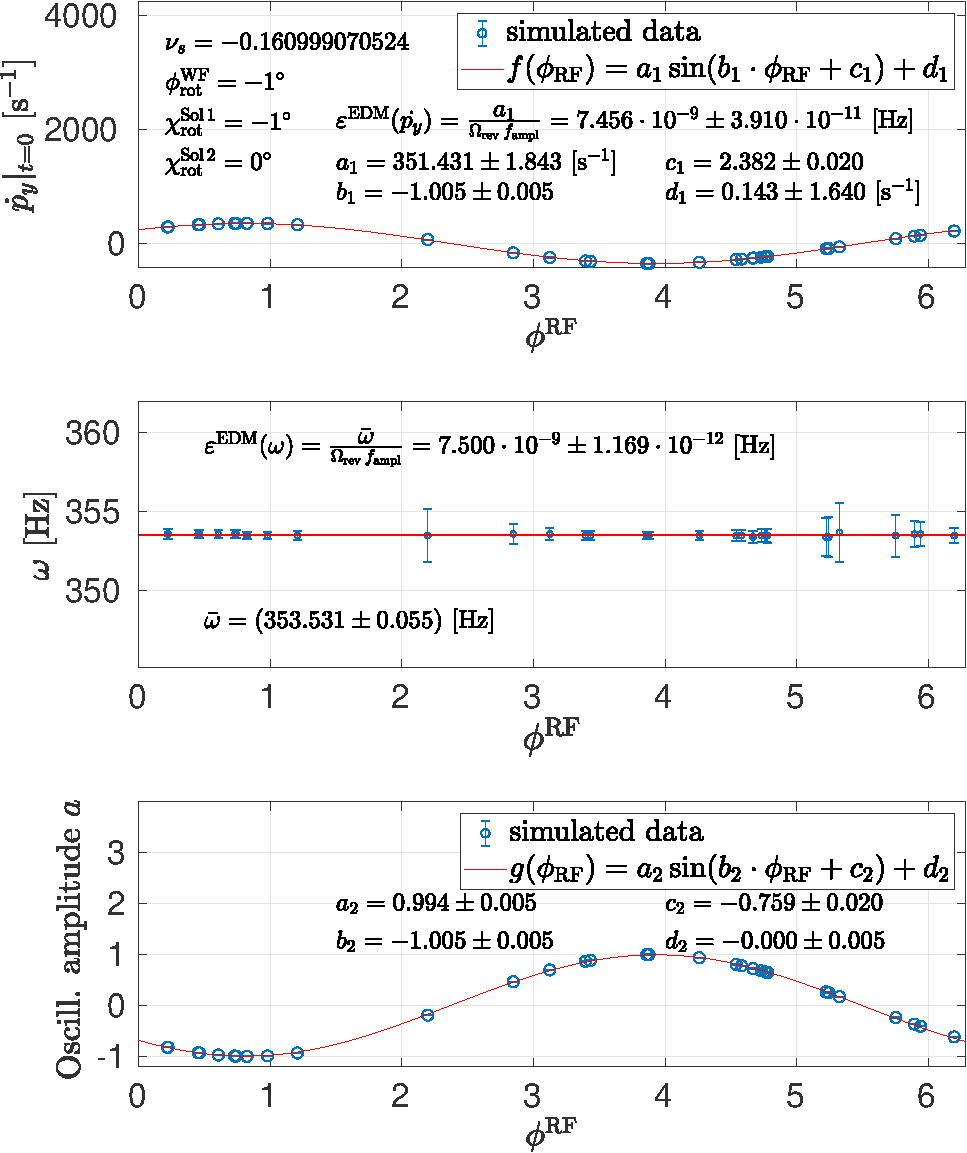
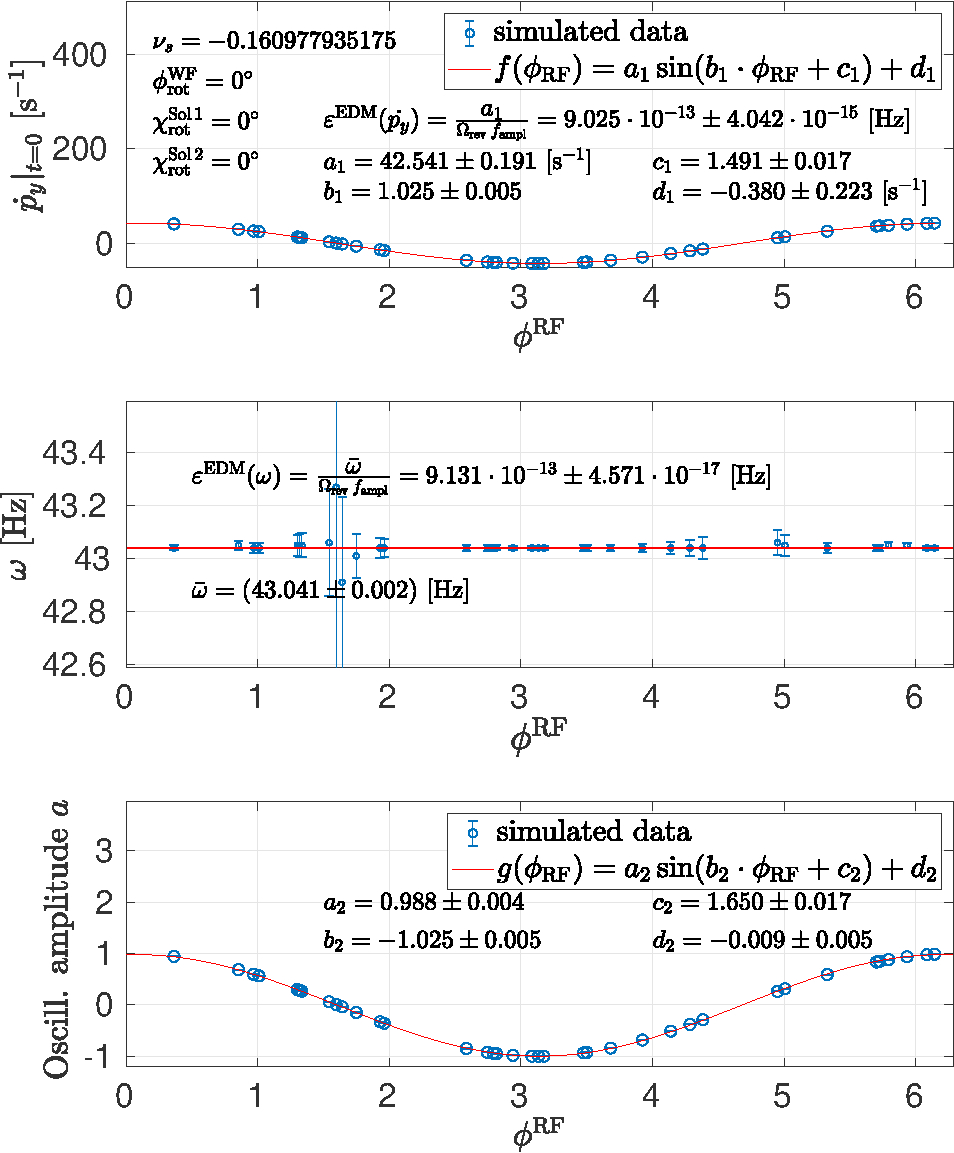
The resonance strengths extracted from and make use of the very same simulated data. The results are summarized in Table 6, where for the numbers that should match, the same color is used. Although the different extraction methods show good overall agreement, the uncertainties of , however, are substantially smaller than those from by a factor of at least . The reason for this is that in general frequencies can be measured more accurately than other quantities, and the determination of involves fewer uncertainties in the error propagation. The most accurate determinations are obtained from when .
| [ Hz] | ||||
|---|---|---|---|---|
| from | ||||
| from | ||||
| from | ||||
| from | ||||
| from | ||||
| from | ||||
In the following, we briefly comment on some features of the results obtained so far (Fig. 17, Table 6). We observe that numerically . Then, according to Appendix A, we expect
| (92) |
in good agreement with the results shown in Fig. 18. The resonance tunes determined from and from are identical. For the above reason of and small EDM contribution, the equalities
| (93) |
hold.
IV.6 Resonance strength for random points
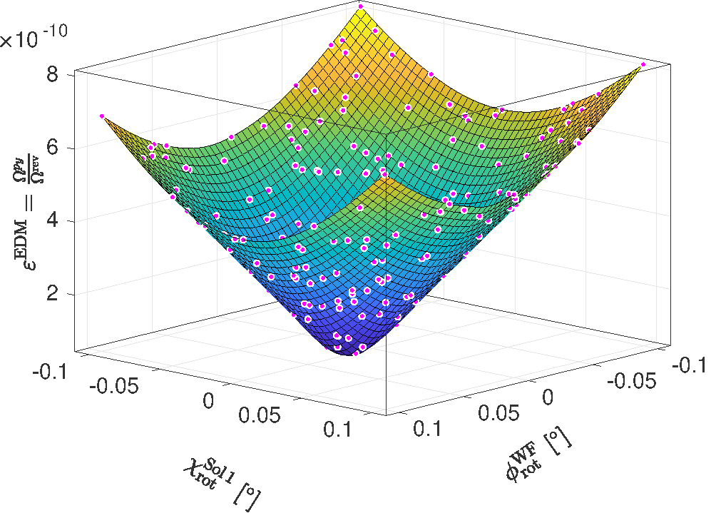
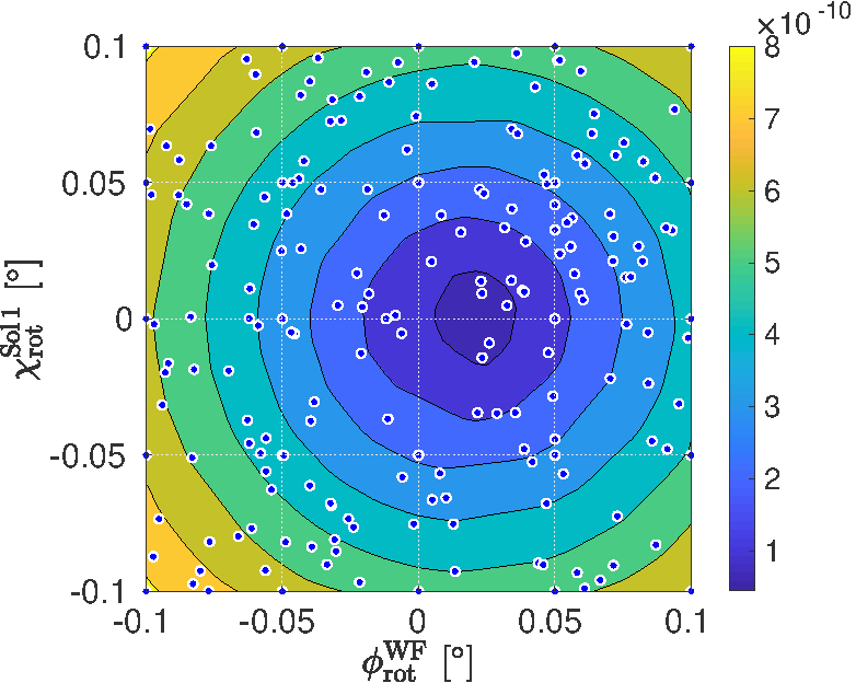
The resonance strengths shown in Fig. 19 are obtained using the fit function of Eq. (91) () and then Eq. (89) for a set of randomly chosen pairs of and . For all points, and
Using the evolution function [Eq. 83] which includes the ideal ring with solenoid S1 and the RF Wien filter and an assumed EDM of , for which the EDM tilt angle is , in the angular range, , , and , the pattern shift is clearly visible, as seen in Fig. 19(b).
The relative uncertainties of the points shown in Fig. 19 were obtained from the fits. In panels 19(a) and 19(b), ranges from to .
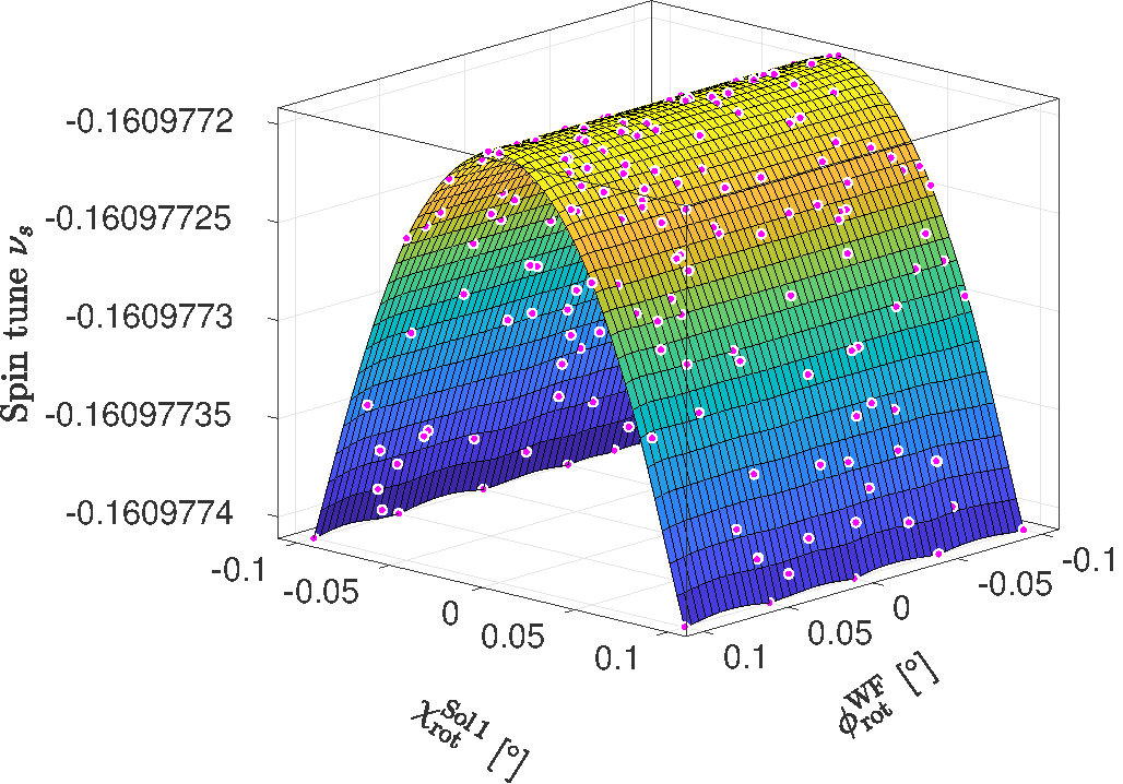
For the set of points shown in Fig. 19, the initial spin tunes , i.e., before the RF WF is turned on, are shown in Fig. 20. The result indicates the familiar quadratic dependence , described by Eq. (86).
IV.7 Characterization of
IV.7.1 Operation of RF Wien filter exactly on resonance
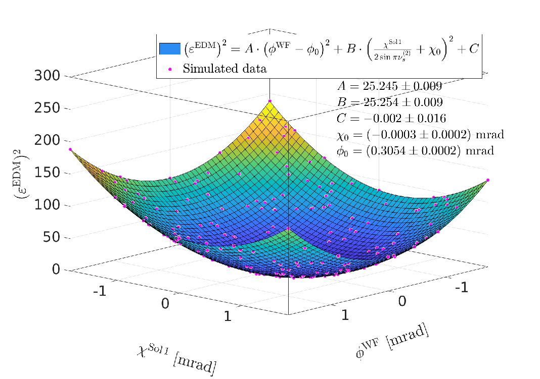
In this section, the contour of the surface , shown in Fig. 19(a), is compared to the theoretical expectation, given in Eq. (106). The functional dependence describes a quadratic surface, also know as Elliptic Paraboloid, and is used here in the form
| (94) |
where the unperturbed spin tune for the EDM of , assumed in the simulation, is given by
| (95) |
It should be emphasized that the simulations shown in Fig. 19 reflect the situation when the RF Wien filter is operated exactly on resonance. During the corresponding EDM experiments in the ring, however, a certain spin-tune feedback is imperative to maintain for long periods of time the resonance condition, i.e., the spin-precession frequency in Eq. (35), using the measured spin tune Eversmann et al. (2015). To maintain phase and frequency when the RF Wien filter is actively operating, turns out to be much more tricky, and more sophisticated approaches, beyond those outlined in Hempelmann et al. (2017), are presently being pursued by the JEDI collaboration. Only such a phase and frequency lock during a measurement cycle enables one to take full advantage of the large spin-coherence time (SCT) of , achieved by JEDI at COSY Guidoboni et al. (2016, 2018).
The result of a fit without weighting is shown in Fig. 21(a). It should be noted that within the uncertainties obtained from the fit, , while and are compatible with zero. Here, represents a primordial tilt of the stable spin axis at the RF Wien filter along the horizontal axis, . For the model ring, one would expect
| (96) |
a property which is nicely returned by the fit shown in Fig. 21(a).
In addition, the fit to the simulated data is expected to return , given by Eq. (11), and the fitted result
| (97) |
returns this value accurately.
IV.7.2 Validation of the scale of
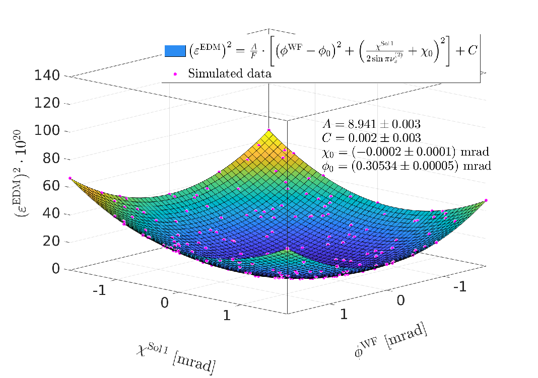
The fit with the elliptic paraboloid, shown in Fig. 21(a), indicates that the surface is described with . In the following, the first fit function from Eq. (94) is slightly altered, yielding
| (98) |
where a factor has been used to scale the resonance strength. The second fit now uses weights derived from the uncertainty of the fitted using Eq. (89). The resulting fit is shown in Fig. 21(b). The agreement between theoretical model and simulated data is good, the .
According to Eq. (106), the factor in front of the brackets in Eq. (98) reads
| (99) |
where the Wien filter rotation angle from Eq. (34) is used. Inserting the numerical value of from the fit (inset Fig. 21(b)), and taking into account that the results are in , the ratio
| (100) |
yields the expected value near unity, which validates the scaling factor in Eq. (106).
The second fit yields a similar value for
| (101) |
compared to the first fit, shown in Fig. 21(a), and and are both compatible with zero.
V Conclusions and outlook
The matrix formalism used here to describe the spin rotations on the closed orbit, i.e., the spin dynamics of the interplay of an RF Wien filter with a machine lattice that includes solenoids, proved very valuable. The general features of the deuteron EDM experiment at COSY can be obtained rather immediately. Of course, the approach taken is no replacement for more advanced spin-tracking codes, but the results obtained here can be applied to benchmark those codes.
In addition, it should be noted that the JEDI collaboration is presently applying beam-based alignment techniques to improve the knowledge about the absolute beam positions in COSY Wagner (2019). Once this is accomplished, the approach described here to parametrize the spin rotations solely on the basis of the closed orbit, will become more realistic.
The polarization evolution in the ring in the presence of an RF Wien filter that is operated on resonance, in terms of the resonance tune or resonance strength is theoretically well understood. This will allow us to investigate in the future effects of increasingly smaller magnetic imperfections, either through additional solenoidal fields in the ring, or by transverse magnetic fields via the rotation of the RF Wien filter around its axis.
In the near future, it is planned to incorporate into the developed matrix formalism also dipole magnet displacement and rotation parameters, available from a recent survey at COSY. This will allow us to determine the orientation of the stable spin axis of the machine at the location of the RF Wien filter, and to extract the EDM from a measurement of the resonance strengths as function of . It is possible to incorporate the spin rotations from misplaced and rotated quadrupole magnets on the closed orbit into the formalism as well.
An approach based on the polynomial chaos expansion has been successfully applied to determine a hierarchy of uncertainties during the construction of the RF Wien filter Slim et al. (2017b). Such a methodology, in conjunction with the spin-tracking approach based on the matrix formalism outlined here, can be employed to efficiently generate a hierarchy of uncertainties for the EDM prototype ring Abusaif et al. (2018) from the different design parameters of the ring.
The spin-tracking approach used here, shall be also applied to study various aspects of the presently applied spin-tune feedback system, used to phase-lock the spin precession to the RF of the Wien filter Hempelmann et al. (2017).
Acknowledgment
This work has been performed in the framework of the JEDI collaboration and is supported by an ERC Advanced-Grant of the European Union (proposal number 694340). The work of N.N.N. was a part of the Russian MOS program 0033-2019-0005. Numerous discussions with colleagues went into this document, foremost we would like to acknowledge those with Volker Hejny, Alexander Nass, Jörg Pretz, and Artem Saleev.
Appendix A Dependence of the EDM resonance strength on and
The functional dependence of a physical rotation of the Wien filter around the beam axis by and of a spin rotation in static solenoids (see Fig. 3) by on the resonance strength [Eq. (89)] is discussed.
At the location of the polarimeter, only the vertical and radial components of the beam polarization [ and ] can be determined. At the RF Wien filter, the orientation of the stable spin axis is denoted by , and in EDM mode the direction of the magnetic field by [see Eq. (39)]. The in-plane thus obviously depends on .
In an ideal all-magnetic ring under consideration, the stable spin axis is close to the vertical direction ,
| (102) |
In EDM mode, the magnetic axis of the RF Wien filter can be approximated by
| (103) |
The stable spin axis can be manipulated by static solenoids in the ring, and the drift solenoids of the electron coolers (or the Siberian snake instead of S1) generate the spin kicks . When both solenoids are turned on, one can write for the stable spin axis
| (104) |
In case solenoid S2 is off (), one obtains
| (105) |
Thus the resonance strength squared can be written as a sum of two independent quadratic functions,
| (106) |
where is defined in Eq. (34).
References
- Weidemann et al. (2015) C. Weidemann, F. Rathmann, H. J. Stein, B. Lorentz, Z. Bagdasarian, L. Barion, S. Barsov, U. Bechstedt, S. Bertelli, D. Chiladze, G. Ciullo, M. Contalbrigo, S. Dymov, R. Engels, M. Gaisser, R. Gebel, P. Goslawski, K. Grigoriev, G. Guidoboni, A. Kacharava, V. Kamerdzhiev, A. Khoukaz, A. Kulikov, A. Lehrach, P. Lenisa, N. Lomidze, G. Macharashvili, R. Maier, S. Martin, D. Mchedlishvili, H. O. Meyer, S. Merzliakov, M. Mielke, M. Mikirtychiants, S. Mikirtychiants, A. Nass, N. N. Nikolaev, D. Oellers, M. Papenbrock, A. Pesce, D. Prasuhn, M. Retzlaff, R. Schleichert, D. Schröer, H. Seyfarth, H. Soltner, M. Statera, E. Steffens, H. Stockhorst, H. Ströher, M. Tabidze, G. Tagliente, P. T. Engblom, S. Trusov, Y. Valdau, A. Vasiliev, and P. Wüstner, Phys. Rev. ST Accel. Beams 18, 020101 (2015).
- (2) JEDI Collaboration, proposals available from http://collaborations.fz-juelich.de/ikp/jedi/.
- Rathmann and Nikolaev (2019) F. Rathmann and N. N. Nikolaev, in 23rd International Symposium on Spin Physics (SPIN 2018) Ferrara, Italy, September 10-14, 2018 (2019) arXiv:1904.13166 [nucl-ex] .
- Slim et al. (2016) J. Slim et al., Nucl. Instrum. Meth. A828, 116 (2016), arXiv:1603.01567 [physics.ins-det] .
- Slim et al. (2017a) J. Slim, F. Rathmann, A. Nass, H. Soltner, R. Gebel, J. Pretz, and D. Heberling, Nucl. Instrum. Meth. A859, 52 (2017a), arXiv:1612.09235 [physics.ins-det] .
- Slim et al. (2017b) J. Slim, F. Rathmann, and D. Heberling, Phys. Rev. E96, 063301 (2017b), arXiv:1707.09274 [physics.comp-ph] .
- Morse et al. (2013) W. M. Morse, Y. F. Orlov, and Y. K. Semertzidis, Phys. Rev. ST Accel. Beams 16, 114001 (2013).
- (8) srEDM Collaboration, proposal available from http://www.bnl.gov/edm/files/pdf/proton_EDM_proposal_20111027_final.pdf.
- Abusaif et al. (2018) F. Abusaif, A. Aggarwal, A. Aksentev, B. Alberdi-Esuain, L. Barion, S. Basile, M. Berz, M. Beyß, C. Böhme, J. Böker, J. Borburgh, C. Carli, I. Ciepał, G. Ciullo, M. Contalbrigo, J. M. D. Conto, S. Dymov, R. Engels, O. Felden, M. Gagoshidze, M. Gaisser, R. Gebel, N. Giese, K. Grigoryev, D. Grzonka, T. Hanraths, C. Hanhart, D. Heberling, V. Hejny, J. Hetzel, D. Hölscher, O. Javakhishvili, A. Kacharava, S. Karanth, C. Käseberg, V. Kamerdzhiev, I. Keshelashvili, I. Koop, A. Kulikov, K. Laihem, M. Lamont, A. Lehrach, P. Lenisa, N. Lomidze, B. Lorentz, G. Macharashvili, A. Magiera, R. Maier, K. Makino, S. Martin, D. Mchedlishvili, U. G. Meißner, Z. Metreveli, J. Michaud, F. Müller, A. Nass, G. Natour, N. Nikolaev, A. Nogga, A. Pesce, V. Poncza, D. Prasuhn, J. Pretz, F. Rathmann, J. Ritman, M. Rosenthal, A. Saleev, M. Schott, T. Sefzick, Y. Senichev, D. Shergelashvili, V. Shmakova, S. Siddique, A. Silenko, M. Simon, J. Slim, H. Soltner, A. Stahl, R. Stassen, E. Stephenson, H. Straatmann, H. Ströher, M. Tabidze, G. Tagliente, M. Tahar, R. Talman, Y. Uzikov, Y. Valdau, E. Valetov, T. Wagner, C. Weidemann, C. Wilkin, A. Wirzba, A. Wrońska, and P. Wüstner, Feasibility study for an edm storage ring (2018), arXiv:1812.08535 .
- Lee (1997) S. Y. Lee, Spin Dynamics and Snakes in Synchrotrons (World Scientific, 1997).
- Mane et al. (2005) S. R. Mane, Y. M. Shatunov, and K. Yokoya, Reports on Progress in Physics 68, 1997 (2005).
- Bogoliubov and Mitropolsky (1961) N. N. Bogoliubov and Y. A. Mitropolsky, Asymptotic Methods in the Theory of Non-linear Oscillations, International monographs on advanced mathematics and physics (Gordon and Breach, New York, 1961).
- Wagner (2019) T. Wagner, (2019), Beam time request on Beam-based alignment, available from the JEDI Website: http://collaborations.fz-juelich.de/ikp/jedi/public_files/proposals/Proposal_Beam_Based_Alignment_CBAC_10.pdf.
- Fukuyama and Silenko (2013) T. Fukuyama and A. J. Silenko, Int. J. Mod. Phys. A28, 1350147 (2013).
- (15) NIST database, available from http://physics.nist.gov/cuu/Constants/index.html.
- Saleev et al. (2017) A. Saleev, N. N. Nikolaev, F. Rathmann, W. Augustyniak, Z. Bagdasarian, M. Bai, L. Barion, M. Berz, S. Chekmenev, G. Ciullo, S. Dymov, D. Eversmann, M. Gaisser, R. Gebel, K. Grigoryev, D. Grzonka, G. Guidoboni, D. Heberling, V. Hejny, N. Hempelmann, J. Hetzel, F. Hinder, A. Kacharava, V. Kamerdzhiev, I. Keshelashvili, I. Koop, A. Kulikov, A. Lehrach, P. Lenisa, N. Lomidze, B. Lorentz, P. Maanen, G. Macharashvili, A. Magiera, D. Mchedlishvili, S. Mey, F. Müller, A. Nass, A. Pesce, D. Prasuhn, J. Pretz, M. Rosenthal, V. Schmidt, Y. Semertzidis, Y. Senichev, V. Shmakova, A. Silenko, J. Slim, H. Soltner, A. Stahl, R. Stassen, E. Stephenson, H. Stockhorst, H. Ströher, M. Tabidze, G. Tagliente, R. Talman, P. T. Engblom, F. Trinkel, Y. Uzikov, Y. Valdau, E. Valetov, A. Vassiliev, C. Weidemann, A. Wrońska, P. Wüstner, P. Zuprański, and M. Zurek (JEDI), Phys. Rev. Accel. Beams 20, 072801 (2017).
- Kovács, Emöd (2012) Kovács, Emöd, Annales Mathematicae et Informaticae 40, 175 (2012).
- Slim et al. (2017c) J. Slim, F. Rathmann, A. Nass, H. Soltner, R. Gebel, J. Pretz, and D. Heberling, Nuclear Instruments and Methods in Physics Research Section A: Accelerators, Spectrometers, Detectors and Associated Equipment 859, 52 (2017c).
- Hempelmann et al. (2017) N. Hempelmann, V. Hejny, J. Pretz, E. Stephenson, W. Augustyniak, Z. Bagdasarian, M. Bai, L. Barion, M. Berz, S. Chekmenev, G. Ciullo, S. Dymov, F.-J. Etzkorn, D. Eversmann, M. Gaisser, R. Gebel, K. Grigoryev, D. Grzonka, G. Guidoboni, T. Hanraths, D. Heberling, J. Hetzel, F. Hinder, A. Kacharava, V. Kamerdzhiev, I. Keshelashvili, I. Koop, A. Kulikov, A. Lehrach, P. Lenisa, N. Lomidze, B. Lorentz, P. Maanen, G. Macharashvili, A. Magiera, D. Mchedlishvili, S. Mey, F. Müller, A. Nass, N. N. Nikolaev, A. Pesce, D. Prasuhn, F. Rathmann, M. Rosenthal, A. Saleev, V. Schmidt, Y. Semertzidis, V. Shmakova, A. Silenko, J. Slim, H. Soltner, A. Stahl, R. Stassen, H. Stockhorst, H. Ströher, M. Tabidze, G. Tagliente, R. Talman, P. Thörngren Engblom, F. Trinkel, Y. Uzikov, Y. Valdau, E. Valetov, A. Vassiliev, C. Weidemann, A. Wrońska, P. Wüstner, P. Zuprański, and M. Żurek (JEDI), Phys. Rev. Lett. 119, 014801 (2017).
- Hempelmann et al. (2018) N. Hempelmann, V. Hejny, J. Pretz, H. Soltner, W. Augustyniak, Z. Bagdasarian, M. Bai, L. Barion, M. Berz, S. Chekmenev, G. Ciullo, S. Dymov, D. Eversmann, M. Gaisser, R. Gebel, K. Grigoryev, D. Grzonka, G. Guidoboni, D. Heberling, J. Hetzel, F. Hinder, A. Kacharava, V. Kamerdzhiev, I. Keshelashvili, I. Koop, A. Kulikov, A. Lehrach, P. Lenisa, N. Lomidze, B. Lorentz, P. Maanen, G. Macharashvili, A. Magiera, D. Mchedlishvili, S. Mey, F. Müller, A. Nass, N. N. Nikolaev, M. Nioradze, A. Pesce, D. Prasuhn, F. Rathmann, M. Rosenthal, A. Saleev, V. Schmidt, Y. Semertzidis, Y. Senichev, V. Shmakova, A. Silenko, J. Slim, A. Stahl, R. Stassen, E. Stephenson, H. Stockhorst, H. Ströher, M. Tabidze, G. Tagliente, R. Talman, P. Thörngren Engblom, F. Trinkel, Y. Uzikov, Y. Valdau, E. Valetov, A. Vassiliev, C. Weidemann, A. Wrońska, P. Wüstner, P. Zuprański, and M. Żurek (JEDI), Phys. Rev. Accel. Beams 21, 042002 (2018).
- Pendlebury et al. (2015) J. M. Pendlebury, S. Afach, N. J. Ayres, C. A. Baker, G. Ban, G. Bison, K. Bodek, M. Burghoff, P. Geltenbort, K. Green, W. C. Griffith, M. van der Grinten, Z. D. Grujić, P. G. Harris, V. Hélaine, P. Iaydjiev, S. N. Ivanov, M. Kasprzak, Y. Kermaidic, K. Kirch, H.-C. Koch, S. Komposch, A. Kozela, J. Krempel, B. Lauss, T. Lefort, Y. Lemière, D. J. R. May, M. Musgrave, O. Naviliat-Cuncic, F. M. Piegsa, G. Pignol, P. N. Prashanth, G. Quéméner, M. Rawlik, D. Rebreyend, J. D. Richardson, D. Ries, S. Roccia, D. Rozpedzik, A. Schnabel, P. Schmidt-Wellenburg, N. Severijns, D. Shiers, J. A. Thorne, A. Weis, O. J. Winston, E. Wursten, J. Zejma, and G. Zsigmond, Phys. Rev. D 92, 092003 (2015).
- Afach et al. (2015) S. Afach et al., Eur. Phys. J. D69, 225 (2015), arXiv:1503.08651 [physics.atom-ph] .
- Eversmann et al. (2015) D. Eversmann, V. Hejny, F. Hinder, A. Kacharava, J. Pretz, F. Rathmann, M. Rosenthal, F. Trinkel, S. Andrianov, W. Augustyniak, Z. Bagdasarian, M. Bai, W. Bernreuther, S. Bertelli, M. Berz, J. Bsaisou, S. Chekmenev, D. Chiladze, G. Ciullo, M. Contalbrigo, J. de Vries, S. Dymov, R. Engels, F. M. Esser, O. Felden, M. Gaisser, R. Gebel, H. Glückler, F. Goldenbaum, K. Grigoryev, D. Grzonka, G. Guidoboni, C. Hanhart, D. Heberling, N. Hempelmann, J. Hetzel, R. Hipple, D. Hölscher, A. Ivanov, V. Kamerdzhiev, B. Kamys, I. Keshelashvili, A. Khoukaz, I. Koop, H.-J. Krause, S. Krewald, A. Kulikov, A. Lehrach, P. Lenisa, N. Lomidze, B. Lorentz, P. Maanen, G. Macharashvili, A. Magiera, R. Maier, K. Makino, B. Mariański, D. Mchedlishvili, U.-G. Meißner, S. Mey, A. Nass, G. Natour, N. Nikolaev, M. Nioradze, A. Nogga, K. Nowakowski, A. Pesce, D. Prasuhn, J. Ritman, Z. Rudy, A. Saleev, Y. Semertzidis, Y. Senichev, V. Shmakova, A. Silenko, J. Slim, H. Soltner, A. Stahl, R. Stassen, M. Statera, E. Stephenson, H. Stockhorst, H. Straatmann, H. Ströher, M. Tabidze, R. Talman, P. Thörngren Engblom, A. Trzciński, Y. Uzikov, Y. Valdau, E. Valetov, A. Vassiliev, C. Weidemann, C. Wilkin, A. Wirzba, A. Wrońska, P. Wüstner, M. Zakrzewska, P. Zuprański, and D. Zyuzin (JEDI), Phys. Rev. Lett. 115, 094801 (2015).
- Guidoboni et al. (2016) G. Guidoboni, E. Stephenson, S. Andrianov, W. Augustyniak, Z. Bagdasarian, M. Bai, M. Baylac, W. Bernreuther, S. Bertelli, M. Berz, J. Böker, C. Böhme, J. Bsaisou, S. Chekmenev, D. Chiladze, G. Ciullo, M. Contalbrigo, J.-M. de Conto, S. Dymov, R. Engels, F. M. Esser, D. Eversmann, O. Felden, M. Gaisser, R. Gebel, H. Glückler, F. Goldenbaum, K. Grigoryev, D. Grzonka, T. Hahnraths, D. Heberling, V. Hejny, N. Hempelmann, J. Hetzel, F. Hinder, R. Hipple, D. Hölscher, A. Ivanov, A. Kacharava, V. Kamerdzhiev, B. Kamys, I. Keshelashvili, A. Khoukaz, I. Koop, H.-J. Krause, S. Krewald, A. Kulikov, A. Lehrach, P. Lenisa, N. Lomidze, B. Lorentz, P. Maanen, G. Macharashvili, A. Magiera, R. Maier, K. Makino, B. Mariański, D. Mchedlishvili, U.-G. Meißner, S. Mey, W. Morse, F. Müller, A. Nass, G. Natour, N. Nikolaev, M. Nioradze, K. Nowakowski, Y. Orlov, A. Pesce, D. Prasuhn, J. Pretz, F. Rathmann, J. Ritman, M. Rosenthal, Z. Rudy, A. Saleev, T. Sefzick, Y. Semertzidis, Y. Senichev, V. Shmakova, A. Silenko, M. Simon, J. Slim, H. Soltner, A. Stahl, R. Stassen, M. Statera, H. Stockhorst, H. Straatmann, H. Ströher, M. Tabidze, R. Talman, P. Thörngren Engblom, F. Trinkel, A. Trzciński, Y. Uzikov, Y. Valdau, E. Valetov, A. Vassiliev, C. Weidemann, C. Wilkin, A. Wrońska, P. Wüstner, M. Zakrzewska, P. Zuprański, and D. Zyuzin (JEDI Collaboration), Phys. Rev. Lett. 117, 054801 (2016).
- Guidoboni et al. (2018) G. Guidoboni et al. (JEDI), Phys. Rev. Accel. Beams 21, 024201 (2018), [Phys. Rev. Accel. Beams21,024201(2018)], arXiv:1710.09068 [physics.acc-ph] .
