Effects of resonant magnetic perturbation on locked mode of neo-classical tearing modes
Abstract
Effects of externally applied resonant magnetic perturbation (RMP) on the locked mode of neo-classical tearing mode (NTM) are numerically investigated by means of a set of reduced magnetohydrodynamic equations. It is found that for a small bootstrap current fraction, three regimes, namely slight suppression regime, small locked island (SLI) regime and big locked island (BLI) regime, are discovered with the increase of RMP strength. For a much higher bootstrap current fraction, however, a new oscillation regime appears instead of the SLI regime, although the other regimes still remain. The physical process in each regime is analyzed in detail based on the phase difference between NTM and RMP. Moreover, the critical values of RMP in both SLI and BLI regimes are obtained, and their dependence on key plasma parameters is discussed as well.
Keywords: neo-classical tearing mode, resonant magnetic perturbation, locked mode
(Some figures may appear in colour only in the online journal)
1 Introduction
Neo-classical tearing mode (NTM), as one of the much dangerous macroscopic magnetohydrodynamic (MHD) instabilities, can substantially damage the equilibrium magnetic configuration and then contribute to a significant degradation of the plasma confinement[1, 2, 3]. In general, a ‘seed island’[4, 5] is needed to excite the NTM, which can be induced by various kinds of instabilities, such as edge localized mode (ELM)[6, 7, 8], tearing mode (TM)[9, 10] and fishbone[11, 12, 13]. The loss of bootstrap current, caused by the flattening of the pressure profile in the inner region of magnetic islands, can further result in a destabilization of magnetic islands and even lead to major disruptions[14, 15]. Although achieving a high poloidal beta [16, 17] is important for improved H-mode scenarios in advanced tokamaks, the saturated island width of NTM is proportional to the . Therefore, it is very necessary to control the NTM islands in tokamak experiments, because they can seriously restrict the improvement of plasma parameters and limit the performance of tokamak devices.
Resonant magnetic perturbation (RMP) has different effects on TM or NTM, adjusting its rotation velocity[18], driving magnetic reconnection[19] and stabilizing the tearing modes[20]. Lots of experiments and simulation investigations of RMP effects on TM/NTM were carried out in the previous decades[21, 22, 23]. Yu et al. showed that the NTM can be stabilized by an externally applied helical field of a different helicity if the field magnitude is sufficiently large[24]. Hu et al. found that the suppression of the TM by RMP with moderate amplitude is possible and that a small locked island (SLI) regime was identified clearly[25, 26], which was also observed in recent study using two-fluid equations[27]. However, Hu’s work was based on a classical tearing mode model and some neo-classical effects were not considered. Wang et al. found that the required RF (radio frequency) current for mode stabilization is reduced by about one third if an appropriate RMP is applied[28]. Very recently, Choi et al. applied a rotating RMP to slow the mode rotation down at a low frequency, and then applied the electron cyclotron current drive (ECCD) modulated at the same frequency, so that the avoidance of plasma disruption and the re-establishment of the high confined mode were achieved in DIII-D[29].
On the other hand, when the magnitude of a static RMP or residual error field is sufficiently large, the mode frequency of NTM can be “arrested” and become the same as the frequency of the RMP (error field), called locked mode (LM)[30, 31, 32], which is especially dangerous in experiments. These magnetic perturbations can impose electromagnetic torques to brake and ultimately stop the normal rotation of the saturated internal magnetic islands that are present in most tokamak plasmas[33]. Consequently, the resultant non-rotating magnetic islands can rapidly grow to large amplitude and ultimately lead to disruption. Aiming to avoid the LM induced disruption, Fitzpatrick et al. theoretically and numerically investigated the effect of RMP on scalings of threshold of error field penetration, based on the classical TM theory[34, 35, 36]. Yu et al numerically studied the locking of NTM by error fields[31], while the threshold of small locked island was not given. Although the investigations on the LM of TM were extensively carried out, the detailed simulation study of the nonlinear process of LM of NTM is quite limited. Therefore, it is very necessary to have a clear understanding on the effects of RMP on LM of NTM on the basis of nonlinear simulations. In particular, the critical value of LM of NTM should be highly valued.
Motivated by the above reasons, in this work, the effects of RMP on NTM are numerically investigated based on a set of reduced magnetohydrodynamic equations. A big locked island (BLI) regime and a small locked island (SLI) regime are discovered and the scalings of the critical value of LM of NTM are numerically given. The physical processes of different LM regimes are analyzed in detail. The rest of this paper is organized as follows. In section 2, the modeling equations used in this work are introduced. In section 3, numerical results and physical discussions are presented. Finally, the paper is summarized and conclusions are drawn in section 4.
2 Modeling equations
The nonlinear evolution of NTM with the existence of RMP, in this paper, is studied by means of a set of reduced MHD equations[37, 38, 39, 40, 41, 42] in the cylinderical geometry (, , ). The normalized equations, containing the evolution of the vorticity, magnetic flux, and plasma pressure, are as follows
| (1) |
| (2) |
| (3) |
where and , respectively, are the stream function and magnetic flux. Vorticity and plasma current density can be expressed as the form of and , respectively. Here, represents the plasma pressure. is the bootstrap current with a fraction , which accounts for the ratio of the bootstrap current to total current along the axis. Normalized by , and are the parallel and perpendicular transport coefficients, respectively. The radial coordinate , time and velocity are normalized by the plasma minor radius , Alfvén time and Alfvén speed , respectively. is the Reynolds number and represents the magnetic Reynolds number in equations (1) and (2), where and are viscosity diffusion time and resistive diffusion time, respectively. In order to restore the dissipation of the initial profiles of Ohm current and pressure , source terms and are utilized, where and are the -component of the initial bootstrap and total current density, respectively. In cylinderical geometry the Poisson brackets in equations (1)(3) can be written as
| (4) |
Every single variable in equations (1)(3) can be splited into two components as , where is the time-independent equilibrium profile and is the time-dependent perturbed part. Owning to the periodic symmetry in the poloidal and toroidal directions, the perturbed fields can be Fourier-transformed in the form of
| (5) |
For specific profiles of , and , equations (1)(3) can be solved by an initial value code: MD code (MHD@Dalian Code)[43, 44, 45]. The finite difference method is used in the radial direction and the pseudo-spectral method is employed for the poloidal and the toroidal directions (). For a better acuracy and stability, a semi-implicit scheme, two-step predictor-corrector method, is applied in the time advancement. The MD code has been benchmarked with the codes adopted in reference [46] in linear and nonlinear calculations with a variety of configurations.
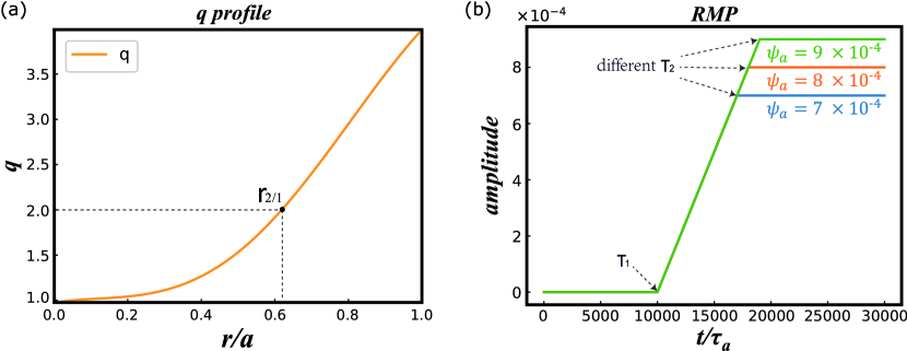
In this work, the plasma rotation is considered by setting , where is the plasma rotation frequency on the magnetic axis. The initial profiles of safety factor is shown in figure 1(a), in which the = 2/1 tearing mode without bootstrap current is stable (). The effect of RMP with is taken into account by the boundary condition
| (6) |
The time-dependent RMP in equation (6) is set as
| (7) |
where is the time when turning on the RMP, and is the growth rate of the RMP. In our simulation, we keep the growth rate of the RMP as a constant and modulate the amplitude of RMP by changing the flattop value of RMP as figure 1(b) illustrated. It should be pointed out that, in a real tokamak, the toroidal rotation is prevailing and much stronger than the poloidal one, whereas only the poloidal rotation is considered in this work due to the large aspect ratio approximation. The electromagnetic force exerted in the poloidal direction is times larger than that in toroidal direction, and the speed in toroidal direction should be times larger than the poloidal one for having an equivalent rotation frequency. Therefore, the locking threshold in the toroidal direction can be estimated by multiplying such a factor .

3 Numerical results
3.1 Effects of RMP amplitude
For a comprehensive understanding of the effects of RMP on NTMs, the effects of different RMP amplitudes on NTMs are investigated in this section. The common parameters are set as , , , and . The nonlinear evolution of NTM without RMP is given in figure 2 as a baseline case. It is seen in figure 2(a) that the magnetic island saturates at around and the saturate island width is about 0.2. During the whole evolution, the average island width is 0.206.
Firstly, a small bootstrap current fraction is taken into account. Figure 2(b) gives the average island widths in the presence of different RMP amplitudes. It is found that with the increase of RMP value, first decreases, indicating a stabilizing effect of RMP. However, once exceeds a threshold, immediately increases again. The processes associated with the relation between and can be divided into three regimes, which are illustrated in figure 3 and discussed in detail as follows.
-
1.
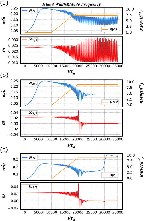
Slight suppression regime: when the RMP is turned on at , the island width and the mode frequency start to oscillate due to the electromagnetic torque applied by the boundary magnetic perturbation. As a result, the NTM can be slightly stabilized for a low , such as .
-
2.
Small locked island regime: for a moderate RMP, the NTM can be further stabilized and the island width is reduced to 0.13. The mode frequency drops slowly and then is suddenly locked to the RMP when the plasma rotation has been reduced to one half of its original value.
-
3.
Big locked island regime: for a sufficiently large RMP, the field penetration occurs accompanied with an explosive growth of island width, and the mode frequency is locked to the static magnetic field, which is known as the so-called locked mode.
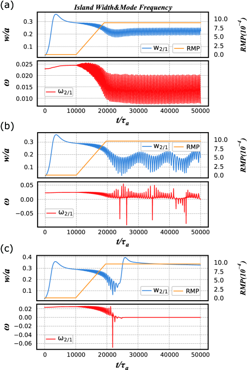
Secondly for a higher bootstrap current fraction, however, the regimes determined by different RMP amplitudes are different. As shown in figure 4, there are also three typical regimes for : (i) slight suppression regime; (ii) oscillation regime; (iii) big locked island regime. Although the (i) and (iii) regimes are almost the same as those of , a new oscillation regime (ii) appears instead of the small locked island regime (ii) of .
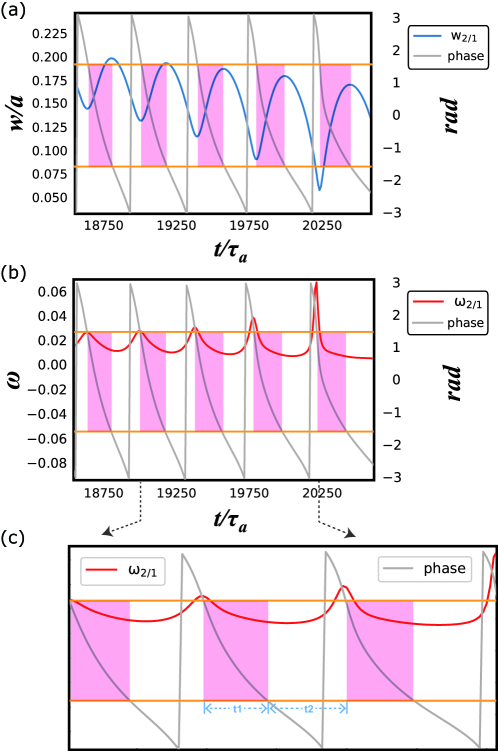
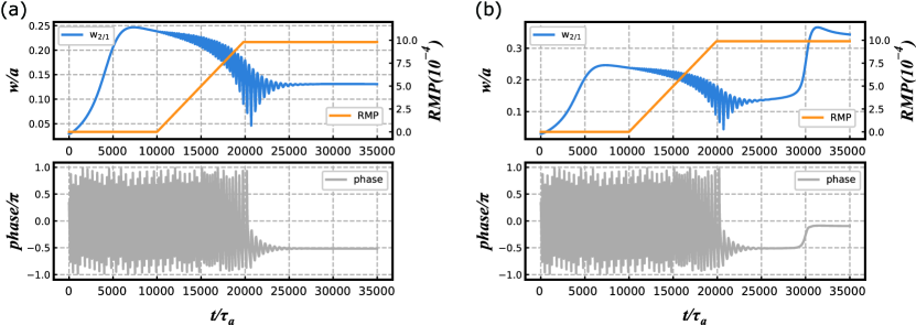
To understand the effects of RMP on NTM deeply, phase analysis has been carried out. Figure 5 gives the phase of the NTM, the island width and the mode frequency in the early suppression period, which can be observed in all regimes mentioned above. The phase of NTM is equal to the phase difference between the NTM and the RMP, since the phase of the static RMP is zero. In figures 5(a)(c), the gray line is the phase of NTM, the blue line is the island width, and the red line is the mode frequency. The yellow horizon lines are and respectively. When the phase difference is at (pink area), the RMP has a destabilizing effect on NTM. Oppositely, for (white area), the RMP has a stabilizing effect. Moreover, the mode frequency of the NTM also changes periodically. The RMP has a deceleration effect on the mode frequency when (pink area). For (white area), the RMP has an acceleration effect. It can be clearly noted in figure 5(c) that time interval in the white area is longer than in the pink area, leading to a net stabilizing effect on the island in an entire period. On the other hand, also indicates that the average mode frequency in the pink area is larger than that in the white area. As the amplitude of RMP gets higher, the electromagnetic torque becomes much bigger, which can be judged from the slopes of the mode frequency growth shown in figure 5. Once the electromagnetic force exceeds a threshold, the direction of the rotation can reverse. Then the mode can no longer travel through the whole phase region and the angular velocity is slowly damped, hence the SLI in the (ii) regime finally occurs, as shown in figure 6(a).
It should be noted in figures 6(a) and (b) that the phase of SLI is locked to 0.52, which is essentially different from the BLI regime where the phase is locked to 0.10 (almost the phase of the static RMP). For the SLI, the phase difference is in , where the RMP has a stabilizing effect on NTM. But for the BLI, the phase difference is in , where the RMP has a destabilizing effect on NTM. That is the reason why there are two kinds of locked mode with significantly different island widths for SLI and BLI.
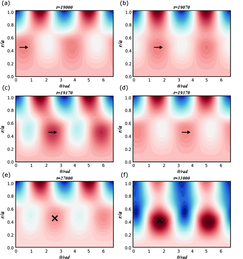
Figure 7 shows the evolution of the perturbed magnetic flux of BLI in figure 6(b). Figures 7(a)(d) give continuous motion slices of perturbed magnetic flux in one entire phase period. It can be found that when the NTM and the RMP are in the same phase, the RMP can enhance the magnetic reconnection, as shown in figures 7(b) and (c). But when they are in anti-phase, the RMP can prevent the magnetic reconnection, as shown in figures 7(a) and (d). Hence the magnetic island width periodically changes while the mode is rotating. Then the SLI occurs at about , and the island width is still small, as shown in figure 7(e), in which the NTM is static in the anti-phase of the RMP. But during , as shown in figure 7(f), the NTM is dragged to the same phase of the RMP by the electromagnetic torque, which leads to an explosive growth of the island width due to the continuous strong magnetic reconnection by the RMP.
3.2 The dependence of critical value of LM and plasma parameters
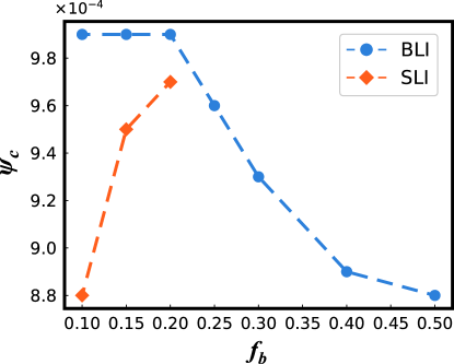
In this section, we analyze the critical RMP values in both SLI and BLI cases. Figure 8 shows the critical value versus , where the blue and yellow lines represent the critical values for BLI and SLI, respectively.
The of BLI decreases with the increase of due to the destabilizing effect of the bootstrap current. Since for a larger , the NTM becomes more unstable and the island width becomes larger, so that a lower RMP value is needed to lock the NTM. Interestingly, it is noticed that the of SLI increases with the increase of .
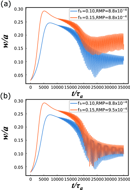
To make clear the dependence difference, the nonlinear evolution of magnetic island widths are compared for different values. In figure 9(a), it can be seen that for the same RMP amplitude of , the case of is still in the slight suppression regime, while the case of enters the SLI regime. Here for , is the critical value of SLI, as shown in figure 8. Figure 9(b) gives the evolution of the island widths for , and , . For , is the critical value of SLI, as shown in figure 8.
It is found that when SLI occurs, the island width of is suppressed to almost the same level as that of the . In our simulations, the island widths of SLI are found to be always around 0.1. It is revealed that for triggering a SLI, the island width should be small enough, indicating the existence of the critical value of the NTM island width. The correspondence existence of SLI in the classical TM has been identified in simulations and J-TEXT experiments[25]. Because a larger RMP value is required to suppress the island width to a small level, the critical value of SLI increases with the increase of . For an even larger , however, the BLI has occurred before the island width is suppressed to the level for triggering the SLI. Finally, the SLI disappears with the increase of , and thus only BLI remains.
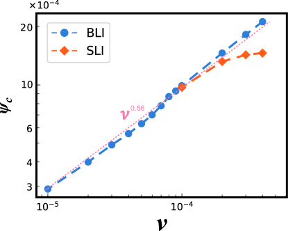
Dependence of critical value of locked mode on plasma viscosity is discussed, since the plasma viscosity is a key parameter affecting the mode locking. Figure 10 gives versus plasma viscosity . It is seen that for both BLI and SLI, increases with the increase of . It is reasonable that the large viscosity denotes a large viscous torque, which can balance the electromagnetic torque. Therefore, a larger electromagnetic force generated by RMP is needed to lock the NTM in the large viscosity region. Besides, it is noted that the SLI appears only in the large viscosity region. On the other hand, the scaling of the BLI with viscosity is numerically obtained as , which is very close to the theoretical one [35].
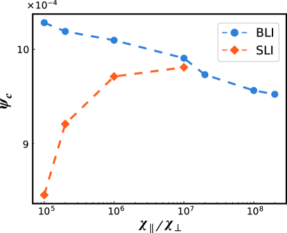
Figure 11 illustrates versus the ratio of parallel to perpendicular transport coefficient , since is very important for determining the saturated width of NTM island. Because the increase of normally increases the saturated island width, of BLI decreases. On the other hand, the SLI can only appear in the small region. In fact, the effect of on is similar to that of bootstrap current fraction shown in figure 8. Finally, it is indicated in figures 8,10 and 11 that the SLI tends to occur, when the NTM is in less unstable regimes.
4 Summary
In summary, the effects of externally applied static RMP on LM of NTM are numerically investigated by means of a set of reduced magnetohydrodynamic equations. A small locked island (SLI) regime and a big locked island (BLI) regime are discovered. Effects of some significant plasma parameters on the properties of the SLI and BLI are analyzed in detail. The main results can be summarized as follows.
-
1.
For the NTM with a small bootstrap current fraction , three regimes, namely slight suppression regime, SLI regime and BLI regime, are found with the increase of RMP amplitude. In the case with a low RMP amplitude, the NTM can be always stabilized. With the increase of RMP strength, two kinds of locked mode with qualitatively different properties are observed. In the SLI/BLI regime, the stabilized/destabilized islands of NTMs are locked to the RMP with phase difference being greater/less than .
-
2.
For the NTM with a large bootstrap current fraction , islands of NTM can be slightly suppressed with a low RMP amplitude, which is the same as the result in the small case. However, for a moderate RMP amplitude, an oscillating regime appears instead of the SLI regime. For a sufficiently large RMP amplitude, the BLI occurs. Thus, there are also three regimes, namely sight suppression regime, oscillation regime and BLI regime.
-
3.
Dependence of the critical value of RMP for BLI and SLI on the bootstrap current fraction , plasma viscosity , and the ratio of parallel to perpendicular transport coefficient are further discussed. It is found that the of BLI decreases as increases, since the electromagnetic force is proportional to the amplitude of the NTM which increases with the increase of . However, the of SLI unexpectedly increases with the increase of . This is due to the fact that, in this work, there is a critical value of island width for SLI, a higher RMP strength is needed to suppress the NTM to a necessarily small amplitude to trigger the SLI. For plasma viscosity , of both SLI and BLI increase with the increase of , since the viscous torque, to a great extent, can balance the electromagnetic torque. And only in the large region, the SLI occurs. Finally, like the effects of , the of BLI/SLI decreases/increases with the increase of . The SLI can only be found in the small region. It is found through the above results that SLI tends to occur when the NTM is in less unstable regimes.
Acknowledgements
The author W. Tang is indebted to Dr. Q. Yu for helpful discussions. Useful code benchmark work with T. Hender is greatly appreciated. The authors also acknowledge the Supercomputer Center of Dalian University of Technology for providing computing resources. This work was supported by the National Key R&D Program of China (Nos. 2017YFE0301900 and 2017YFE0301100), National Natural Science Foundation of China (No. 11675083), the Fundamental Research Funds for the Central Universities (Nos. DUT18ZD101 and DUT17LK38), and the Dalian Youth Science and Technology Project Support Program (No. 2015R01).
References
References
- [1] ITER 1999 Nucl. Fusion 39 2137
- [2] Hender T C et al 2007 Nucl. Fusion 47 S128
- [3] Maraschek M 2012 Nucl. Fusion 52 074007
- [4] Gorelenkov N N et al 1996 Phys. Plasmas 3 3379
- [5] Wang W et al 2018 Plasma Sci. Technol. 20 075101
- [6] Zohm H 1996 Plasma Phys. Control. Fusion 38 105
- [7] Zhao N et al 2018 Plasma Sci. Technol. 20 024007
- [8] Evans T E et al 2006 Nat. Phys. 2 419
- [9] Cai H S et al 2018 Nucl. Fusion 58 036008
- [10] Wei L and Wang Z X 2014 Nucl. Fusion 54 043015
- [11] Yang S X et al 2018 Nucl. Fusion 58 046016
- [12] Han M K et al 2017 Nucl. Fusion 57 046019
- [13] Chen W et al 2010 Nucl. Fusion 50 084008
- [14] Kikuchi M and Azumi M 2012 Rev. Mod. Phys. 84 1807
- [15] La Haye R J et al 2000 Phys. Plasmas 7 3349
- [16] Gao X et al 2015 Plasma Sci. Technol. 17 448
- [17] Gong X Z et al 2017 Plasma Sci. Technol. 19 032001
- [18] Sun Y W et al 2016 Phys. Rev. Lett. 117 115001
- [19] Nishimura S et al 2010 Plasma Fusion Res. 5 040
- [20] Hu Q M and Yu Q Q 2016 Nucl. Fusion 56 034001
- [21] Wang J L, Wang Z X and Wei L 2015 Phys. Plasmas 22 092122
- [22] Volpe F A et al 2015 Phys. Rev. Lett. 115 175002
- [23] Hender T C et al 1992 Nucl. Fusion 32 2091
- [24] Yu Q Q, Gnter S and Lackner K 2000 Phys. Rev. Lett. 85 2949
- [25] Hu Q M et al 2012 Nucl. Fusion 52 083011
- [26] Hu Q M et al 2013 Phys. Plasmas 20 092502
- [27] Yu Q Q, Gnter S and Lackner K 2018 Nucl. Fusion 58 054003
- [28] Wang X G et al 2015 Nucl. Fusion 55 093024
- [29] Choi W et al 2018 Nucl. Fusion 58 036022
- [30] Nave M F F and Wesson J A 1990 Nucl. Fusion 30 2575
- [31] Yu Q Q and Gnter S et al 2008 Nucl. Fusion 48 065004
- [32] Yu Q Q et al 2008 Nucl. Fusion 48 024007
- [33] Sun Y W et al 2010 Plasma Phys. Control. Fusion 52 105007
- [34] Fitzpatrick R 2015 Phys. Plasmas 22 042514
- [35] Fitzpatrick R 2003 Phys. Plasmas 10 1782
- [36] Fitzpatrick R 1998 Phys. Plasmas 5 3325
- [37] Hazeltine R D, Kotschenreuther M and Morrison P J 1985Phys. Fluids 28 2466
- [38] Strauss H R 1976 Phys. Fluids 19 134
- [39] Yu Q Q and Gnter S 1998 Phys. Plasmas 5 3924
- [40] Liu T et al 2018 Nucl. Fusion 58 076026
- [41] Ishii Y, Azumi M and Kishimoto Y 2002 Phys. Rev. Lett. 89 205002
- [42] Bierwage A et al 2005 Phys. Rev. Lett. 94 065001
- [43] Wang Z X, Wei L and Yu F et al 2015 Nucl. Fusion 55 043005
- [44] Wei L et al 2016 Nucl. Fusion 56 106015
- [45] Wang J L et al 2017 Nucl. Fusion 57 046007
- [46] Sato M and Wakatani M 2005 Nucl. Fusion 45 143