Electronic Structure of Single-Twist Trilayer Graphene
Abstract
Small-twist-angle bilayer graphene supports strongly correlated insulating states and superconductivity. Twisted few-layer graphene systems are likely to open up new directions for strong correlation physics in moiré superlattices. We derive and study moiré band models that describe the electronic structure of graphene trilayers in which one of the three layers is twisted by a small angle relative to perfect AAA, ABA, or ABC stacking arrangements. We find that the electronic structure depends very strongly on the starting stackings arrangement and on which layer is twisted. We identify ABA stacking with a middle-layer twist as a promising system for itinerant electron magnetism or even more robust superconductivity, because it exhibits both large and small velocity bands at energies near the Fermi level.
Introduction.—A small relative twist between van der Waals layers produces a long-wavelength moiré pattern (Liu et al., 2014; Cao et al., 2016; Kim et al., 2017; Li et al., 2010; Cao et al., 2018a, b; Chen et al., 2016; Zuo et al., 2018). Recently moiré superlattice systems have been realized experimentally in a number of two-dimensional layered materials, including graphene and transition metal dichalcogenides thanks to relatively weak interlayer interaction. Surprisingly, twisting layers to produce moiré patterns has turned out to be a powerful platform for creating and designing exotic electronic states, including ones with non-trivial band topology (Tong et al., 2016; Wu et al., 2017), unconventional superconductivity (Cao et al., 2018b), bands of interlayer and intralayer excitons (Yu et al., 2015; Wu et al., 2017) and magnetization (Thomson et al., 2018; Wu et al., 2018a). For the specific case of twisted bilayer graphene (TBG), vanishing renormalized Dirac velocities and flat electronic bands have been predicted at a series of small magic twist angles (Bistritzer and MacDonald, 2011). Magic angle bilayer systems exhibit Mott insulating phases and superconductivity(Cao et al., 2018b, a), and it is natural to expect modified but related behavior in all graphene multilayers when twists are present. The electronic structure of twisted trilayer graphene (TTG), for example, has been addressed in recent studies which focused on band topology, band evolution, and optical properties, among other quantities.(Correa et al., 2013; Suárez Morell et al., 2013; Qiao and He, 2014; Zuo et al., 2018; Amorim and Castro, 2018; Liu and Dai, 2019; Ma et al., 2019; Mora et al., 2019). We focus here on a relatively simple case, twisted trilayer graphene (TTG), with a twist in one layer only, which has not been investigated systematically. Single-twist TTG systems are distinguished by the starting crystalline stacking arrangement, and by which layer of the three layers is twisted.(Aoki and Amawashi, 2007; Bao et al., 2017). The new features present in the trilayer system have generalizations to thicker multi-layer stacks.
In this paper, we study the electronic properties of TTGs devices in which one of the three layers is twisted through a small angle relative to perfect ABA, ABC or AAA stacked structures, using a continuum moiré Hamiltonian. We demonstrate that different single-twist TTG structures have quite different electronic structures. This property is in contrast to TBG, in which top-layer and bottom-layer twists relative to AB, AA or BA stacking [See Fig. 1(a)] all lead to equivalent structures. More interestingly, ABA-stacked TTG with a twist in the middle layer exhibit flat bands at twist angles that are larger than for TBG and, because of mirror symmetry with respect to the middle layer, supports both large and small velocity bands near the Fermi level, Both the number and the value of magic angles increase with the number of layers in twisted few-layer graphene. These exotic characteristics identify twisted graphene layers with mirror symmetry as a promising system in which to seek new strong correlation physics.
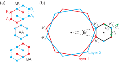
Methods.—We address the electronic structures of TTG devices using a continuum model and a plane-wave expansion for the bilayer’s four-component envelope function spinors. When only one layer is twisted, whether in the middle or on the outside, the low-energy effective Hamiltonian is periodic and can be solved using Bloch’s theorem. (In general the trilayer structure is incommensurateMora et al. (2019); Shi et al. (2019).) We choose the first Brillouin zone (BZ) shown in Fig. 1(b). For two monolayers with a small twist angle , the moiré BZ can be constructed from two monolayers’ BZs. The monolayer BZs’ neighboring corners, and , where the low-energy Dirac cones of the isolated layers are located, form two vertices of the moiré BZ. The length of the reciprocal lattice vector of the moiré pattern, , is therefore related to that of graphene, , by . When we assume the first graphene layer is on top of the second layer in Fig. 1(b) and add a third layer under the second layer, the third layer’s BZ coincides with the first (second) layer’s for a middle (top) layer twist and the moiré BZ is still given by Fig. 1(b).
Adding tunneling between neighboring layers to the isolated layer’s Dirac Hamiltonians leads to the following effective model of TTG ( projected to the valley):
| (1) |
Here, is the spin-independent Dirac Hamiltonian of the th layer accounting for its orientation: , where m/s, and are respectively the Fermi velocity of pristine graphene, a two-dimensional momentum, and the sublattice-pseudospin Pauli matrices. The angles, , and for middle-layer and top-layer twists. The interlayer tunneling terms are functions of spatial position, , and have the periodicity of the moiré pattern. In the middle-layer twist case, and . In the top-layer twist case, is independent of position. Here is the tunneling energy which we set to 124.5 meV to match infrared spectroscopy measurements (Kuzmenko et al., 2009) and the are the inter-layer tunneling momentum boosts, and (Bistritzer and MacDonald, 2011). The matrices account for the sublattice dependence of tunneling and depend on bilayer stacking:
| (2) |
where AB, AA and BA refer to the stacking arrangements illustrated in Fig. 1. By using the appropriate matrices for tunneling between adjacent layers, we can describe ABA, ABC and AAA TTG.
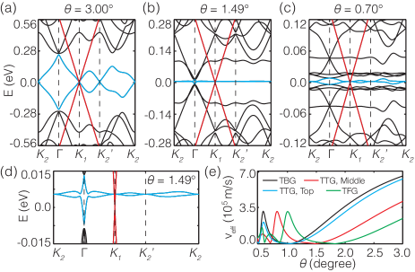
Results.— We first discuss the band structures of TTG with a middle-layer twist relative to ABA stacking, which is illustrated in Fig. 2. The top-layer twist case and some other stacking arrangements are discussed later for comparison. In Fig. 2, three representative twist angles are chosen to illustrate how the moiré bands evolve with twist. At a large twist angle (3.0°), we see two distinct gapless Dirac cones with different Fermi velocities at the band crossing momentum point, . The Dirac cone with the larger Fermi velocity maintains linear dispersion in the illustrated 1.0 eV energy range. One can check that its Fermi velocity is equal to that of an isolated graphene layer, m/s. In contrast, the other Dirac cone is linear only over several tens meV [See Fig. 2 (a)] and its dispersion is evidently altered by moiré pattern. The avoided crossing at the midpoint of produces a characteristic van Hove singularity (Bistritzer and MacDonald, 2011; Li et al., 2010; Kim et al., 2017). As the angle decreases, the high-velocity Dirac cone is still undisturbed while the small-velocity Dirac cones at and become shallower, reaching velocities smaller than 200 m/s at 1.49∘. The low-energy moiré bands becomes very flat near this magic angle, reaching a minimum bandwidth of meV due mostly to dispersion near . Fig. 2 (b,d)]. At smaller angles, the renormalized velocity varies continuously, with more emergent magic angles [Red line in Fig. 2 (e)]. It is seen that a second magic angle appears at 0.70°, with the vanishing velocity and nearly flat bands [Fig. 2 (c)].
The moiré band structures of TTG devices have two main characteristics that distinguish them from bilayers: (i) The magic angles are larger by a factor of about 1.4. For TBG, the first two magic angle are 1.05° and 0.50°(Bistritzer and MacDonald, 2011). [Fig. 2 (e)]. Larger angles will make it easier to locate the magic angles and study their exotic electronic properties (Cao et al., 2018a, b; Wu et al., 2018b; Song et al., 2018). (ii) In stacks with mirror symmetry there is, in addition to flat bands, one band with an undisturbed single-layer Dirac cone at all twist angles. The simultaneous presence of both large and small velocity bands in a moiré superlattice opens up new opportunities for quantum simulation because of its similarity to circumstances that often arise in atomic-scale crystals, for example in elemental transition metals, in which extended and localized orbitals are present in the same energy range.
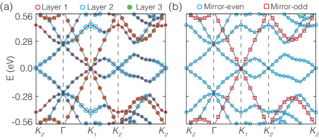
To better understand the band structures of ABA middle-layer twist TTG devices, we plot the layer projection weights of band eigenstates in Fig. 3 (a). It is seen that the high-velocity Dirac cone states are on the outmost layers and have no middle layer component. In contrast, all weight is present in all three layers for the flatter bands, implying entanglement between the middle and outside layers. The outmost layer weights are always identical. These features can be understood in terms of the mirror symmetry of ABA stacking with respect to the middle layer. At any twist angle, electronic states are all eigenstates of the mirror operator. Fig. 3 (b) shows the mirror symmetry for each electronic state. The high-velocity Dirac cones are mirror-antisymmetric, that is, the wavefunction is odd when swapping two outmost layers. In the antisymmetric state, the coupling from the two outside to the middle layer interferes destructively. On the other hand, the flatter bands are symmetric and their wavefuctions are unchanged under the the mirror operation.
It is useful to examine the lowest-order truncation(Bistritzer and MacDonald, 2011) of the plane-wave expansion(Bistritzer and MacDonald, 2011), which allows some analytic progress by including only one Dirac cone on the outmost layers coupled to the three nearest Dirac states of the middle layer:
| (3) |
Here, ignores the small twist. The corresponding wavefunction is defined as , where , and are sublattice spinors on the three layers. Treating the coupling to the middle layer states, which have finite energy at , perturbatively and using the identity (Bistritzer and MacDonald, 2011), we find four zero energy states at with . The dispersion at small can then be found by diagonalizing in the zero-energy subspace. Reflecting the problem’s mirror symmetries the low-energy Hamiltonian is diagonalized by , corresponding to mirror-symmetric and antisymmetric states. For , the low-energy dispersion,
| (4) |
The effective Fermi velocity, , after the renormalization is therefore , which depends on only one parameter . The magic angle condition is therefore ,; at this value of the expectation values of the velocity operators cancel between the outmost layers and the middle layer. The magic angle of TTG is time larger than that of TBG (Bistritzer and MacDonald, 2011). The simple model captures the increase of the magic angle of TTG compared to TBG. The small-velocity bands act like an effective TBG system because the outmost layers act as a single layer. The hopping energy becomes larger by a factor of due to constructive interference. The enhanced is due to presence of more tunneling processes between the middle layer and in-phase outmost layers. For , and . Because the middle layer is absent in the mirror odd sector, only the outmost layers contribute to the undisturbed Dirac cone. The flat bands with larger magic angles and the high-velocity Dirac cone therefore respectively arise from the mirror-even and mirror-odd electronic sectors. The simple model agrees with the band projections in Fig. 3 and explains the main characteristics in the electronic structures of middle-layer twist ABA TTG.
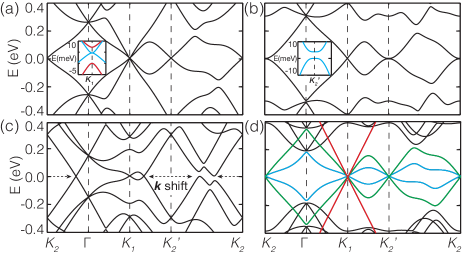
For TTG with a middle-layer twist, we also consider other starting stacking arrangements. Fig. 4 (a) shows the band structure that emerges from ABC stacking for middle layer twists. In this case mirror symmetry is absent. There are two Dirac cones with different low-energy behaviors at , as in the ABA case. One Dirac cone (blue bands in inset) has a reduced, but still sizable, Fermi velocity which reaches a minimum of m/s at 1.52°. The other Dirac cone (red) is, in contrast to the ABA-stacked TTG case, gapped at .
We have also studied top-layer twist cases, which never have mirror symmetry. Figs. 4 (b) and (c) respectively show the moiré band structures for ABA and AAA stacking with a top layer twist. For ABA stacking with a top layer twist, there are a Dirac cone at and a parabolic band at in the low-energy range, which at large twist angles have layer projections mainly on to the top layer and the bottom bilayer respectively. This is expected given that and are respectively BZ corners of top layer and bottom bilayer. The parabolic bands are gapped [See the inset in Fig. 4(b)], unlike the bands of an isolated BA-stacked bilayer (Partoens and Peeters, 2006), because the top layer adds a vertical potential to the bilayer (Castro et al., 2007). The bandgap opening may provider opportunities for valley-contrasting optoelectronics in twisted graphene systems (Xiao et al., 2007; Yao et al., 2008; Zhu et al., 2018). Moreover, the low-energy bands become flat at magic angles equal to ones of TBG [Fig. 2(e)], agreeing with previous results (Suárez Morell et al., 2013) . For AAA-stacked TTG with a twist in the top layer, the AA-stacked bottom bilayer mainly contributes to low-energy bands that are centered at but have a sizable momentum shift from , similar to that of an isolated AA-stacked bilayer (de Andres et al., 2008). The momentum differences between Dirac cone at and low-energy bands around are no longer equal to , and interlayer tunnelings between these states are suppressed. Flat bands and vanishing velocities are therefore not found for this stacking.
Discussion— When one layer is twisted relative to another, TBG forms a moiré superlattice in which regions with local AA, AB and BA stacking form three offset triangular lattices. The stacking (for example AA, AB or BA) prior to the twist changes the twist axis but otherwise lead to the same moiré pattern. Indeed, the electronic properties of TBG are independent of the original stacking (Bistritzer and MacDonald, 2011; Wu et al., 2018b). Any graphene multilayer with more than two layers also forms a periodic moiré superlattice when one layer, or one subset of layers, is rotated relative to the other layers. Each is characterized by a spatially varying local multilayer stacking arrangement which varies periodically in space. Focusing on the trilayer case, we have demonstrated that a wide variety of different behaviors result from small twists, depending on the original stacking order and on which layer is twisted. In the multilayer case, the moiré supperlattice electronic properties vary widely even for the same twist angle. It is because different original stacking orders and twist layers result in different moiré patterns that determine electronic properties. That is, the moiré superlattice of the TTG, as well as twisted few-layer graphene, has no longer one pattern, distinct from that of TBG. In particular, moiré patterns with and without mirror symmetry demonstrate starkly different electronic properties. Moreover, for a middle-layer twist, local ABA and AAA stackings coexist in the moiré pattern with mirror symmetry. Therefore, the TTG formed by a rotation relative to AAA stacking has the same geometrical and electronic structures with the ABA-stacked TTG, as shown in Fig. 2. The same applies to ABC and BAA stackings that both appear in the moiré pattern without mirror symmetry. Similarly, for a top-layer twist, BBA- and BAA-stacked TTGs have the same electronic structures with ABA- and AAA-stacked ones, respectively.
Compared with TBG, the magic angles in a mirror-protected TTG increase by a factor of . This increase can be enhanced by increasing the thickness of the stacks. We computed the electronic structure of twisted five-layer graphene (TFG) structures starting from ABABA Bernal stacking and rotating even-numbered layers relative to odd-numbered layers. In this case the middle layer is a mirror plane. As shown in Fig. 4 (d), there are two low-velocity Dirac cones at (blue and green bands) with velocity renormalization and one undisturbed Dirac cone (red) with the same velocity as an isolated graphene layer. The two modified Dirac cones yield two groups of magic angles, one larger by a factor of yielding a largest magic angle of 1.82°, as illustrated in Fig. 2 (e), and another set of magic angles equal to those of TBG. The possibility of larger magic angles and the coexistence between flat bands and undisturbed Dirac cones occur in mirror-protected TFG, just as in like TTG. These electronic properties are well explained by the truncated Hamiltonians like Eq. 3 (See details in Appendix A). The larger magic angles arise from the coherent enhancement of stacked TBGs in a mirror-even eigenstate, similar to TTG. Similarly twisted seven-layer graphene is computed to have two magic angles larger than 1°, at 1.49° and 1.94°. For twisted nine-layer, the magic angles larger than 1° are 1.24°, 1.70° and 2.00°.
The possibility of more and larger magic angles in twisted few-layer graphenes provides a powerful motivation for fabricating and characterizing these multilayer devices to explore their flat-band-related physics. The coexistence of small and large velocity bands in TTG with mirror symmetry could have important implications for superconductivity when effective interactions between quasiparticles are attractive, and for itinerant electron magnetism when effective interactions between quasiparticles are repulsive. In the superconducting case the undisturbed Dirac cone with high velocity could lead to enhanced superfluid stiffness and increases in the the Berezinskii-Kosterlitz-Thouless transition temperature. In the magnetic case, the high velocity band could stiffen magnons and again increase ordering temperatures. This exploratory theoretical work makes it clear that the study of many-body interaction effects in multilayer graphene moiré superlattices is still at an early stage.
Acknowledgements.
Acknowledgments X. L. is grateful to Bangguo Xiong for valuable discussions. A. M. is supported by the Welch Foundation under Grant No. TBF1473 and the Department of Energy under Grant No. DE-FG02-ER45118. X. L. is supported by the start-up funds from Nanjing Normal University and F. W. is supported by Laboratory for Physical Sciences.I Appendix A: The simplest model of twisted five-layer graphene
To investigate the origin of low-energy bands of twisted five-layer graphene in Fig. 4 (d), we extend the effective model in Eq. 3 and make the submatrix for the third-fifth layers equal to that for the first-third layers. We define the wavefuction as , where , , , and are spinors acting on the sublattices of the first to fifth layers, respectively. According to the relation , three wavefunction’s expressions for the zero-energy eigenvalues at are obtained with . They correspond to two low-velocity Dirac cones with the velocity renormalization and one undisturbed Dirac cone with isolated graphene’s Fermi velocity, as followings,
(i) A mirror-even wavefunction has and . The low-energy dispersion of the Dirac bands is then computed by the expectation value of , that is,
| (5) |
Therefore, the renormalized Fermi velocity . The magic angle appears at where . The angle increases by a factor of compared to TBG, due to coherent enhancement of stacked TBGs under the action of mirror symmetry.
(ii) A mirror-odd state corresponds to , and . The vanishing contribution from the middle layer isolates the top TBG (i.e. the first and second layers) and the bottom TBG (the fourth and fifth layers). In a similar way as the above wavefunction, the calculated Fermi velocity, , according to the expectation value of . The corresponding magic angle appears at , which is equal to that of TBG.
(iii) The other mirror-even state gives and . Similar to the above solution, the absence of the second and fourth layers’ components separate three odd-numbered monolayers, leading to isolated graphene’s Dirac cone.
References
- Liu et al. (2014) K. Liu, L. Zhang, T. Cao, C. Jin, D. Qiu, Q. Zhou, A. Zettl, P. Yang, S. G. Louie, and F. Wang, Nat. Commun. 5, 4966 (2014).
- Cao et al. (2016) Y. Cao, J. Y. Luo, V. Fatemi, S. Fang, J. D. Sanchez-Yamagishi, K. Watanabe, T. Taniguchi, E. Kaxiras, and P. Jarillo-Herrero, Phys. Rev. Lett. 117, 116804 (2016).
- Kim et al. (2017) K. Kim, A. DaSilva, S. Huang, B. Fallahazad, S. Larentis, T. Taniguchi, K. Watanabe, B. J. LeRoy, A. H. MacDonald, and E. Tutuc, PNAS 114, 3364 (2017).
- Li et al. (2010) G. Li, A. Luican, J. L. Dos Santos, A. C. Neto, A. Reina, J. Kong, and E. Andrei, Nature Physics 6, 109 (2010).
- Cao et al. (2018a) Y. Cao, V. Fatemi, A. Demir, S. Fang, S. L. Tomarken, J. Y. Luo, J. D. Sanchez-Yamagishi, K. Watanabe, T. Taniguchi, E. Kaxiras, et al., Nature 556, 80 (2018a).
- Cao et al. (2018b) Y. Cao, V. Fatemi, S. Fang, K. Watanabe, T. Taniguchi, E. Kaxiras, and P. Jarillo-Herrero, Nature 556, 43 (2018b).
- Chen et al. (2016) X.-D. Chen, W. Xin, W.-S. Jiang, Z.-B. Liu, Y. Chen, and J.-G. Tian, Adv. Mater. 28, 2563 (2016).
- Zuo et al. (2018) W.-J. Zuo, J.-B. Qiao, D.-L. Ma, L.-J. Yin, G. Sun, J.-Y. Zhang, L.-Y. Guan, and L. He, Phys. Rev. B 97, 035440 (2018).
- Tong et al. (2016) Q. Tong, H. Yu, Q. Zhu, Y. Wang, X. Xu, and W. Yao, Nat. Phys. 13, 356 (2016).
- Wu et al. (2017) F. Wu, T. Lovorn, and A. H. MacDonald, Phys. Rev. Lett. 118, 147401 (2017).
- Yu et al. (2015) H. Yu, Y. Wang, Q. Tong, X. Xu, and W. Yao, Phys. Rev. Lett. 115, 187002 (2015).
- Thomson et al. (2018) A. Thomson, S. Chatterjee, S. Sachdev, and M. S. Scheurer, Phys. Rev. B 98, 075109 (2018).
- Wu et al. (2018a) F. Wu, T. Lovorn, E. Tutuc, and A. H. MacDonald, Phys. Rev. Lett. 121, 026402 (2018a).
- Bistritzer and MacDonald (2011) R. Bistritzer and A. H. MacDonald, PNAS 108, 12233 (2011).
- Correa et al. (2013) J. D. Correa, M. Pacheco, and E. S. Morell, J. Mater. Sci. 49, 642 (2013).
- Suárez Morell et al. (2013) E. Suárez Morell, M. Pacheco, L. Chico, and L. Brey, Phys. Rev. B 87, 125414 (2013).
- Qiao and He (2014) J.-B. Qiao and L. He, Phys. Rev. B 90, 075410 (2014).
- Amorim and Castro (2018) B. Amorim and E. V. Castro, arXiv:1807.11909 (2018).
- Liu and Dai (2019) J. Liu and X. Dai, arXiv:1903.10419 (2019).
- Ma et al. (2019) Z. Ma, S. Li, Y.-W. Zheng, M.-M. Xiao, H. Jiang, J.-H. Gao, and X. Xie, arXiv:1905.00622 (2019).
- Mora et al. (2019) C. Mora, N. Regnault, and B. A. Bernevig, Phys. Rev. Lett. 123, 026402 (2019).
- Aoki and Amawashi (2007) M. Aoki and H. Amawashi, Solid State Commun. 142, 123 (2007).
- Bao et al. (2017) C. Bao, W. Yao, E. Wang, C. Chen, J. Avila, M. C. Asensio, and S. Zhou, Nano Lett. 17, 1564 (2017).
- Shi et al. (2019) J. Shi, J. Zhu, and A. H. MacDonald, In preparation (2019).
- Kuzmenko et al. (2009) A. B. Kuzmenko, I. Crassee, D. van der Marel, P. Blake, and K. S. Novoselov, Phys. Rev. B 80, 165406 (2009).
- Wu et al. (2018b) F. Wu, A. H. MacDonald, and I. Martin, arXiv:1805.08735 (2018b).
- Song et al. (2018) Z. Song, Z. Wang, W. Shi, G. Li, C. Fang, and B. A. Bernevig, arXiv:1807.10676 (2018).
- Partoens and Peeters (2006) B. Partoens and F. M. Peeters, Phys. Rev. B 74, 075404 (2006).
- Castro et al. (2007) E. V. Castro, K. S. Novoselov, S. V. Morozov, N. M. R. Peres, J. M. B. L. dos Santos, J. Nilsson, F. Guinea, A. K. Geim, and A. H. C. Neto, Phys. Rev. Lett. 99, 216802 (2007).
- Xiao et al. (2007) D. Xiao, W. Yao, and Q. Niu, Phys. Rev. Lett. 99, 236809 (2007).
- Yao et al. (2008) W. Yao, D. Xiao, and Q. Niu, Phys. Rev. B 77, 235406 (2008).
- Zhu et al. (2018) G.-Y. Zhu, T. Xiang, and G.-M. Zhang, arXiv:1806.07535 (2018).
- de Andres et al. (2008) P. L. de Andres, R. Ramírez, and J. A. Vergés, Phys. Rev. B 77, 045403 (2008).