Error-corrected gates on an encoded qubit
Abstract
To solve classically hard problems, quantum computers need to be resilient to the influence of noise and decoherence. In such a fault-tolerant quantum computer, noise-induced errors must be detected and corrected in real-time to prevent them from propagating between components Preskill (1998); Campbell et al. (2017). This requirement is especially pertinent while applying quantum gates, when the interaction between components can cause errors to quickly spread throughout the system. However, the large overhead involved in most fault-tolerant architectures Fowler et al. (2012); Campbell et al. (2017) makes implementing these systems a daunting task, which motivates the search for hardware-efficient alternatives Mirrahimi et al. (2014); Guillaud and Mirrahimi (2019). Here, we present a gate enacted by a multilevel ancilla transmon on a cavity-encoded logical qubit that is fault-tolerant with respect to decoherence in both the ancilla and the encoded qubit. We maintain the purity of the encoded qubit in the presence of ancilla errors by detecting those errors in real-time, and applying the appropriate corrections. We show a reduction of the logical gate error by a factor of two in the presence of naturally occurring decoherence, and demonstrate resilience against ancilla bit-flips and phase-flips by observing a sixfold suppression of the gate error with increased energy relaxation, and a fourfold suppression with increased dephasing noise. The results demonstrate that bosonic logical qubits can be controlled by error-prone ancilla qubits without inheriting the ancilla’s inferior performance. As such, error-corrected ancilla-enabled gates are an important step towards fully fault-tolerant processing of bosonic qubits.
In recent years, quantum error correction (QEC) has been demonstrated to protect stored logical qubits against decoherence, either by encoding the information redundantly in a block of multiple physical qubits Kelly et al. (2015); Nigg et al. (2014); Cramer et al. (2016); Córcoles et al. (2015), or in a single higher-dimensional bosonic element Ofek et al. (2016); Flühmann et al. (2019); Hu et al. (2019). The concept of fault-tolerant operations extends this principle to the protection of quantum information during a computation involving multiple elements. In particular, errors propagating between elements must not accumulate to the extent that the errors can no longer be removed by QEC. Each task performed in a quantum computer must eventually be made fault-tolerant, including syndrome measurements Rosenblum et al. (2018); Linke et al. (2017), state preparation Linke et al. (2017); Takita et al. (2017), and gates Harper and Flammia (2019). Remarkably, following this procedure can allow an error-corrected quantum processor to perform computations at any desired accuracy Aharonov and Ben-Or (2008).
Some quantum gates can be implemented in a way that is naturally protected by the encoding of choice, and do not require additional resources, e.g. braiding operations in the surface code Fowler et al. (2012), transversal operations in CSS codes Steane and Ibinson (2005), and displacements in GKP codes Gottesman et al. (2001). However, these “natural” operations are often insufficient to create a universal gate set Eastin and Knill (2009); Webster and Bartlett (2018). One method of addressing this shortcoming is to “inject” additional gates by coupling to an ancilla qubit that has more complete functionality Bravyi and Kitaev (2005); Zhou et al. (2000). These ancilla-based operations are not native to the encoding, and as such, require a significant overhead in hardware and number of operations to implement fault-tolerantly Fowler et al. (2012); Campbell et al. (2017).
Here, we devise a hardware-efficient circuit that uses a driven ancilla qubit to apply protected gates to a logical qubit encoded in a bosonic mode. Our scheme works by encoding the ancilla in a single multilevel system as well, and using this freedom to identify and correct errors occurring during the gate operation. Remarkably, by employing the information obtained in the final ancilla measurement, we can recover the logical qubit, and reapply the gate if necessary.
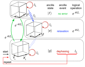
The principal mechanism underlying the gate’s fault-tolerance is path-independence Ma et al. (2019)—the property that, given fixed initial and final ancilla states, the net logical operation is independent of the specific ancilla trajectory induced by control drives and decoherence events (Figure 1). Path-independence requires that we drive the ancilla in such a way that its populations do not depend on the state of the logical system. In order to ensure that the evolution of the logical qubit under the effect of decoherence is a fixed unitary, our circuit uses an error-transparent interaction Kapit (2018); Rosenblum et al. (2018) to couple the ancilla and qubit.
We implement our logical qubit using a single bosonic mode in a superconducting cavity (Fig. 2a, Supplementary Information section 8). Within this mode, quantum information is stored in the subspace defined by the binomial “kitten” code Michael et al. (2016), which, like the Schrödinger cat code Mirrahimi et al. (2014), can correct for the loss of a single photon. The logical states can be represented in the photon number basis as and . We implement a family of operations , which are rotations by any angle around the axis in the logical subspace (Fig. 2b), using the selective number-dependent arbitrary phase (SNAP) protocol Krastanov et al. (2015); Heeres et al. (2015). This protocol drives a dispersively coupled transmon ancilla qubit to the excited state with a photon-number dependent phase. can be effected by choosing the phase of the control drive to be zero on photon number states and , and on . The arbitrary angle of rotation in allows the realization of logical Clifford operations (, with ) as well as non-Clifford operations such as the -gate (). This gate set can be combined with a single rotation around a different logical axis to provide universal control of the logical qubit.
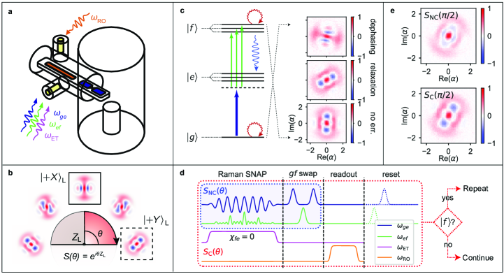
The ancilla undergoes two predominant types of errors: dephasing and energy relaxation. To correct the effects of these errors, we must first make them independently detectable. We do so by modifying the SNAP protocol to use three levels of the ancilla, instead of two. By driving a Raman transition (Fig. 2c, Supplementary Information section 5) from the ground state () to the second excited state () with a photon-number dependent phase, we implement the SNAP operation while avoiding population of the first excited state (). Next, we swap and , so as to minimize the probability of ancilla relaxation during the subsequent ancilla state measurement (Fig. 2d). The measurement outcome determines which (if any) type of ancilla error occurred, as well as the operation effected on the cavity state.
We ensure protection against ancilla dephasing during the SNAP operation by simultaneously driving the ancilla to with equal rates for all photon number states in the logical subspace. Since the control drives have photon number dependent phases, the ancilla becomes entangled with the logical system. However, the ancilla population remains uncorrelated with the logical state during the driven evolution. Therefore, projecting the ancilla to or at any time during the protocol, as the environment does in the case of dephasing, does not impart any back-action on the logical state. However, dephasing events will create some probability of not successfully finishing the transit from to . By considering the effective Hamiltonian in the interaction picture during the operation (Supplementary Information section 1)
| (1) |
we can see that the logical action associated with going from to is the desired gate , whereas the logical action of going from to is the inverse operation . As a result, if the ancilla trajectory ends in ( following the final swap) due to a dephasing event, the net effect on the logical system is the identity operation. Remarkably, this path-independence ensures protection even against multiple dephasing events. We can ensure deterministic application of the gate in the presence of dephasing by resetting the ancilla and repeating the protocol upon measuring .
Energy relaxation during the application of the gate occurs predominantly through decay from to . The latter state remains unaffected under the action of the control drives, and therefore the final state should be detected as , assuming no further decay events. Since the trajectory taking the ancilla from to passes through (Fig. 1), the effective operation on the logical system is . However, the cavity state will also acquire a random phase space rotation (depending on the jump time) due to the static cavity-ancilla interaction , with the photon-number operator and the dispersive interaction rate in in a frame rotating with . This random rotation can be understood as the back-action induced by the emitted ancilla excitation carrying photon-number dependent energy. By using the detuned sideband driving scheme presented in Ref. Rosenblum et al. (2018), we can effectively set for the duration of the gate (Supplementary Information section 6). This “error-transparency” drive eliminates the random rotation imparted on the cavity state, thereby maintaining path-independence in the case of relaxation.
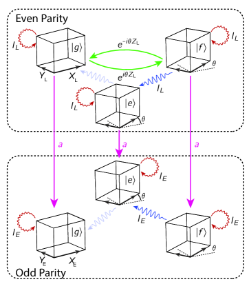
In addition to ancilla errors, the protocol is compatible with QEC protecting against photon loss in the cavity. Since the control drives do not act on the system in the odd photon number subspace, the result is equivalent to incomplete driving followed by photon loss. While not done in this work, applying a parity measurement Sun et al. (2014); Rosenblum et al. (2018) and recovery operation Michael et al. (2016) following the protocol, would make the effect of photon loss equivalent to that of ancilla dephasing (Supplementary Information section 3).
The key feature is that, regardless of the measured ancilla state, the cavity remains in a definite pure state contained within the logical subspace. To demonstrate this, we create Heeres et al. (2017) the state , apply the operation , and perform Wigner tomography (Fig. 2c). In this experiment, the error-transparency drive is applied, and the ancilla is measured without conditional repetition of the gate. The Wigner functions are shown separately for each measured ancilla state. In order to emphasize the effect of ancilla errors, we increase the ancilla error probability during this operation (Supplementary Information section 4), so that the probability of relaxation and dephasing errors are each. As expected, in the case of successful completion of the protocol (ancilla in ), or in the case of relaxation (ancilla in ), the gate is correctly applied. Different deterministic phase space rotations are acquired by the cavity for different final ancilla states, as a result of evolution during the ancilla measurement. This angle is corrected in software by updating the phase of subsequent drives around the cavity resonance frequency. Finally, in the case of ancilla dephasing (ancilla in ), we observe the initial logical state . The slight asymmetry is a result of the Kerr evolution, whose removal requires successful completion of the logical gate Heeres et al. (2015).
We next perform two versions of the full gate, the standard (non-corrected) gate and the error-corrected gate (Fig. 2d), again with increased ancilla error rates. We characterize the result via Wigner tomography without conditioning on the ancilla measurement outcome (Fig. 2e). In the case of the standard gate (), we observe significant smearing of the final state. However, in the case of the error-corrected gate (), which includes the error-transparency drive, ancilla measurement, reset, and conditional repetition, it is evident that, despite the high ancilla error rate, the cavity coherence is mostly preserved.
In order to establish the gate’s logical error probability quantitatively, we turn to interleaved randomized benchmarking (IRB) Magesan et al. (2012). We first create a set of operations from the logical Clifford group using numerical optimal control Heeres et al. (2017). We then interleave the gate between randomly selected Clifford operations, scanning the length of the sequence (Fig. 3a). We measure the probability of obtaining the correct answer in the ancilla after applying a decoding operation as a function of the sequence length (Fig. 3b), and compare the performance of and . The measured gate error probability for (obtained from the difference between the decay rates of the interleaved and the non-interleaved sequences) is . The main effect in producing this error probability is ancilla relaxation (, with an additional accounted for resulting from ancilla dephasing, photon loss, and thermal ancilla excitation. In contrast, the error-corrected gate has an error probability of . No single process dominates the remaining error, but a full accounting of the known sources, including photon loss, readout-induced dephasing, and other sources, predicts an error probability of 2.1% (Supplementary Information section 7).
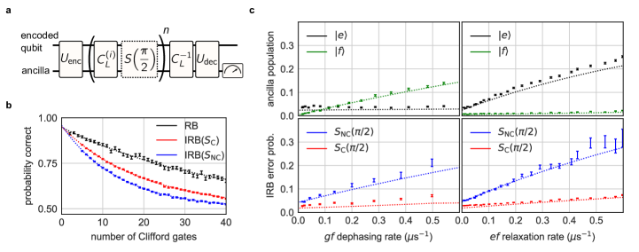
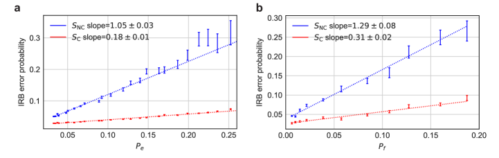
In order to demonstrate the robustness of the gate to ancilla decoherence, we intentionally introduce noise to increase the ancilla dephasing and relaxation rates (Supplementary Information section 4). We scan the induced dephasing rate and relaxation rates from their native rates of and , respectively, up to maximum rates of . The ancilla state probabilities vary as expected, with changing from 3.4% to 25% with increased relaxation rate and changing from 1% to 14% with increased dephasing rate (Fig. 3c). For , the induced gate error probability is nearly equal to the probability of measuring the ancilla in an excited state, indicating that ancilla errors are bound to propagate and affect the logical qubit. However, for , the ratio of gate errors to ancilla errors (Supplementary Information section 4) is suppressed by a factor of () for injected relaxation ( dephasing) errors, clearly demonstrating the resilience of the gate against ancilla errors.
We have presented an ancilla-enabled gate that uses the principle of path-independence to maintain coherence of the logical qubit in the presence of ancilla errors. We demonstrated that the error-correction suppresses the propagation of the dominant errors, namely relaxation and dephasing, from the ancilla to the logical system. The scheme is readily extended to protect against a broader class of ancilla errors, such as thermal excitation or multiple-decay events, by employing higher ancilla levels. Furthermore, we can incorporate protection against photon loss by performing a fault-tolerant parity measurement Rosenblum et al. (2018) after the gate, and using the result to perform QEC Ofek et al. (2016). We have demonstrated the feasibility of a hardware-efficient approach to protecting quantum information not only during storage, but also as it is being processed by quantum gates. Expanding these results to create additional error-corrected gates Xu et al. (2018); Gao et al. (2019), and therefore providing universal fault-tolerant control, is a promising path towards robust quantum computing devices.
References
- Preskill (1998) J. Preskill, in Introduction to Quantum Computation and Information (World Scientific, 1998) pp. 213–269.
- Campbell et al. (2017) E. T. Campbell, B. M. Terhal, and C. Vuillot, Nature 549, 172 (2017).
- Fowler et al. (2012) A. G. Fowler, M. Mariantoni, J. M. Martinis, and A. N. Cleland, Physical Review A 86, 032324 (2012).
- Mirrahimi et al. (2014) M. Mirrahimi, Z. Leghtas, V. V. Albert, S. Touzard, R. J. Schoelkopf, L. Jiang, and M. H. Devoret, New Journal of Physics 16, 045014 (2014).
- Guillaud and Mirrahimi (2019) J. Guillaud and M. Mirrahimi, Preprint at https://arXiv.org/abs/1904.09474 (2019).
- Kelly et al. (2015) J. Kelly, R. Barends, A. G. Fowler, A. Megrant, E. Jeffrey, T. C. White, D. Sank, J. Y. Mutus, B. Campbell, Y. Chen, Z. Chen, B. Chiaro, A. Dunsworth, I.-C. Hoi, C. Neill, P. J. J. O’Malley, C. Quintana, P. Roushan, A. Vainsencher, J. Wenner, A. N. Cleland, and J. M. Martinis, Nature 519, 66 (2015).
- Nigg et al. (2014) D. Nigg, M. Müller, E. A. Martinez, P. Schindler, M. Hennrich, T. Monz, M. A. Martin-Delgado, and R. Blatt, Science 345, 302 (2014).
- Cramer et al. (2016) J. Cramer, N. Kalb, M. A. Rol, B. Hensen, M. S. Blok, M. Markham, D. J. Twitchen, R. Hanson, and T. H. Taminiau, Nature Communications 7, 11526 (2016).
- Córcoles et al. (2015) A. Córcoles, E. Magesan, S. J. Srinivasan, A. W. Cross, M. Steffen, J. M. Gambetta, and J. M. Chow, Nature Communications 6, 6979 (2015).
- Ofek et al. (2016) N. Ofek, A. Petrenko, R. Heeres, P. Reinhold, Z. Leghtas, B. Vlastakis, Y. Liu, L. Frunzio, S. M. Girvin, L. Jiang, M. Mirrahimi, M. H. Devoret, and R. J. Schoelkopf, Nature 536, 441 (2016).
- Flühmann et al. (2019) C. Flühmann, T. L. Nguyen, M. Marinelli, V. Negnevitsky, K. Mehta, and J. P. Home, Nature 566, 513 (2019).
- Hu et al. (2019) L. Hu, Y. Ma, W. Cai, X. Mu, Y. Xu, W. Wang, Y. Wu, H. Wang, Y. P. Song, C.-L. Zou, S. M. Girvin, L.-M. Duan, and L. Sun, Nature Physics 15, 503 (2019).
- Rosenblum et al. (2018) S. Rosenblum, P. Reinhold, M. Mirrahimi, L. Jiang, L. Frunzio, and R. J. Schoelkopf, Science 361, 266 (2018).
- Linke et al. (2017) N. M. Linke, M. Gutierrez, K. A. Landsman, C. Figgatt, S. Debnath, K. R. Brown, and C. Monroe, Science Advances 3, e1701074 (2017).
- Takita et al. (2017) M. Takita, A. W. Cross, A. Córcoles, J. M. Chow, and J. M. Gambetta, Physical Review Letters 119, 180501 (2017).
- Harper and Flammia (2019) R. Harper and S. T. Flammia, Physical Review Letters 122, 080504 (2019).
- Aharonov and Ben-Or (2008) D. Aharonov and M. Ben-Or, SIAM Journal on Computing 38, 1207 (2008).
- Steane and Ibinson (2005) A. M. Steane and B. Ibinson, Physical Review A 72, 052335 (2005).
- Gottesman et al. (2001) D. Gottesman, A. Kitaev, and J. Preskill, Physical Review A 64, 012310 (2001).
- Eastin and Knill (2009) B. Eastin and E. Knill, Physical Review Letters 102, 110502 (2009).
- Webster and Bartlett (2018) P. Webster and S. D. Bartlett, Preprint at https://arXiv.org/abs/1811.11789 (2018).
- Bravyi and Kitaev (2005) S. Bravyi and A. Kitaev, Physical Review A 71, 022316 (2005).
- Zhou et al. (2000) X. Zhou, D. W. Leung, and I. L. Chuang, Physical Review A 62, 052316 (2000).
- Ma et al. (2019) W. Ma, P. Reinhold, S. Rosenblum, R. J. Schoelkopf, and L. Jiang, In preparation (2019).
- Kapit (2018) E. Kapit, Physical Review Letters 120, 050503 (2018).
- Michael et al. (2016) M. H. Michael, M. Silveri, R. Brierley, V. V. Albert, J. Salmilehto, L. Jiang, and S. Girvin, Physical Review X 6, 031006 (2016).
- Krastanov et al. (2015) S. Krastanov, V. V. Albert, C. Shen, C.-L. Zou, R. W. Heeres, B. Vlastakis, R. J. Schoelkopf, and L. Jiang, Physical Review A 92, 040303 (2015).
- Heeres et al. (2015) R. W. Heeres, B. Vlastakis, E. Holland, S. Krastanov, V. V. Albert, L. Frunzio, L. Jiang, and R. J. Schoelkopf, Physical Review Letters 115, 137002 (2015).
- Sun et al. (2014) L. Sun, A. Petrenko, Z. Leghtas, B. Vlastakis, G. Kirchmair, K. M. Sliwa, A. Narla, M. Hatridge, S. Shankar, J. Blumoff, L. Frunzio, M. Mirrahimi, M. H. Devoret, and R. J. Schoelkopf, Nature 511, 444 (2014).
- Heeres et al. (2017) R. W. Heeres, P. Reinhold, N. Ofek, L. Frunzio, L. Jiang, M. H. Devoret, and R. J. Schoelkopf, Nature Communications 8, 94 (2017).
- Magesan et al. (2012) E. Magesan, J. M. Gambetta, B. R. Johnson, C. A. Ryan, J. M. Chow, S. T. Merkel, M. P. da Silva, G. A. Keefe, M. B. Rothwell, T. A. Ohki, M. B. Ketchen, and M. Steffen, Physical Review Letters 109, 080505 (2012).
- Xu et al. (2018) Y. Xu, W. Cai, Y. Ma, X. Mu, W. Dai, W. Wang, L. Hu, X. Li, J. Han, H. Wang, Y. Song, Z.-B. Yang, S.-B. Zheng, and L. Sun, Preprint at https://arXiv.org/abs/1810.04690 (2018).
- Gao et al. (2019) Y. Y. Gao, B. J. Lester, K. S. Chou, L. Frunzio, M. H. Devoret, L. Jiang, S. M. Girvin, and R. J. Schoelkopf, Nature 566, 509 (2019).
Acknowledgements.
AcknowledgementsWe thank N. Frattini and K. Sliwa for providing the Josephson parametric converter and N. Ofek for providing the logic for the field programmable gate array (FPGA) used for the control of this experiment. We thank M. Zhang and Y. Wang for helpful discussions. S.R., L.F. and R.J.S. acknowledge funding support from the U.S. Army Research Office (W911NF-18-1-0212). P.R. and S.R. were supported by the Air Force Office of Scientific Research (FA9550-15-1-0015 and FA9550-14-1-0052).
Supplementary Information for:
Error-corrected gates on an encoded qubit
Philip Reinhold, Serge Rosenblum, Wen-Long Ma1,2, Luigi Frunzio1,2, Liang Jiang1,2,4 & Robert J. Schoelkopf
S1 An interaction picture for SNAP
The SNAP operation Krastanov et al. (2015) consists of several control drives simultaneously applied to a transmon ancilla, which is dispersively coupled to a superconducting cavity. The control drive frequencies are detuned from vacuum resonance by an integer multiple of the dispersive shift . In this paper, we address a logical state stored within the even photon number parity subspace of the cavity mode, and therefore, drive the ancilla only at frequencies detuned by multiples of . Each of these drives has the same driving rate , but differs in the phase . We can write the interaction Hamiltonian as follows:
| (S1) |
We can modify this Hamiltonian by considering transitions directly between and the third ancilla level .
| (S2) |
In order to obtain a time-independent picture for this operation, we perform the canonical transformation using the time-dependent unitary
| (S3) |
Under this transformation, the ladder operators are transformed as follows:
| (S4) | ||||
| (S5) | ||||
| (S6) | ||||
| (S7) |
The jump operators are also transformed in precisely this way. The resulting interaction picture Hamiltonian can be written as follows:
| (S8) | ||||
| (S9) |
where the rotating wave approximation that we have made in the second line is valid in the limit where . We can simplify this expression by defining the effective unitary operation on the even photon number subspace effected by the SNAP operation
| (S10) |
We can therefore rewrite S9 as:
| (S11) |
This Hamiltonian is “Pauli-like,” in that it squares to the identity within the driven subspace:
| (S12) | ||||
| (S13) |
where is the projector on the driven subspace. Therefore, we obtain the propagator
| (S14) |
In practice, will not be constant, but rather have some Gaussian envelope profile. In this case, we can replace with the integrated area under the envelope.
S2 Error-transparency and path-independence
We now describe the properties of error-transparency and path-independence in a general setting. We consider a Hamiltonian that can be split into two terms, the static interaction Hamiltonian , and the time-dependent controls :
| (S15) |
In addition, there are a set of jump operators used in the Lindblad master equation:
| (S16) |
The error-transparency condition is satisfied when the jump operators commute (up to a dephasing operation on the ancilla) with the evolution generated by : 111More rigorously, we should also include the non-Hermitian part of the Hamiltonian (associated with the last term in Eq. S16). For ancilla relaxation and dephasing jump operators, however, the non-Hermitian part of the Hamiltonian actually satisfies the error transparency condition. Hence, for simplicity, we will neglect them in our derivation below.
| (S17) |
where is an operator acting on the ancilla, for which . In our case is given by the dispersive interaction:
| (S18) |
and the jump operators correspond to photon loss from the cavity , ancilla dephasing , or ancilla relaxation . Examining the corresponding error-transparency conditions:
| (S19) | ||||
| (S20) | ||||
| (S21) |
we see that we can satisfy these by setting , which we achieve using the detuned sideband drive approach detailed in Ref. Rosenblum et al. (2018).
Stating the path-independence criterion in a mathematical formalism requires more effort that will be detailed in Ref. Ma et al. (2019), but an intuitive picture can be described succinctly. We note that the ancilla jump operators induce a preferred basis for the ancilla . We can represent the Hamiltonian, in the interaction picture , in the following way:
| (S22) |
where is an operator acting on the logical subsystem Ma et al. (2019). We can construct a graph (Fig. 1 in the main text) with nodes corresponding to ancilla states and edges corresponding to transitions, either resulting from or the jump operators. To each edge we can assign an action on the logical system. As a result of error transparency, edges corresponding to ancilla jump operators have an associated logical action of the identity. The control-associated transitions are given by where this value is non-zero. To achieve path-independence, we would like the action associated with any closed loop on the graph to be identity. This condition can be satisfied by unitary matrices , such that . Moreover, we must check that the addition of the jump operator edges adds no loops with non-trivial net logical action. For instance, in the case of the graph shown in Fig. 1b, the addition of the transition adds no loops, but adding the second-order transition would form a closed loop with the action , which violates path-independence.
S3 Analyzing Fault-Propagation during the SNAP operation
We now elaborate on how path-independence and error-transparency result in fault-tolerance of the SNAP operation against decoherence. We consider what happens if a discrete jump happens at some time in the middle of the operation whose total time is . We first consider a relaxation event . Recalling equation S7, in the interaction picture we must write . We assume we start with the ancilla in the ground state, and some state in the cavity . We analyze the evolution in three steps: an initial Hamiltonian evolution, the application of a jump operator, and the remaining Hamiltonian evolution.
| (S23) | ||||
| (S24) |
We see that the logical operation on the cavity state still takes place222This is only the case when we start in the ground state . We can implement the SNAP operation starting in , with very similar results, except that in the case of relaxation (), the effective logical operation is the identity, as in the case of ancilla dephasing.. The intuition here is that, in order to have a relaxation event in the first place, the ancilla must have made a transit from to . However, the evolution includes an unwanted rotation , which depends on the random jump time , and is therefore not deterministic. We remove this random rotation via the error-transparency drive Rosenblum et al. (2018), which ensures that . After a relaxation event the ancilla ends up in the incorrect state . This is addressed by measuring and resetting the ancilla as part of our protocol.
In the case of ancilla dephasing, the operator we wish to consider is . In this case the rotating frame has no effect on the jump operator333A similar analysis can be performed for different models of dephasing, say or , and yield equivalent results.:
| (S25) | ||||
| (S26) | ||||
| (S27) |
As before, the act of measuring the ancilla at the end of the protocol simplifies the considerations. We either measure and obtain , the desired final state, or we measure and obtain , i.e. the original state with no operation performed. This error can be remedied by reapplying the gate.
Finally, we consider cavity decay, . As in the case of ancilla relaxation, the action of the jump operator takes us out of the driven subspace (Eq. S13), and the evolution freezes as soon as the jump occurs. We can visualize this using the expanded transition graph in Fig. S1.
Recalling equation S4, has an time dependency.
| (S28) | ||||
| (S29) |
Therefore, a final measurement of the ancilla will still determine whether the gate was applied. A subsequent parity measurement could detect the photon loss event, which could then be either tracked or corrected, depending on the encoding. In order for this argument to work, we require that the approximation used to produce the effective interaction Hamiltonian (Eq. S9) be valid. More specifically, the control drives should leave the odd photon number states unperturbed.
S4 Inducing ancilla decoherence
In order to demonstrate the robustness of the gate to ancilla decoherence, we employ tools to controllably introduce noise that artificially increases the ancilla dephasing and relaxation rates. To increase the dephasing rate, we add a weak drive tone at the readout mode’s resonant frequency , increasing the steady-state population of the readout mode. To increase the relaxation rate, we introduce white noise with 18 MHz bandwidth centered at the transition frequency. Unlike the naturally occurring transitions, the effect of this drive is symmetrical, inducing both as well as transitions in equal measure. At each readout drive ( noise) amplitude, we measure the Ramsey () decay curves in order to characterize the dephasing ( relaxation) time This allows us to calibrate the -axes of the curves shown in Fig. 3c of the main text.
In order to quantify the susceptibility of the gate to the effect of ancilla decoherence, we can compare the IRB-inferred error probability to the probability of measuring the ancilla in either or (Fig. S2).
S5 Raman drives for SNAP
In this section we describe the implementation of a direct drive to implement the SNAP operation described in Eq. 1 of the main text. A single drive, applied at frequency cannot implement this as a result of the symmetry of the ancilla cosine Hamiltonian (the drive only couples states of differing parity). Instead, we use the method of stimulated Raman transitions, in which we apply control drives to both the and transitions. We detune these drives by an equal and opposite amount, resulting in frequencies and . If is sufficiently large compared to the drive amplitude, then the effect of this scheme is to drive transitions between and without any intermediate occupation of . More accurately, with our parameters the occupation of is limited to approximately . Given individual drive amplitudes , , the effective Rabi rate is .
We wish to combine stimulated Raman driving with the simultaneous number-selective driving of the SNAP operation. In order to do this, we must engineer a situation where, for each up to the maximum number of addressed photons, there exists a pair of drives with frequencies that satisfy . In addition, these frequencies must avoid and individually, and we must be careful not to drive spurious transitions by other pairs of drives not considered.
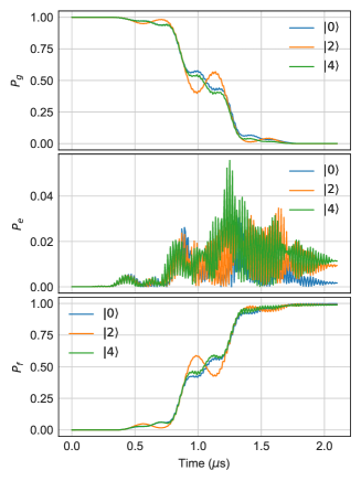
One way of satisfying all of these constraints is to adopt the approach shown in Fig. 2c of the main text. One strong drive is placed at a given detuning from (We choose ). This drive is shared among all photon-number selective transitions. The matching pair for each of these transitions is then given by a weaker tone at . In comparison with schemes where every Raman transition has a distinct pair of drive tones, this scheme is much simpler, and avoids the problem of accidentally driving unintended transitions with other tone pairings. The ancilla trajectory induced by the Raman SNAP operation is shown in Fig. S3. An important feature of the trajectory is that the population in shows a 10% dependence on the cavity photon number. This violates the condition of path-independence, and will therefore lead to propagation of ancilla errors due to decoherence-induced back-action. The reason for this non-ideal behavior is that the rotating wave approximation in Eq. S9 is only approximately justified due to the finite ratio of . This effect can be mitigated by moving to slower SNAP operation, at the cost of increased decoherence.
The unconditional swap that is applied before the final ancilla measurement requires a fast transition, and is therefore implemented with direct and drives (Fig. 2d in the main text).
S6 Error-transparency drive
In order to achieve error-transparency, we must modify the static interaction Hamiltonian
| (S30) |
so that . We do so by adding a drive at frequency , where is the ancilla transition frequency between and the third excited level , is the cavity resonance frequency, and is a detuning parameter. This drive addresses the sideband transition . In the appropriate rotating frame, the resulting Hamiltonian can be written as
| (S31) |
with the sideband driving rate. When , we can replace this with an approximate time-independent Hamiltonian
| (S32) | ||||
| (S33) |
Ignoring the terms involving , we can write the total effective interaction as
| (S34) |
For a given value of (if large enough), one can specify the corresponding value of such that , and therefore the net Hamiltonian becomes
| (S35) |
In practice, we choose . Increased decoherence induced by the drive and the appearance of unwanted transitions prevent us from using a stronger drive. As a consequence, hybridization of and will ensue, resulting in an approximate population mixing of . This is a second-order error, occurring only after ancilla relaxation takes place, and is included in the error analysis below (section S7).
S7 Error budget
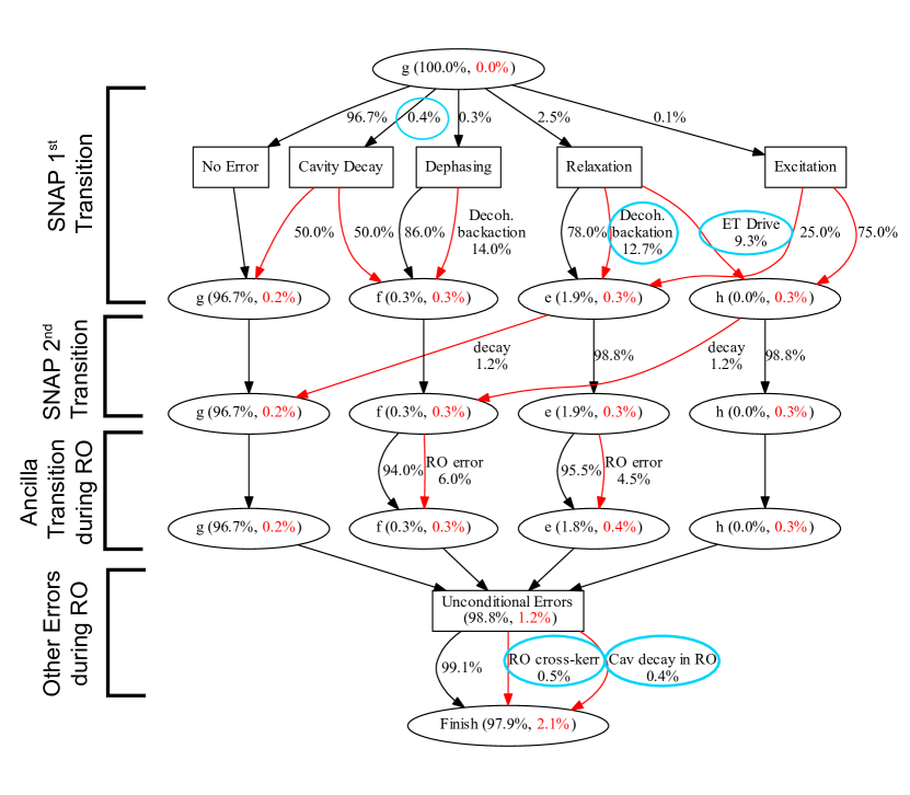
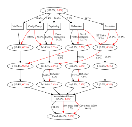
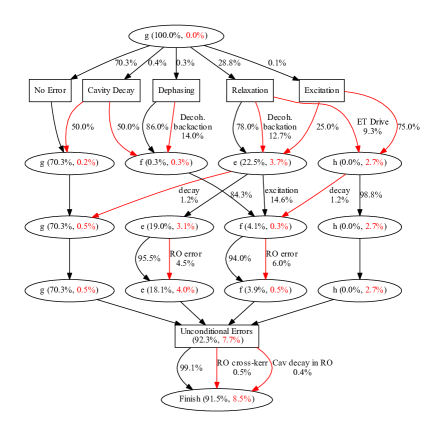
In order to understand which error mechanisms dominate the residual gate infidelity, we create an analytic model. Several types of errors are accounted for, including first and second-order ancilla transitions during the SNAP operation, transitions during the ancilla measurement, cavity transitions, and readout-induced cavity dephasing. The total predicted 2.1% error per operation is in good agreement with the measured value of 2.4%. In the diagram in Fig. S4, we can identify which error channels are dominant, and which are negligible. Second-order transitions, such as double decay from to , are of small enough probability to not contribute. Cavity decay, however, is quite significant, both during the SNAP operation (0.4%) and during the ancilla measurement (0.4%). In principle, this component can be addressed by introducing the cavity error correction as discussed at the end of section S2. Therefore, the dominant and concerning unaddressed error components are: readout-induced dephasing (cross-Kerr, 0.5%), decoherence-induced back-action (0.3%), ancilla relaxation during the ancilla measurement (especially from , 0.2%), and hybridization induced by the error-transparency drive, resulting in population of (0.3%).
| Parameter Name | Hamiltonian/Liouvillian Term | Quoted quantity | value |
|---|---|---|---|
| Transmon frequency | |||
| Cavity frequency | |||
| Readout frequency | |||
| Dispersive shift () | |||
| Dispersive shift () | |||
| Transmon anharmonicity | |||
| Cavity anharmonicity | |||
| Transmon relaxation | |||
| Transmon relaxation | |||
| Transmon dephasing | |||
| Transmon dephasing | |||
| Cavity relaxation | |||
| Transmon thermal population |
S8 Experimental setup
For a detailed description of the experimental setup, see Ref. Rosenblum et al. (2018). The measured values for the system parameters can be found in table SI.