∎
33institutetext: M.M. Korshunov 44institutetext: Kirensky Institute of Physics, Federal Research Center KSC SB RAS, Akademgorodok, 660036, Krasnoyarsk, Russia
44email: mkor@iph.krasn.ru
Effect of the additional Se layer on the electronic structure of iron-based superconductor FeSe/SrTiO3 ††thanks: This work was supported in part by “BASIS” Foundation for Development of Theoretical Physics and Mathematics.
Abstract
We use density functional theory to study the structure and the band structure of the monolayer FeSe deposited on the SrTiO3 substrate with the additional layer of Se between them. Top of the SrTiO3 is formed by the double TiO layer with and without oxygen vacancies. Several structures with different arrangements of the additional Se atoms above the double TiO layer is considered. Equilibrium structures were found and the band structures for them were obtained. Near the point of the Brillouin zone, the hole Fermi surface pockets persist and, additionally, an electron pocket appears. Thus neither the presence of the additional Se layer nor the oxygen vacancies in the double TiO layer leads to the sinking of hole bands below the Fermi level near the point. Necessity to include the strong electronic correlations into account is discussed.
Keywords:
Fe-based superconductors Monolayer FeSe SrTiO3 density functional theory1 Introduction
Iron-based materials represents a class of high- superconductors that is based on the conducting layer of Fe surrounded by As or Se in pnictides and chalcogenides, respectively y_kamihara_08 ; SadovskiiReview2008 ; IzyumovReview2008 ; IvanovskiiReview2008 ; JohnstonReview ; PaglioneReview ; LumsdenReview ; StewartReview ; Inosov2016 . Each of the constituents can be replaced by some other element thus providing a doping and/or crystal lattice distortion. This results in the rich phase diagram that includes, among others, antiferromagnetic and superconducting phases. Proximity of the magnetic phase implies the role of spin fluctuations in the formation of Cooper pairs HirschfeldKorshunov2011 . Stemming from the ideas of Berk and Schrieffer BerkSchrieffer , the theory of spin fluctuation-mediated pairing provides consistent explanation of several important features of superconductivity in Fe-based materials HirschfeldKorshunov2011 ; ChubukovReview2012 ; Korshunov2014eng . Observation of the spin resonance peak in inelastic neutron scattering KorshunovEreminResonance2008 ; Maier2008 ; Maier2009 ; KorshunovPRB2016 ; Korshunov2019 and the quasiparticle interference pattern Akbari2010 ; Wang2010 ; AkbariQPI2010 ; Hirschfeld2015 in scanning tunneling spectroscopy confirms sign-changing gap predicted by the spin fluctuation theory of superconductivity Mazin2008 ; Chubukov2008 ; Kuroki2008 ; Graser2009 ; MaitiKorshunovPRL2011 ; MaitiKorshunovPRB2011 ; MaitiKorshunov2012 ; Classen2017 . Other approaches to the theory includes pairing due to the orbital fluctuations supported by phonons Kontani or the Aslamasov-Larkin vertex corrections Onari2012 .
Discovery of superconductivity in FeSe monolayers with as high as 100 K presents another mystery in the physics of iron-based materials FeSeTc ; Zhang2015 ; GeFeSe100K ; ZhaoFeSeLiOHFeSe ; Sadovskii2016 . Different mechanisms of superconductive pairing in monolayer FeSe were suggested including specific realization of the electron-phonon interaction Lee2014 ; Coh2015 ; Gorkov2016 ; Kulic2017 , nematic fluctuations Kang2016 ; FernandesReview2017 ; Kang2018 , orbital fluctuations Yamakawa2017 , spin fluctuations Kreisel2017 , and spin fluctuations involving incipient bands Chen2015 . Recent advances in scanning tunneling spectroscopy of iron chalcogenides support sign-changing gap Du2017 ; Liu2019 ; Jandke2019 .
Any pairing theory is tightly connected to the underlaying band structure and the Fermi surface. Thus, knowledge of the band structure details becomes extremely important. Angle-resolved photoemission spectroscopy (ARPES) shows that there is only one kind of Fermi surface sheets – electron pockets around the corners of the Brillouin zone ( points), while there is no hole pockets around the center ( point) FeSeARPES . Moreover, with increasing number of FeSe layers hole pockets around the point become visible in ARPES and at the same time the superconductivity disappears TanFeSeARPES . Surprisingly, despite a successful qualitative and even semi-quantitative description of the bulk Fe-pnctides and Fe-chalcogenides electronic structure within the modern band structure calculation schemes, they fail to reproduce such a topology of the Fermi surface. For example, existing density functional studies do not reveal significant differences between the monolayer and double unit cell layer of FeSe LiuPRB2012 . There are at least two reasons why this may happen. First one is related to the global problem of the density functional theory (DFT) in describing the systems with strong electronic correlations (SEC). If this is the case, i.e. the monolayer FeSe represents a class of systems with SEC, then some specific approach is required to describe its electronic structure and, moreover, theory of superconductivity should be formulated taking SEC into account. There is, however, another possibility of why there is a disagreement between the results of DFT and the experimentally observed Fermi surface. It is related to the atomic structure of the FeSe/SrTiO3 interface. The interface seems to be more complicated then can be naively expected because the preparation of the monolayer FeSe is quite cumbersome. If FeSe deposited on graphene or SrTiO3 it doesn’t become neither metal nor superconductor. However, if it is deposited on Se-enriched SrTiO3 and then annealed, the superconductivity with high appears FeSeTc ; GeFeSe100K . The process of annealing and Se bombardment naturally modifies the surface layer of SrTiO3 . There are few experimental studies of the interface Li2DMat2016 ; Zou2016 , which revealed the presence of the TiO2 double layers on top of SrTiO3 . Both this and the possible oxygen vacancies due to the annealing were incorporated in the first principles calculations Bang2013 ; Xu2017 . They had some success in explaining the disappearance of the hole pocket around the point. Recent experimental study Zhao2018 utilized the high-angle annular dark-field scanning transmission electron microscopy (HAADF-STEM) images and revealed an additional Se layer located between FeSe monolayer and TiOx-terminated SrTiO3 . This new fact may be important for the FeSe band structure and have to be taken into account.
Here we use DFT calculations to study the influence of the additional Se layer on FeSe/(2TiO)SrTiO3 electronic structure. Several possible positions of additional Se atoms and of FeSe monolayer in the unit cell of heterostructure were modeled to search for favorable configurations and the electronic structure of these configurations were investigated.
The paper is organized as follows. Section 2 presents details of the computational procedure, Section 3 contains results and their discussion, and Section 4 is the conclusion.
2 Computational details
DFT p_hohenberg_64 ; wkohn65 calculations were carried out using Open source package for Material eXplorer software package (OpenMX, http://www.openmx-square.org) based on a linear combination of pseudoatomic orbital (PAO) method Ozaki2004 and norm-conserving pseudopotentials Bachelet1982 ; Kleinman1982 ; Blochl1990 ; Troullier1991 ; Morrison1993 . The cutoff energy value was equal to 150 Ry. The PAO basis set with for Fe and Ti, for Se and O, and for Sr were found to be sufficient to describe the structures. Cutoff radii of 10.0 a.u. for Sr, 7.0 a.u. for Ti and Se, 6.0 a.u. for Fe, and 5.0 a.u. for O were used. Exchange-correlation effects were taken into account in the generalized gradient approximation (GGA) by the Perdew-Burke-Ernzerhof (PBE) functional jperdew96 . The structures were relaxed until the forces acting on atoms and the translation vectors became less then Hartree/Borh. The convergence condition for the energy was Hartree. To simulate the two-dimensional (2D) structures using Periodic Boundary Conditions (PBC), the periodic replicas were separated by a vacuum spacing of at least 20 Åalong the axis. The first Brillouin zone (BZ) was sampled with -grid. Band structure calculations were performed along the high symmetry directions in BZ: . To avoid the edge effects on the atomic and electronic structures, the SrTiO3 supercell was used in calculations. The Visualization for Electronic and Structural Analysis (VESTA) software Momma2011 was used to visualize the atomic structures.
3 Results and discussion
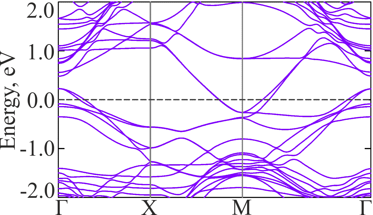
In Fig. 1, we show the band structure of the reference system, i.e. the FeSe/(2TiO)SrTiO3 heterostructure without vacancies and without the additional Se layer. Notice the bands slightly above the Fermi level () at the point, which have downward dispersion thus forming the hole Fermi surface pockets in the center of the BZ.
Oxygen vacancies play an important role, so we study the band structure of the FeSe/SrTiO3 system with and without O vacancies in the double TiO layer. To show the general effect of vacancies and to make the calculations manageable, we consider the case of one vacancy per two unit cells. This corresponds to 50% of vacancies and represents a limiting case, i.e. the result for the fractional number of vacancies would lie somewhere between the results for and . Thus, formally, we are dealing with the heterostructure. Since from the experimental study Zhao2018 the exact positions of Se atoms are not known, we considered several cases shown in Fig. 2. That is, Se is located above Ti atoms [Fig. 2(a),(b)], above lower [Fig. 2(c),(d)] and upper O [Fig. 2(e),(f),(g)] atoms of the double TiOx layer, and above the oxygen vacancy [Fig. 2(h)]. In the case of Se location below the lowest Se of FeSe monolayer, additional configurations was considered with shifted FeSe monolayer in the plane so that the additional Se atoms appears right below Fe atoms.
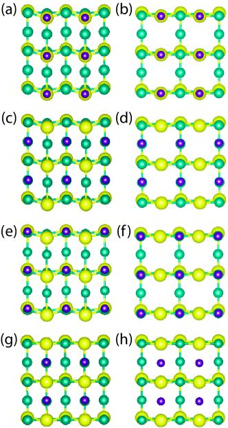
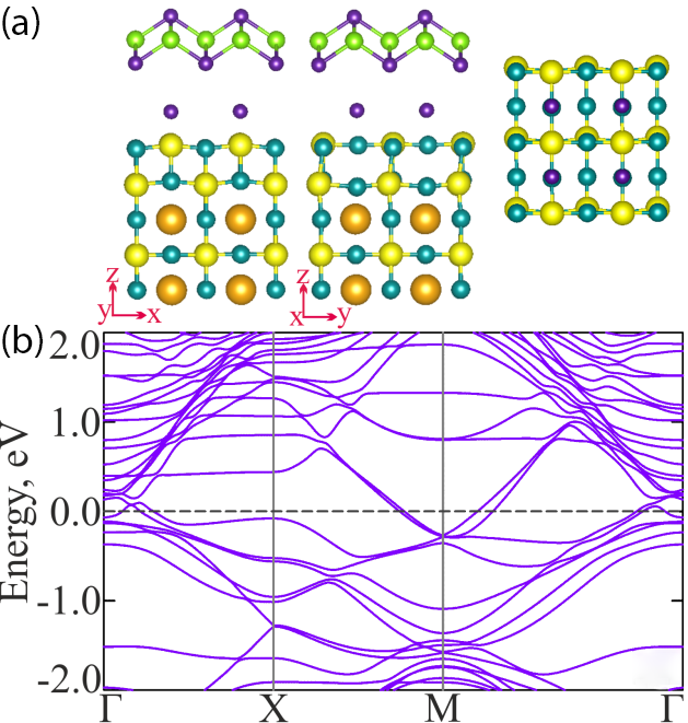
During the structure optimization, the additional Se atom moved to the position above the upper oxygen atoms of the double TiO layer, Fig. 2(g), or above the oxygen vacancies, Fig. 2(h). In both cases, location of the additional Se atom under the Fe atoms is energetically favorable. The resulting equilibrium configurations of heterostructure without and with oxygen vacancies are shown in Fig. 3(a) and (c), respectively. Corresponding band structures are shown in Fig. 3(b) and (d). In the structure without vacancies, the additional Se is above the surface of (2TiOx)SrTiO3 by and below the FeSe monolayer by . The charge transfer to the FeSe monolayer is electrons per FeSe formula unit (/FeSe). The resulting charge at the additional Se is positive ( /Se). As seen from the band structure in Fig. 3(b), the additional band crosses the Fermi level around the point. It results in the additional Fermi surface electron pocket in the center of the BZ. On the other hand, bands forming the hole pockets are still present and at the point they are at 0.23 eV above the . It is higher by 0.03 eV than in the reference system without additional Se layer, compare to Fig. 1.
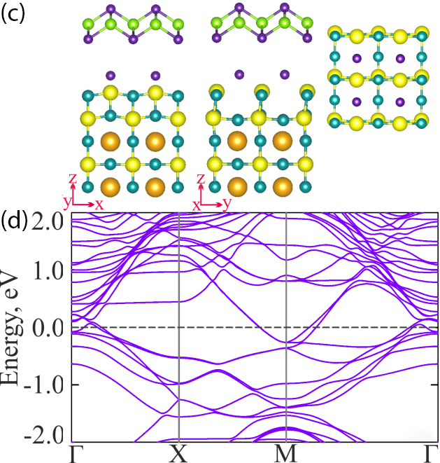
Presence of the oxygen vacancies [50% in the calculation, see Fig. 2(h)] in the upper layer of TiOx results in the shift of the additional Se towards the substrate layer by . Distance between the FeSe monolayer and the additional layer of Se becomes . Charge transfer to the FeSe monolayer is /FeSe. It is only by more than in the system without vacancies. The charge at the additional Se is /Se. Therefore, the most part of the charge is localized in the additional Se layer. The band structure, shown in Fig. 3(d), displays the presence of both hole and electron Fermi surface pockets around the point similar to the case without vacancies shown in panel (b).
From the study of the two energetically favorable cases, we see that the small increase of the electron charge in the FeSe monolayer due to the additional Se layer does not lead to the sinking of the hole bands below the Fermi level at the point. On the contrary, new electron pockets formed by the bands with upward dispersion below the Fermi level appear. In general, this is in a disagreement with the ARPES data FeSeARPES ; TanFeSeARPES . We see that including more details of the FeSe/SrTiO3 interface haven’t solved the mystery of the hole pocket absence in photoemission. In particular, both oxygen vacancies and additional Se layer certainly affect the band structure near the point, but this effect has nothing to do with the simple sinking of hole bands below the Fermi level. Therefore, we have to assume that some other mechanism affects the electronic structure. Natural choice is the effect of strong electronic correlations mentioned in the Introduction. Proper treatment of them requires a separate study. Some success in this direction was achieved within the LDA+DMFT (local density approximation+dynamical mean field theory) studies Nekrasov2017 ; Nekrasov2018
4 Conclusions
We have studied the effect of the additional Se layer on the band structure of the FeSe/SrTiO3 heterostructure. The additional layer is situated between the FeSe monolayer and the double TiOx layer on top of SrTiO3 . For and , the band structure near the point results in the hole Fermi surface pockets and, additionally, a new electron pocket. Therefore, the presence of the additional Se layer does not leads to the sinking of hole bands below the Fermi level. In the presence of the oxygen vacancies in the double TiO layer, Se atoms plays a role of the missing oxygen, i.e. it localizes the charge and prevents its transfer to the FeSe monolayer. We conclude that the strong electronic correlations have to be taken into account to peoperly describe the low energy physics of FeSe monolayers.
Acknowledgements.
The authors would like to thank Information Technology Center, Novosibirsk State University, Institute of Computational Modelling of SB RAS, Krasnoyarsk for providing the access to supercomputer facilities, and Irkutsk Supercomputer Center of SB RAS for providing the access to HPC-cluster “Akademik V.M. Matrosov” (Irkutsk Supercomputer Center of SB RAS, Irkutsk: ISDCT SB RAS; http://hpc.icc.ru, accessed 13.05.2019).References
- (1) Y. Kamihara, T. Watanabe, M. Hirano, H. Hosono, Journal of the American Chemical Society 130(11), 3296 (2008). DOI 10.1021/ja800073m. URL http://dx.doi.org/10.1021/ja800073m
- (2) M.V. Sadovskii, Phys. Usp. 51(12), 1201 (2008). DOI 10.1070/PU2008v051n12ABEH006820. URL https://ufn.ru/en/articles/2008/12/b/
- (3) Y.A. Izyumov, E.Z. Kurmaev, Phys. Usp. 51(12), 1261 (2008). DOI 10.1070/PU2008v051n12ABEH006733. URL https://ufn.ru/en/articles/2008/12/d/
- (4) A.L. Ivanovskii, Phys. Usp. 51(12), 1229 (2008). DOI 10.1070/PU2008v051n12ABEH006703. URL https://ufn.ru/en/articles/2008/12/c/
- (5) D.C. Johnston, Advances in Physics 59(6), 803 (2010). DOI 10.1080/00018732.2010.513480. URL http://dx.doi.org/10.1080/00018732.2010.513480
- (6) J. Paglione, R.L. Greene, Nat. Phys. 6(9), 645 (2010). URL http://dx.doi.org/10.1038/nphys1759
- (7) M.D. Lumsden, A.D. Christianson, Journal of Physics: Condensed Matter 22(20), 203203 (2010). URL http://stacks.iop.org/0953-8984/22/i=20/a=203203
- (8) G.R. Stewart, Rev. Mod. Phys. 83, 1589 (2011). DOI 10.1103/RevModPhys.83.1589. URL http://link.aps.org/doi/10.1103/RevModPhys.83.1589
- (9) D.S. Inosov, Comptes Rendus Physique 17(1-2), 60 (2016). DOI 10.1016/j.crhy.2015.03.001. URL http://www.sciencedirect.com/science/article/pii/S1631070515000523
- (10) P.J. Hirschfeld, M.M. Korshunov, I.I. Mazin, Reports on Progress in Physics 74(12), 124508 (2011). URL http://stacks.iop.org/0034-4885/74/i=12/a=124508
- (11) N.F. Berk, J.R. Schrieffer, Phys. Rev. Lett. 17, 433 (1966). DOI 10.1103/PhysRevLett.17.433. URL http://link.aps.org/doi/10.1103/PhysRevLett.17.433
- (12) A. Chubukov, Annual Review of Condensed Matter Physics 3(1), 57 (2012). DOI 10.1146/annurev-conmatphys-020911-125055. URL http://dx.doi.org/10.1146/annurev-conmatphys-020911-125055
- (13) M.M. Korshunov, Physics-Uspekhi 57(8), 813 (2014). DOI 10.3367/UFNe.0184.201408h.0882. URL http://stacks.iop.org/1063-7869/57/i=8/a=813
- (14) M.M. Korshunov, I. Eremin, Phys. Rev. B 78, 140509 (2008). DOI 10.1103/PhysRevB.78.140509. URL http://link.aps.org/doi/10.1103/PhysRevB.78.140509
- (15) T.A. Maier, D.J. Scalapino, Phys. Rev. B 78, 020514 (2008). DOI 10.1103/PhysRevB.78.020514. URL http://link.aps.org/doi/10.1103/PhysRevB.78.020514
- (16) T.A. Maier, S. Graser, D.J. Scalapino, P. Hirschfeld, Phys. Rev. B 79, 134520 (2009). DOI 10.1103/PhysRevB.79.134520. URL http://link.aps.org/doi/10.1103/PhysRevB.79.134520
- (17) M.M. Korshunov, V.A. Shestakov, Y.N. Togushova, Phys. Rev. B 94, 094517 (2016). DOI 10.1103/PhysRevB.94.094517. URL http://link.aps.org/doi/10.1103/PhysRevB.94.094517
- (18) M.M. Korshunov, Phys. Rev. B 98, 104510 (2018). DOI 10.1103/PhysRevB.98.104510. URL https://link.aps.org/doi/10.1103/PhysRevB.98.104510
- (19) A. Akbari, I. Eremin, P. Thalmeier, Phys. Rev. B 81, 014524 (2010). DOI 10.1103/PhysRevB.81.014524. URL https://link.aps.org/doi/10.1103/PhysRevB.81.014524
- (20) F. Wang, H. Zhai, D.H. Lee, Phys. Rev. B 81, 184512 (2010). DOI 10.1103/PhysRevB.81.184512. URL http://link.aps.org/doi/10.1103/PhysRevB.81.184512
- (21) A. Akbari, J. Knolle, I. Eremin, R. Moessner, Phys. Rev. B 82, 224506 (2010). DOI 10.1103/PhysRevB.82.224506. URL https://link.aps.org/doi/10.1103/PhysRevB.82.224506
- (22) P.J. Hirschfeld, D. Altenfeld, I. Eremin, I.I. Mazin, Phys. Rev. B 92, 184513 (2015). DOI 10.1103/PhysRevB.92.184513. URL https://link.aps.org/doi/10.1103/PhysRevB.92.184513
- (23) I.I. Mazin, D.J. Singh, M.D. Johannes, M.H. Du, Phys. Rev. Lett. 101, 057003 (2008). DOI 10.1103/PhysRevLett.101.057003. URL http://link.aps.org/doi/10.1103/PhysRevLett.101.057003
- (24) A.V. Chubukov, D.V. Efremov, I. Eremin, Phys. Rev. B 78, 134512 (2008). DOI 10.1103/PhysRevB.78.134512. URL http://link.aps.org/doi/10.1103/PhysRevB.78.134512
- (25) K. Kuroki, S. Onari, R. Arita, H. Usui, Y. Tanaka, H. Kontani, H. Aoki, Phys. Rev. Lett. 101, 087004 (2008). DOI 10.1103/PhysRevLett.101.087004. URL http://link.aps.org/doi/10.1103/PhysRevLett.101.087004
- (26) S. Graser, T. Maier, P. Hirschfeld, D. Scalapino, New Journal of Physics 11(2), 025016 (2009). URL http://stacks.iop.org/1367-2630/11/i=2/a=025016
- (27) S. Maiti, M.M. Korshunov, T.A. Maier, P.J. Hirschfeld, A.V. Chubukov, Phys. Rev. Lett. 107, 147002 (2011). DOI 10.1103/PhysRevLett.107.147002. URL http://link.aps.org/doi/10.1103/PhysRevLett.107.147002
- (28) S. Maiti, M.M. Korshunov, T.A. Maier, P.J. Hirschfeld, A.V. Chubukov, Phys. Rev. B 84, 224505 (2011). DOI 10.1103/PhysRevB.84.224505. URL http://link.aps.org/doi/10.1103/PhysRevB.84.224505
- (29) S. Maiti, M.M. Korshunov, A.V. Chubukov, Phys. Rev. B 85, 014511 (2012). DOI 10.1103/PhysRevB.85.014511. URL http://link.aps.org/doi/10.1103/PhysRevB.85.014511
- (30) L. Classen, R.Q. Xing, M. Khodas, A.V. Chubukov, Phys. Rev. Lett. 118, 037001 (2017). DOI 10.1103/PhysRevLett.118.037001. URL https://link.aps.org/doi/10.1103/PhysRevLett.118.037001
- (31) H. Kontani, S. Onari, Phys. Rev. Lett. 104, 157001 (2010). DOI 10.1103/PhysRevLett.104.157001. URL http://link.aps.org/doi/10.1103/PhysRevLett.104.157001
- (32) S. Onari, H. Kontani, Phys. Rev. Lett. 109, 137001 (2012). DOI 10.1103/PhysRevLett.109.137001. URL https://link.aps.org/doi/10.1103/PhysRevLett.109.137001
- (33) W. Qing-Yan, L. Zhi, Z. Wen-Hao, Z. Zuo-Cheng, Z. Jin-Song, L. Wei, D. Hao, O. Yun-Bo, D. Peng, C. Kai, W. Jing, S. Can-Li, H. Ke, J. Jin-Feng, J. Shuai-Hua, W. Ya-Yu, W. Li-Li, C. Xi, M. Xu-Cun, X. Qi-Kun, Chinese Physics Letters 29(3), 037402 (2012). URL http://stacks.iop.org/0256-307X/29/i=3/a=037402
- (34) Z. Zhang, Y.H. Wang, Q. Song, C. Liu, R. Peng, K. Moler, D. Feng, Y. Wang, Science Bulletin 60(14), 1301 (2015). DOI https://doi.org/10.1007/s11434-015-0842-8. URL http://www.sciencedirect.com/science/article/pii/S2095927316303711
- (35) J.F. Ge, Z.L. Liu, C. Liu, C.L. Gao, D. Qian, Q.K. Xue, Y. Liu, J.F. Jia, Nat Mater 14(3), 285 (2015). URL http://dx.doi.org/10.1038/nmat4153
- (36) L. Zhao, A. Liang, D. Yuan, Y. Hu, D. Liu, J. Huang, S. He, B. Shen, Y. Xu, X. Liu, L. Yu, G. Liu, H. Zhou, Y. Huang, X. Dong, F. Zhou, K. Liu, Z. Lu, Z. Zhao, C. Chen, Z. Xu, X.J. Zhou, Nat Commun 7, 1 (2016). URL http://dx.doi.org/10.1038/ncomms10608
- (37) M.V. Sadovskii, Phys. Usp. 59(10), 947 (2016). DOI 10.3367/UFNe.2016.06.037825. URL https://ufn.ru/en/articles/2016/10/b/
- (38) J.J. Lee, F.T. Schmitt, R.G. Moore, S. Johnston, Y.T. Cui, W. Li, M. Yi, Z.K. Liu, M. Hashimoto, Y. Zhang, D.H. Lu, T.P. Devereaux, D.H. Lee, Z.X. Shen, Nature 515, 245 (2014). DOI 10.1038/nature13894. URL https://doi.org/10.1038/nature13894
- (39) S. Coh, M.L. Cohen, S.G. Louie, New Journal of Physics 17(7), 073027 (2015). DOI 10.1088/1367-2630/17/7/073027. URL https://doi.org/10.1088/1367-2630/17/7/073027
- (40) L.P. Gor’kov, Phys. Rev. B 93, 060507 (2016). DOI 10.1103/PhysRevB.93.060507. URL https://link.aps.org/doi/10.1103/PhysRevB.93.060507
- (41) M.L. Kulić, O.V. Dolgov, New Journal of Physics 19(1), 013020 (2017). DOI 10.1088/1367-2630/19/1/013020. URL https://doi.org/10.1088/1367-2630/19/1/013020
- (42) J. Kang, R.M. Fernandes, Phys. Rev. Lett. 117, 217003 (2016). DOI 10.1103/PhysRevLett.117.217003. URL https://link.aps.org/doi/10.1103/PhysRevLett.117.217003
- (43) R.M. Fernandes, A.V. Chubukov, Reports on Progress in Physics 80(1), 014503 (2017). URL http://stacks.iop.org/0034-4885/80/i=1/a=014503
- (44) J. Kang, R.M. Fernandes, A. Chubukov, Phys. Rev. Lett. 120, 267001 (2018). DOI 10.1103/PhysRevLett.120.267001. URL https://link.aps.org/doi/10.1103/PhysRevLett.120.267001
- (45) Y. Yamakawa, H. Kontani, Phys. Rev. B 96, 045130 (2017). DOI 10.1103/PhysRevB.96.045130. URL https://link.aps.org/doi/10.1103/PhysRevB.96.045130
- (46) A. Kreisel, B.M. Andersen, P.O. Sprau, A. Kostin, J.C.S. Davis, P.J. Hirschfeld, Phys. Rev. B 95, 174504 (2017). DOI 10.1103/PhysRevB.95.174504. URL https://link.aps.org/doi/10.1103/PhysRevB.95.174504
- (47) X. Chen, S. Maiti, A. Linscheid, P.J. Hirschfeld, Phys. Rev. B 92, 224514 (2015). DOI 10.1103/PhysRevB.92.224514. URL https://link.aps.org/doi/10.1103/PhysRevB.92.224514
- (48) Z. Du, X. Yang, D. Altenfeld, Q. Gu, H. Yang, I. Eremin, P. Hirschfeld, I.I. Mazin, H. Lin, X. Zhu, H.H. Wen, Nature Physics 14, 134 (2017). DOI 10.1038/nphys4299. URL https://doi.org/10.1038/nphys4299
- (49) C. Liu, Z. Wang, Y. Gao, X. Liu, Y. Liu, Q.H. Wang, J. Wang, Phys. Rev. Lett. 123, 036801 (2019). DOI 10.1103/PhysRevLett.123.036801. URL https://link.aps.org/doi/10.1103/PhysRevLett.123.036801
- (50) J. Jandke, F. Yang, P. Hlobil, T. Engelhardt, D. Rau, K. Zakeri, C. Gao, J. Schmalian, W. Wulfhekel, Phys. Rev. B 100, 020503 (2019). DOI 10.1103/PhysRevB.100.020503. URL https://link.aps.org/doi/10.1103/PhysRevB.100.020503
- (51) D. Liu, W. Zhang, D. Mou, J. He, Y.B. Ou, Q.Y. Wang, Z. Li, L. Wang, L. Zhao, S. He, Y. Peng, X. Liu, C. Chen, L. Yu, G. Liu, X. Dong, J. Zhang, C. Chen, Z. Xu, J. Hu, X. Chen, X. Ma, Q. Xue, X.J. Zhou, Nat. Commun. 3, 931 (2012). URL http://dx.doi.org/10.1038/ncomms1946
- (52) S. Tan, Y. Zhang, M. Xia, Z. Ye, F. Chen, X. Xie, R. Peng, D. Xu, Q. Fan, H. Xu, J. Jiang, T. Zhang, X. Lai, T. Xiang, J. Hu, B. Xie, D. Feng, Nat Mater 12(7), 634 (2013). URL http://dx.doi.org/10.1038/nmat3654
- (53) K. Liu, Z.Y. Lu, T. Xiang, Phys. Rev. B 85, 235123 (2012). DOI 10.1103/PhysRevB.85.235123. URL https://link.aps.org/doi/10.1103/PhysRevB.85.235123
- (54) F. Li, Q. Zhang, C. Tang, C. Liu, J. Shi, C. Nie, G. Zhou, Z. Li, W. Zhang, C.L. Song, K. He, S. Ji, S. Zhang, L. Gu, L. Wang, X.C. Ma, Q.K. Xue, 2D Materials 3(2), 024002 (2016). DOI 10.1088/2053-1583/3/2/024002. URL https://doi.org/10.1088/2053-1583/3/2/024002
- (55) K. Zou, S. Mandal, S.D. Albright, R. Peng, Y. Pu, D. Kumah, C. Lau, G.H. Simon, O.E. Dagdeviren, X. He, I. Bozović, U.D. Schwarz, E.I. Altman, D. Feng, F.J. Walker, S. Ismail-Beigi, C.H. Ahn, Phys. Rev. B 93, 180506 (2016). DOI 10.1103/PhysRevB.93.180506. URL https://link.aps.org/doi/10.1103/PhysRevB.93.180506
- (56) J. Bang, Z. Li, Y.Y. Sun, A. Samanta, Y.Y. Zhang, W. Zhang, L. Wang, X. Chen, X. Ma, Q.K. Xue, S.B. Zhang, Phys. Rev. B 87, 220503 (2013). DOI 10.1103/PhysRevB.87.220503. URL https://link.aps.org/doi/10.1103/PhysRevB.87.220503
- (57) M. Xu, X. Song, H. Wang, Phys. Chem. Chem. Phys. 19, 7964 (2017). DOI 10.1039/C7CP00173H. URL http://dx.doi.org/10.1039/C7CP00173H
- (58) W. Zhao, M. Li, C.Z. Chang, J. Jiang, L. Wu, C. Liu, J.S. Moodera, Y. Zhu, M.H.W. Chan, Science Advances 4(3) (2018). DOI 10.1126/sciadv.aao2682. URL https://advances.sciencemag.org/content/4/3/eaao2682
- (59) P. Hohenberg, W. Kohn, Phys. Rev. 136(3B), B864 (1964). DOI 10.1103/PhysRev.136.B864
- (60) W. Kohn, L.J. Sham, Phys. Rev. 140, 1133 (1965). DOI 10.1103/PhysRev.140.A1133
- (61) T. Ozaki, H. Kino, Phys. Rev. B 69, 195113 (2004). DOI 10.1103/PhysRevB.69.195113. URL https://link.aps.org/doi/10.1103/PhysRevB.69.195113
- (62) G.B. Bachelet, D.R. Hamann, M. Schlüter, Phys. Rev. B 26, 4199 (1982). DOI 10.1103/PhysRevB.26.4199. URL https://link.aps.org/doi/10.1103/PhysRevB.26.4199
- (63) L. Kleinman, D.M. Bylander, Phys. Rev. Lett. 48, 1425 (1982). DOI 10.1103/PhysRevLett.48.1425. URL https://link.aps.org/doi/10.1103/PhysRevLett.48.1425
- (64) P.E. Blöchl, Phys. Rev. B 41, 5414 (1990). DOI 10.1103/PhysRevB.41.5414. URL https://link.aps.org/doi/10.1103/PhysRevB.41.5414
- (65) N. Troullier, J.L. Martins, Phys. Rev. B 43, 1993 (1991). DOI 10.1103/PhysRevB.43.1993. URL https://link.aps.org/doi/10.1103/PhysRevB.43.1993
- (66) I. Morrison, D.M. Bylander, L. Kleinman, Phys. Rev. B 47, 6728 (1993). DOI 10.1103/PhysRevB.47.6728. URL https://link.aps.org/doi/10.1103/PhysRevB.47.6728
- (67) J.P. Perdew, K. Burke, M. Ernzerhof, Phys. Rev. Lett. 77, 3865 (1996). DOI 10.1103/PhysRevLett.77.3865
- (68) K. Momma, F. Izumi, Journal of Applied Crystallography 44(6), 1272 (2011). DOI 10.1107/S0021889811038970. URL https://doi.org/10.1107/S0021889811038970
- (69) I.A. Nekrasov, N.S. Pavlov, M.V. Sadovskii, JETP Letters 105(6), 370 (2017). DOI 10.1134/S0021364017060029. URL https://doi.org/10.1134/S0021364017060029
- (70) I.A. Nekrasov, N.S. Pavlov, M.V. Sadovskii, Journal of Experimental and Theoretical Physics 126(4), 485 (2018). DOI 10.1134/S1063776118040106. URL https://doi.org/10.1134/S1063776118040106