figure \cftpagenumbersofftable
The X-ray Polarization Probe mission concept
Co-authors: Ivan Agudo (CSIC),
Lorella Angelini (GSFC),
Matteo Bachetti (INAF),
Luca Baldini (U. Pisa),
Matthew G. Baring (Rice U.),
Wayne Baumgartner (MSFC),
Ronaldo Bellazzini (INFN),
Stefano Bianchi (U. Roma Tre),
Niccolò Bucciantini (INAF/OAC),
Ilaria Caiazzo (UBC),
Fiamma Capitanio (INAF/IAPS),
Paolo Coppi (Yale U.),
Enrico Costa (INAF/IAPS),
Ettore Del Monte (INAF),
Alessandra De Rosa (IAPS/INAF),
Jason Dexter (MPE),
Laura Di Gesu (ASI),
Niccolo’ Di Lalla (INFN),
Victor Doroshenko (U. Tübingen),
Michal Dovciak (Cz. Acad. Sci.),
Riccardo Ferrazzoli (INAF/IAPS),
Felix Fürst (ESAC),
Alan Garner (MIT),
Pranab Ghosh (Tata Inst.),
Denis González-Caniulef (UBC),
Victoria Grinberg (U. Tübingen),
Shuichi Gunji (Yamagata U.),
Dieter Hartmann (Clemson U.),
Kiyoshi Hayashida (Osaka),
Jeremy Heyl (UBC),
Joanne Hill (GSFC),
Adam Ingram (Oxford U.),
Wataru Buz Iwakiri (Chuo U.),
Svetlana Jorstad (BU),
Phil Kaaret (U. Iowa),
Timothy Kallman (GSFC),
Vladimir Karas (Cz. Acad. Sci.),
Ildar Khabibullin (MPA),
Takao Kitaguchi (RIKEN),
Jeff Kolodziejczak (MSFC),
Chryssa Kouveliotou (GWU),
Ioannis Liodakis (Stanford U.),
Thomas Maccarone (Texas Tech U.),
Alberto Manfreda (INFN),
Frederic Marin (U. Strasbourg),
Andrea Marinucci (ASI),
Craig Markwardt (GSFC),
Alan Marscher (BU),
Giorgio Matt (U. Roma Tre),
Mark McConnell (UNH),
Jon Miller (U. Michigan),
Ikuyuki Mitsubishi (Nagoya U.),
Tsunefumi Mizuno (U. Hiroshima),
Alexander Mushtukov (Leiden U.),
C.-Y. Ng (Hong Kong U.),
Michael Nowak (Washington U.),
Steve O’Dell (MSFC),
Alessandro Papitto (INAF/OAR),
Dheeraj Pasham (MIT),
Mark Pearce (KTH),
Lawrence Peirson (Stanford U.),
Matteo Perri (SSDC/ASI),
Melissa Pesce-Rollins (INFN),
Vahe Petrosian (Stanford U.),
Pierre-Olivier Petrucci (U. Grenoble),
Maura Pilia (INAF/OAC),
Andrea Possenti (INAF/OAC, U. Cagliari),
Juri Poutanen (U. Turku),
Chanda Prescod-Weinstein (UNH),
Simonetta Puccetti (ASI),
Tuomo Salmi (U. Turku),
Kevin Shi (MIT),
Paolo Soffitta (IAPS/INAF),
Gloria Spandre (INFN),
James F. Steiner (SAO),
Tod Strohmayer (GSFC),
Valery Suleimanov (U. Tübingen),
Jiri Svoboda (Cz. Acad. Sci.),
Jean Swank (GSFC),
Toru Tamagawa (RIKEN),
Hiromitsu Takahashi (Hiroshima U.),
Roberto Taverna (U. Roma Tre),
John Tomsick (UCB),
Alessio Trois (INAF/OAC),
Sergey Tsygankov (U. Turku),
Roberto Turolla (U. Padova),
Jacco Vink (U. Amsterdam),
Jörn Wilms (U. Erlangen-Nuremberg),
Kinwah Wu (MSSL, UCL),
Fei Xie (INAF),
George Younes (GWU),
Alessandra Zaino (U. Roma Tre),
Anna Zajczyk (GSFC, UMBC),
Silvia Zane (MSSL, UCL),
Andrzej Zdziarski (NCAC),
Haocheng Zhang (Purdue U.),
Wenda Zhang (Cz. Acad. Sci.),
Ping Zhou (U. Amsterdam)
Abstract: The X-ray Polarization Probe (XPP) is a second generation X-ray polarimeter following up on the Imaging X-ray Polarimetry Explorer (IXPE). The XPP will offer true broadband polarimetery over the wide 0.2-60 keV bandpass in addition to imaging polarimetry from 2-8 keV. The extended energy bandpass and improvements in sensitivity will enable the simultaneous measurement of the polarization of several emission components. These measurements will give qualitatively new information about how compact objects work, and will probe fundamental physics, i.e. strong-field quantum electrodynamics and strong gravity.
1 Key Science Goals and Objectives
The X-ray Polarization Probe (XPP) is a mission concept for a second-generation polarimetry mission following up on the Imaging X-ray Polarimetry Explorer (IXPE) mission to be launched in 2021 [1, 2]. IXPE will open the field of observational X-ray polarimetry with a modest instrument, compatible with the constraints of NASA’s Small Explorer program, and consequently has a modest bandpass (a factor of 4 between the limiting energies at the upper and lower ends of the band) and effective area (peaking near 130 cm2 at 2.2 keV). XPP, as a second generation instrument, aspires to at least an order of magnitude increase in both effective area and band width and to substantially improved imaging capabilities. XPP will extend the 2-8 keV bandpass of IXPE to 0.2 keV - 60 keV and improve on IXPE’s sensitivity in IXPE’s core energy range from 2-8 keV by a factor between 3 and 10. The XPP includes two telescopes with Hitomi style mirrors simultaneously illuminating three instruments which span the 0.2 - 60 keV band and one telescope with IXPE-type imaging polarimetric capabilities (15” Half Power Diameter, HPD) in the 2-8 keV energy range. The use of novel Si mirrors may make it possible to improve the angular resolution of all three telescopes to a few arc sec.
These capabilities will make it possible to obtain quantitatively new information about the most extreme objects in the Universe: black holes, neutron stars, magnetars and Active Galactic Nuclei. Although the number of objects accessible to XPP is still modest (a few hundred sources with high signal to noise ratio polarization measurements), the observations will enable physics-type experiments probing the inner workings of these sources of high-energy X-rays, and probing the underlying physical laws in truly extreme conditions. Our XPP science white paper[3] identified three high-profile science investigations: (1) Dissect the structure of inner accretion flow onto black holes and observe strong gravity effects; (2) Use neutron stars as fundamental physics laboratories; (3) Probe how cosmic particle accelerators work and what role magnetic fields play.
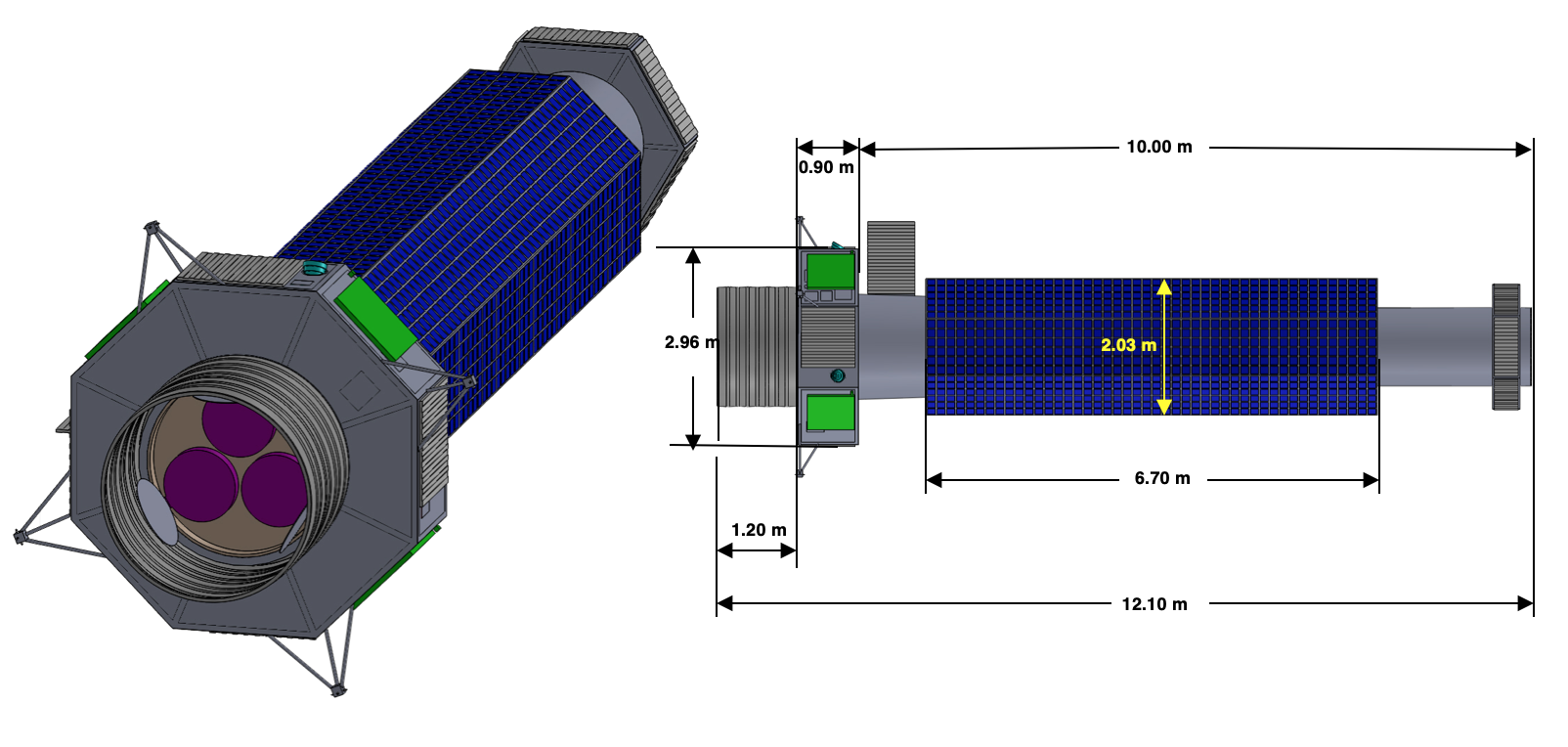
Here we report on a possible implementation of the XPP based on a detailed mission implementation study performed in cooperation with the COMPASS Team at the NASA Glenn Research Center. The XPP science objectives require sensitivity to faint signals, which drives requirements for large collecting area over a wide band and precise control of systematic effects. The large area requires grazing incidence mirrors. The need to limit systematics leads to tight requirements on alignment and pointing, which XPP addresses with a stiff and thermally stable optical bench. The optical bench is designed without the need for in-orbit extension as shown in Figure 1. To reduce residual and uncalibrated asymmetries in the payload, XPP will rotate about the line of sight.
 |
2 Technical Overview
2.1 Key Observables
The XPP measures the arrival times, energies, and linear polarization of 0.2-60 keV X-rays making use of three complimentary techniques. The instruments exploit polarization dependent scattering cross sections at low energies (below 1 keV), measure the polarization dependent initial direction of the photoelectron that is ejected after a photoelectric absorption at intermediate 2-10 keV photon energies, and measure the polarization dependent direction of a Compton scattered photon at 10-60 keV photon energies. The cross over in energy between photoelectric dominated interactions and Compton dominated interactions depends on the atomic number of the absorbing medium; for the XPP instrument complement, the photoelectric process dominates the sensitivity below 10 keV and the Compton process dominates above. Separate photon counting instruments observe simultaneously below 1 keV (scattering), below 10 keV (photoelectric), and above 10 keV (Compton).
2.2 Instrument and Spacecraft Performance Requirements
The XPP measures the arrival times and energies of 0.2-60 keV X-rays with s and % energy resolution at all wavelengths, respectively. Most importantly, it measures the linear polarization fraction and polarization angle. The design aims at a sensitivity of 1% Minimum Detectable Polarization (MDP) at 99% confidence level for a 105 sec observation of a 1 mCrab source. This sensitivity will enable the study of statistical samples (each: 10-50 sources) of the key sources: stellar mass black holes, active galactic nuclei, pulsars, magnetars, X-ray binaries, super nova remnants, and blazars. Systematic errors below 0.2% in the polarization fraction are required to measure the typical polarization fractions of 5% with sufficient accuracy to distinguish between competing models. Imaging polarimetry with angular resolutions between 1” (goal) and 15” (requirement) enable the studies of extended sources such as pulsar wind nebulae, supernova remnants, and the jets from active galactic nuclei.
 |
Three of the instruments on XPP do not have an imaging capability, which creates two high level Attitude Control requirements. First, pointing must be controlled to a small fraction of the telescope point spread function and second, the Observatory must rotate about the line of sight to both measure and eliminate residual asymmetries in the angular response.
2.3 Mission Architecture
The XPP payload consists of three grazing incidence X-ray mirrors and four focal instruments. Each mirror has a diameter of 60 cm and a focal length of 10 m.
Two of the telescopes are designed for maximum throughput, and simultaneously illuminate a Low Energy Polarimeter (LEP, sensitive from 0.2-0.8 keV), a Medium Energy Polarimeter (MEP, sensitive from 2 - 10 keV), and a High Energy Polarimeter (HEP, sensitive from 6 - 60 keV). These instruments are not imaging, but provide broad band spectral coverage of unconfused point sources. Most compact object X-ray sources are unconfused and provide excellent opportunities to study matter under extreme conditions.
The third telescope is optimized for imaging, and has a replicated nickel mirror illuminating an imaging polarimeter. Both the mirror and detector are larger versions of the instruments being developed for IXPE, and provide imaging polarimetry in the 2-8 keV band. Imaging confirms that point sources are unconfused, and opens the possibility of studying extended sources such as supernova remnants and jets.
For a launch in the late 2020s, it is likely possible to replace all three mirrors with the multi-layer coated crystalline Silicon optics[4] being developed for Lynx and other potential X-ray observatories. The Si optics are expected to have similar mass and effective area as the Hitomi-style mirrors and much better angular resolution (near 1”) than the IXPE mirrors.
The Observatory is put into a deep (7000 x 114000 km), 48 hour orbit which provides over 40 hours of uninterrupted observations of most of the sky (targets within of the sun and anti-sun are unavailable). Data downlink and most other spacecraft functions are performed near perigee.
 |
2.4 Payload Components
2.4.1 Spectro-polarimetry telescopes
The COMPASS design study assumed that two of the mirrors are optimized for throughput and employ the design recently employed for Hitomi[5] but with multi-layer coatings to increase effective area above 10 keV. Each mirror is 60 cm in diameter and has a 10 m focal length.
The foil mirrors are expected to have a Half Power Diameter of arcmin and the multi-layer reflectors provide about 1700 cm2 below 10 keV and over 100 cm2 at all energies above 50 keV.
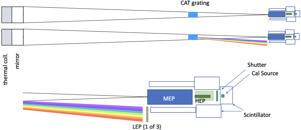
Each of these mirrors simultaneously illuminates a Low Energy Polarimeter (LEP), Medium Energy Polarimeter (MEP), and High Energy Polarimeter (HEP) as shown schematically in Figure 2. The LEP consists of gratings which select energy, variable spacing multilayer mirrors which are tuned to the Bragg angle where they are efficient polarizers and imaging detectors which map detector position to photon energy; the concept is described by Marshall et al.[6]. The gratings are transparent above 2 keV, and their support structure obscures 10% of the beam, while scattering low energy photons to gratings/detectors outside the focal plane. The MEP is a photoelectric polarimeter with a Time Projection Chamber readout[7] based on the detector developed for PRAXyS[8]. The MEP is designed to have both an entrance and an exit window, so that higher energy photons can pass through the MEP and illuminate the HEP. The HEP is a scattering polarimeter based on the PolSTAR instrument[9] (designed for space operation) and the X-Calibur[10] balloon payload instrument. The HEP is surrounded with scintillation detectors to provide an anti-coincidence based background reduction. A detailed instrument design will be necessary in order to package all three instruments and the associated electronics. A novel feature of these telescopes is that all three instruments operate simultaneously; there is no need for a mechanism to move each instrument separately and sequentially into the focal plane.
 |
2.4.2 Imaging polarimetry telescope
The third mirror has similar diameter and focal length and provides higher angular resolution; the replicated nickel process for the IXPE mirrors is described by Ramsey[11]. This mirror illuminates an imaging photoelectric pixel polarimeter[12] similar to the detector planned for the IXPE[1]. This mirror achieves an HPD of 15”, and enables polarimetric imaging at sub arc minute scales.
2.5 Focal Plane Instruments
Unlike the instruments in the pioneering sounding rocket [13] and satellite [14] experiments, which required rotation about the line of sight to develop the polarization signature, the XPP polarimeters are each capable of measuring polarization without rotation. This allows Observatory rotation to be employed to reduce and remove any systematic effects which arise from azimuthal asymmetries in the mirrors or instruments.
2.5.1 Low Energy Polarimeter
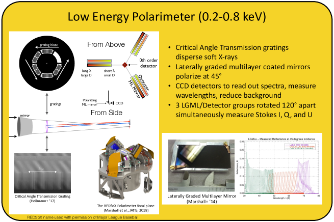
The Low Energy Polarimeter (LEP) exploits the polarization dependence of Bragg scattering. Simultaneous measurements are performed at three angles. The LEP is made of three well-studied components. Transmission gratings separate the incident radiation by wavelength dispersing onto custom laterally graded multilayer coated mirrors (LGMLs) that serve as polarization sensitive analyzers, reflecting only one linear polarization onto imaging detectors. The LGMLs are aligned and mounted such that each dispersed photon strikes the mirrors at an angle that satisfies the Bragg condition for reflection at about 45∘. At this angle, the polarization in the plane of reflection is highly suppressed, yielding modulation factors over 90%. The detector coordinates give the photon wavelength, as in other dispersive spectrometers. With CCDs as readout detectors, the spectral resolution assists in background reduction as the dispersion determines the energy of interest. More conceptual detail is provided in Marshall et al. (2018)[6]. Using LGMLs at three distinct orientations (e.g., 120∘ to each other) provides enough information to measure the I, Q, and U Stokes parameters from which the linear polarization angle and magnitude can be determined.
Gratings closer to the mirror provide greater dispersion (and thus potentially more precision in the energy determination), at the cost of requiring larger grating area and larger detectors. Critical angle transmission gratings designed for ARCUS[15] with 200 nm periods and LGMLs with period variations of 0.88 Å/mm[16] have been tested in the lab and are sufficient for this project. For the current design, we assume that the gratings are 3 m above the focal plane; a 0.2 keV photon is dispersed 93 mm while a 0.7 keV photon is dispersed 26.5 mm. As the optical bench is fixed rather than extensible, this distance could be modified without affecting the conceptual design.
 |
2.5.2 Medium Energy Polarimeter
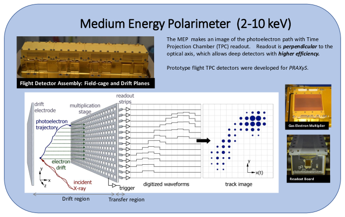
The Medium Energy Polarimeter (MEP) exploits the polarization dependence of the photoelectric effect by measuring the initial direction of the photoelectron which is correlated with the photon electric field. Detectors are based on the successful PRAXyS design [7], although we assume that the same sensitivity can be achieved with a detector that has twice the pressure and half the depth (e.g. total quantum efficiency is conserved). The individual tracks will be half as long. Maintaining the same effective resolution along the track requires readout electrodes with a pitch of half that used for GEMS/PRAXyS. Polarization sensitivity has been measured from 2 - 8 keV[17] with modulation factors ranging from 20% to 55%. Improvements in track reconstruction algorithms continue to improve the sensitivity[18]. The PRAXyS concept also needs to be modified with a rear window so that high energy photons can exit the detector and interact in the Compton scattering experiment.
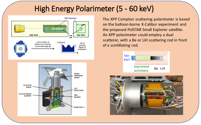
2.5.3 High Energy Polarimeter
The High Energy Polarimeter (HEP) exploits the angular dependence of the Compton scattering cross section which peaks 90∘ away from the electric field vector. The active element consists of a cylinder of scattering material (with Lithium and Beryllium sections) surrounded by imaging detectors, similar to the X-Calibur and PolSTAR detectors [9, 10]. A modulation factor of over the full energy range of the HEP is achieved. The recent 2018/2019 balloon flight of the X-Calibur mission resulted in the first constraints on the linear polarization of the 15-35 keV X-rays from the accreting strongly magnetized neutron star GX 3012 and validated the detection principle and the technical implementation. The addition of a segmented scintillator rear scatterer would enable imaging polarimetry with 1 arcmin angular resolution.
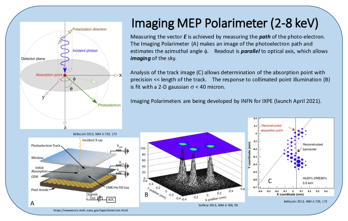 |
2.5.4 Imaging Polarimeters
The Imaging Polarimeter is a Gas Pixel Detector (GPD)[19], developed in Italy and refined significantly over the past 20 years. As with the MEP, the goal is to measure the initial direction of the photoelectron for 2-8 keV X-rays. In the case of the GPD, however, the ionization track drifts toward a Gas Electron Multiplier to generate more electrons for high signal/noise and is then read out using an anode array with 50 m hexagonal pixels. IXPE will have three such detectors at the focal planes of three independent optics, so these detectors will have a high technical readiness level after fabrication and calibration this year and launch in 2021. For IXPE, the anodes are directly connected to CMOS-based Application Specific Integrated Circuits (ASICs) with pixels with individual analog electronics[20]. A schematic of the IXPE GPD is shown in Figure 6. The GPD spatial resolution is about 120 m, so that the detector can be paired with optics capable of 2-5” imaging, up to a factor of 10 improvement over IXPE. The IXPE detectors are 1 cm deep, filled with a mixture of dimethyl ether and He at an 4:1 partial pressure ratio, sealed at one atmosphere, and have shown no changes in performance greater than 1% per year. Modulation factors of 20% (2 keV) to 65% (8 keV) have been measured in the lab[21]. The bandpass of GPD (and TPC) polarimeters can be shifted and extended to higher energies (e.g. 6-35 keV) with suitable choices of the gas mixture and pressure (e.g. [22]). Using a single imaging polarimeter sensitive at higher energies, or replacing one of the scattering polarimeters with a high-energy GPDM might be interesting options that should be evaluated with suitable trade off studies.
2.6 Mission and Spacecraft components
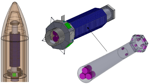
2.6.1 Orbit and Launch Vehicle
A medium class launch vehicle (e.g. Atlas 511) can place XPP directly into a 7000 x 114,000 km orbit. This orbit has a 48 hour period, long life, and provides conditions favorable for observations for over 40 hours per orbit. Lunar perturbations are important on long time scales; apogee, perigee, and inclination vary on year time scales for the orbit studied here, with evolution similar to the Chandra orbit. Figure 7 shows the Observatory inside the Atlas 5m fairing. Only the sunshade and the thermal pre-collimators in front of the mirrors require deployment after launch. The entire observatory rotates about the telescopes’ line of sight with a period of 1 hour.
 |
2.6.2 Attitude Control
The attitude control control system consists of currently and commercially available components including a Northrup Grumman internally redundant SIRU gyroscope, six coarse sun sensors, three SODERN SED36 star trackers (2 operational and a cold spare), six Honeywell HR-14 reaction wheels, reaction wheel isolators, an aspect camera coaligned with the telescope, and cold gas thrusters. The star trackers provide 1 arcsec, 3 end of life (3 year) performance; the reaction wheels can store up to 50 Nms of angular momentum and slew the spacecraft through 90 deg in 30 minutes. Momentum unloading is performed with the cold gas thrusters approximately every 2 days, preferentially during the 8 hours surrounding perigee which are unsuited to observation.
2.6.3 Propulsion
Propulsion is required only to null out tip-off rates and for momentum management; the launch vehicle is capable of delivering XPP to the final orbit. 60 kg of cold gas is estimated to provide enough capability to manage momentum for over 20 years. Redundancy is provided by storing the gas in four tanks, each of which serves an independent Reaction Control System pod with 4 thrusters. The pods are distributed uniformly in azimuth around the spacecraft.
2.6.4 Mechanical
The XPP primary structure combines instrument and spacecraft functions. The telescope metering structure consists of a conical tube constructed from aluminum honeycomb and composite facesheets. Mirrors are mounted within the larger end of the telescope tube; detectors are mounted within the smaller end. Spacecraft components are largely mounted outside the mirror end of the tube while instrument electronics and thermal control systems are mounted outside the detector end of the tube. The outside of the tube is surrounded by fixed solar panels; four phased array antenna panels surround the satellite bus. As the antennas and solar panels are fixed, neither system is a source of disturbance torques to the pointing and control systems. The rigid structure is continuously heated to remove the possibility of thermal distortions related to the slow rotation.
2.6.5 Power and thermal control
The fixed solar cell arrays provide sufficient power to operate in all orientations excluding 30 degree (half angle) cones about the sun and anti-sun directions. Solar cell efficiency of 29% and a three year degradation of 13% are assumed. Additional degradation (e.g. as might be expected for operations beyond 3 years) can be accommodated by increasing the size of solar keep out zones, or mission planning that ensures the battery charge will be high during potential solar occultations at perigee.
2.6.6 Communications and Tracking
XPP has four fixed phased array X-band antennas, decoupling the downlink schedule from observations. A single DSN downlink with an 11 m dish per day can downlink 100 Gb per day. S band communications are used for commanding and some housekeeping.
3 Technical Resources and Margins
The XPP dry mass is estimated to be 2152 kg. Allowing for 60 kg of cold gas propellant, and 40% growth, a launch mass of 2904 kg was assumed for launch services calculations. A 9% margin to the Atlas 511 capability remains, even after derating the Atlas capability by 10% and accounting for the mass of the adapter.
The solar arrays are designed to accommodate the highest power mode (Science plus communication) at the worst case solar angle (30 degrees between line of sight and the sun) after allowing for a 30% growth in power demand. Additional ’margin’ can be created by reducing the field of regard. XPP is not limited by considerations of mass or power.
Cold gas propellant is the only consumable on XPP. For the current design, the propellant has an estimated lifetime of 20 years.
4 Technology Drivers
The XPP payload is based on instruments and components which substantial design and test heritage. The spacecraft design presented here uses components and approaches available today.
5 Organizations, Partnerships, and Current Status
The XPP study was performed by representatives from MIT, GSFC and Washington University with input from IXPE members at the MSFC. These individuals and institutions have been building and qualifying versions of the LEP, MEP, HEP, and IXPE for a number of years and expect to work collaboratively to propose the XPP when the opportunity arises. We expect substantial international contributions from Italian and Japanese co-investigators with regards to the mirror, the polarimeters, the analysis, and scientific participation and leadership.
6 Cost and Schedule
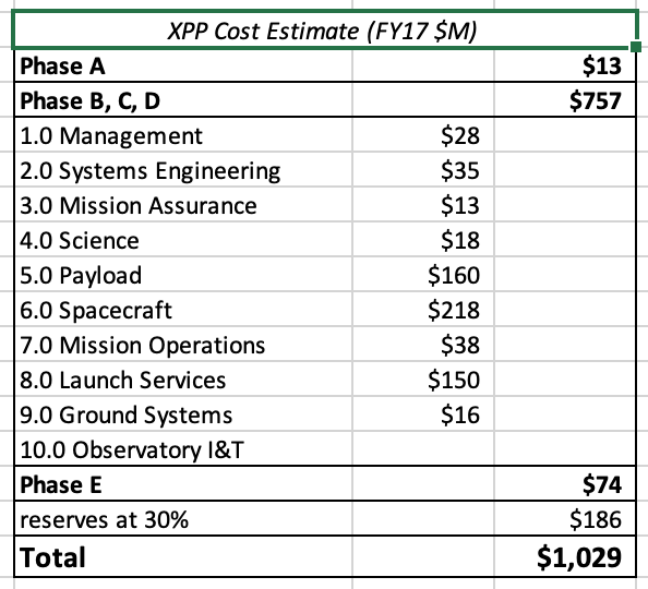 |
A mission cost estimate was developed as part of a Concept study performed at the Glenn Research Center COMPASS design center in September 2017. The Life Cycle Cost includes 3 years of operations. The XPP investigators self-assessment that the payload technologies are at TRL 6 is based on the on-going development for flight of the IXPE detectors, the flight design and independent TRL 6 qualification of the GEMS/PRAXyS detectors, the successful development of the X-Calibur balloon detectors, and the advanced development of all key components of the LEP.
Payload costs (WBS 5) were estimated using PRICE True Planning and payload component masses estimated by the investigators.
Spacecraft costs (WBS 6) are based on the assumption that the spacecraft is provided by an industry partner responsible for all components (no GFE) and a 10% fee is included.
Because payload components are distributed throughout the Observatory, Integration and Test costs were estimated for the combined Payload and Spacecraft system. 30% of these costs are included in the spacecraft costs (WBS 6) with the balance accounted for in the traditional NASA WBS 10 (Observatory I&T) element.
The total Phase E costs were estimated from the Mission Operations Cost Estimating Tool (MOCET) and include (parametrically) the downlink costs ( $5M for a 3 year mission) and some Science Operations in addition to the costs traditionally carried in WBS 7.
The Launch costs (WBS 8) were taken to be $150M, which was the guidance being given to Probe Class studies being performed in the GSFC Mission Design Lab at the time the XPP study was performed. Reserves are not carried against this cost.
A risk analysis based on a Monte Carlo analysis which incorporated the relative uncertainties of each element of the costs produced a point estimate which was equal to the mean of all the runs. All costs are presented in constant FY17 dollars.
The cost estimate is summarized by NASA standard top level WBS elements in Figure 8.
7 Summary
X-ray polarimetry is now becoming an observational area of astrophysics. A second-generation instrument like XPP will vastly increase the number of observable sources and will be able to probe even small polarization fractions. Imaging polarimetry and broad-band spectro-polarimetry will provide qualitatively new insights into the structure of a broad range of astrophysical objects and have the power to revolutionize our understanding of many of the most energetic phenomena in the Universe.
Acknowledgements.
We gratefully acknowledge the COMPASS Mission Design Team at the NASA Glenn Research Center: Steve Oleson, Tony Colozza, James Fincannon, James Fittje, John Gyekenyesi, Robert Jones, Nicholas Lantz, Mike Martini, John Mudry, J. Michael Newman, Tom Packard, Dave Smith, Sarah Tipler, and Elizabeth Turnbull.References
-
[1]
M. C. Weisskopf, B. Ramsey, S. O
’Dell, et al., “The imaging x-ray polarimeter experiment (ixpe),” Proc. SPIE 9905 (2016). - [2] S. O’Dell et al., “The imaging x-ray polarimetry explorer (ixpe): technical overview,” Proc. SPIE 10699 (2018).
- [3] H. S. Krawczynski et al., “Astro2020 science white paper: Using x-ray polarimetry to probe the physics of black holes and neutron stars,” (2019). [arXiv:1904.09313v1].
- [4] W. W. Zhang, K. D. Allgood, M. P. Biskach, et al., “Astronomical x-ray optics using mono-crystalline silicon: high resolution, light weight, and low cost,” in Proc. SPIE, Society of Photo-Optical Instrumentation Engineers (SPIE) Conference Series 10699, 106990O (2018).
- [5] T. Okajima, Y. Soong, P. Serlemitsos, et al., “First peek of ASTRO-H Soft X-ray Telescope (SXT) in-orbit performance,” in Proc. SPIE, Society of Photo-Optical Instrumentation Engineers (SPIE) Conference Series 9905, 99050Z (2016).
- [6] H. L. Marshall, H. M. Günther, R. K. Heilmann, et al., “Design of a broadband soft x-ray polarimeter,” Journal of Astronomical Telescopes, Instruments, and Systems 4, 011005 (2018).
- [7] J. E. Hill, J. K. Black, K. Jahoda, et al., “The x-ray polarimeter instrument on board the polarimeter for relativistic astrophysical x-ray sources (praxys) mission,” Proc. SPIE 9905 (2016).
- [8] K. Jahoda, T. R. Kallman, C. Kouveliotou, et al., “The polarimeter for relativistic astrophysical x-ray sources,” Proc. SPIE 9905 (2016).
- [9] H. S. Krawczynski, D. Stern, F. A. Harrison, et al., “X-ray polarimetry with the polarization spectroscopic telescope array (polstar),” Astroparticle Physics 75, 8–28 (2016).
- [10] F. Kislat et al., “Optimization of the design of x-calibur for a long-duration balloon flight and results from a one-day test flight,” Journal of Astronomical Telescopes, Instruments, and Systems 4(1), 1 – 9 – 9 (2018).
- [11] B. D. Ramsey, “Optics for the imaging x-ray polarimetry explorer,” 10399 (2017).
- [12] F. Muleri, P. Soffitta, L. Baldini, et al., “Performance of the gas pixel detector: an x-ray imaging polarimeter for upcoming missions of astrophysics,” Proc SPIE 9905 (2016).
- [13] R. Novick, M. C. Weisskopf, R. Berthelsdorf, et al., “Detection of X-Ray Polarization of the Crab Nebula,” ApJL 174, L1 (1972).
- [14] M. C. Weisskopf, E. H. Silver, H. L. Kestenbaum, et al., “A precision measurement of the X-ray polarization of the Crab Nebula without pulsar contamination.,” ApJL 220, L117–L121 (1978).
- [15] R. K. Heilmann, A. R. Bruccoleri, and M. L. Schattenburg, “High-efficiency blazed transmission gratings for high-resolution soft x-ray spectroscopy,” in Proc. SPIE, Society of Photo-Optical Instrumentation Engineers (SPIE) Conference Series 9603, 960314 (2015).
- [16] H. L. Marshall, N. S. Schulz, D. L. Windt, et al., “The use of laterally graded multilayer mirrors for soft x-ray polarimetry,” in Proc SPIE, 9603, 960319 (2015).
- [17] W. B. Iwakiri, J. K. Black, R. Cole, et al., “Performance of the PRAXyS X-ray polarimeter,” Nuclear Instruments and Methods in Physics Research A 838, 89–95 (2016).
- [18] T. Kitaguchi, K. Black, T. Enoto, et al., “An optimized photoelectron track reconstruction method for photoelectric X-ray polarimeters,” Nuclear Instruments and Methods in Physics Research A 880, 188–193 (2018).
- [19] E. Costa, P. Soffitta, R. Bellazzini, et al., “An efficient photoelectric X-ray polarimeter for the study of black holes and neutron stars,” Nature 411, 662–665 (2001).
- [20] R. Bellazzini, G. Spandre, M. Minuti, et al., “Direct reading of charge multipliers with a self-triggering CMOS analog chip with 105 k pixels at 50 m pitch,” Nuclear Instruments and Methods in Physics Research A 566, 552–562 (2006).
- [21] F. Muleri, P. Soffitta, L. Baldini, et al., “Spectral and polarimetric characterization of the Gas Pixel Detector filled with dimethyl ether,” Nuclear Instruments and Methods in Physics Research A 620, 285–293 (2010).
- [22] G. Tagliaferri, A. Hornstrup, J. Huovelin, et al., “The NHXM observatory,” Experimental Astronomy 34, 463–488 (2012).