Bound states in the continuum in symmetric and asymmetric photonic crystal slabs
Abstract
We develop a semi-analytical model to describe bound states in the continuum (BICs) in photonic crystal slabs. We model leaky modes supported by photonic crystal slabs as a transverse Fabry-Perot resonance composed of a few propagative Bloch waves bouncing back and forth vertically inside the slab. This multimode Fabry-Perot model accurately predicts the existence of BICs and their positions in the parameter space. We show that, regardless of the slab thickness, BICs cannot exist below a cut-off frequency, which is related to the existence of the second-order Bloch wave in the photonic crystal. Thanks to the semi-analyticity of the model, we investigate the dynamics of BICs with the slab thickness in symmetric and asymmetric photonic crystal slabs. We evidence that the symmetry-protected BICs that exist in symmetric structures at the -point of the dispersion diagram can still exist when the horizontal mirror symmetry is broken, but only for particular values of the slab thickness.
pacs:
42.25.Fx,42.70.Qs,02.70.-cI Introduction
Photonic crystals (PhCs) consist of a periodic modulation of the refractive index at the wavelength scale Joannopoulos, J. D. and Johnson, S. G. and Winn and D. (2008); Sakoda (2005) and PhC slabs are formed by etching a one- or two-dimensional (1D or 2D) PhC in a dielectric layer acting as an optical waveguide. Compared to three-dimensional (3D) PhCs, the simplified architecture of PhC slabs makes them attractive for on-chip integrated photonics Notomi (2010); Kuramochi (2016). In addition, their peculiar diffraction properties have enabled a wide variety of applications, including filtersBaets et al. (2001); Mateus et al. (2004); Ding and Magnusson (2004), vertical-cavity surface-emitting lasers (VCSEL)Sciancalepore et al. (2013), thermal emissionInoue et al. (2014), and structural color generation Brongersma et al. (2014); Shen et al. (2015).
It was recently pointed out that PhC slabs can support optical bound states in the continuum (BICs) Hsu et al. (2013); Blanchard et al. (2014); Hsu et al. (2016). A BIC (also called embedded eigenvalue Monticone and Alù (2014)) is a bound state that exists at the same energy level as a continuum of radiation modes Von Neuman and Wigner (1929); Friedrich and Wintgen (1985). In PhC slabs, it corresponds to an eigenmode that is truly guided (no radiative leakage) despite the fact that it lies above the light cone in the dispersion diagram , with the angular frequency and the wavevector. The absence of leakage originates from two different physical mechanisms: a symmetry incompatibility or a destructive interference between different leakage channels Hsu et al. (2013).
From a strictly theoretical point of view, BICs, and especially the ones resulting from an interference mechanism, are definitely counter-intuitive and intriguing modes. From a practical point of view, however, BICs do not really exist. Indeed, in a real non-ideal structure, they are anyway faintly coupled to the radiation continuum because of technological imperfections, roughness, or finite size of the device. A BIC thereby becomes a leaky mode with extremely low leakage, i.e., with a very large quality factor, . Therefore, if a PhC slab can be fabricated with geometrical parameters close enough to the ideal ones, it exhibits a very sharp resonance with an extremely high quality factor whose value is only limited by technological constraints. Such high- resonances that result from the existence of a BIC nearby in the parameter space have been recently investigated Yoon et al. (2015); Blanchard et al. (2016); Sadrieva et al. (2017) and exploited for lasing Kodigala et al. (2017); Ha et al. (2018) and sensing applications Liu et al. (2017); Romano et al. (2018); Yesilkoy et al. (2019).
Up to now, the existence of BICs and their location in the parameter space has been calculated either with rigorous numerical methods Azzam et al. (2018); Bulgakov et al. (2018); Li and Yin (2016); Wang et al. (2016a), coupled-wave theory Wang et al. (2016b); Yang et al. (2014); Ni et al. (2016), or a perturbation approachBlanchard et al. (2014); Yuan and Lu (2017). Some interesting proposals of numerical approaches especially suitable for such problems have been put forwardGao et al. (2016); Bulgakov and Maksimov (2018). Fully numerical approaches are cumbersome even for simple geometries since the whole parameter space has to be explored blindly to find a BIC. Using a perturbation approach is an interesting alternative. However, if the coupled-wave formalism is accurate for PhC slabs with a low refractive-index contrast, the accuracy drops as the contrast increases. Iterative schemes have been proposed to improve the accuracy of the coupled-wave formalism for high refractive-index contrasts but at the cost of a drastic loss in simplicity Wang et al. (2016b).
To ease the practical implementation of PhC slabs supporting BICs, one needs approximate models that yield fast yet accurate predictions of the BIC location in the parameter space. Improving the understanding of the physical mechanisms that lead to the BIC formation is also an important issue. We propose a semi-analytical model that does not rely on a perturbative approach. The model presents several advantages. First, it explicitly contains the interference mechanism that leads to the formation of a BIC. Secondly, it yields quantitative predictions of the corresponding optogeometric parameters for any refractive index contrast.
BICs in PhC slabs are leaky modes whose radiative leakage vanishes for a particular set of optogeometric parameters. Their modeling is intrinsically linked to the phenomenon of guided-mode resonance, which corresponds to the resonant excitation of a leaky mode. Over the years, guided-mode resonance has been described by several theoretical formalisms, such as, for instance, coupled-wave theory Fan et al. (2003), perturbation methods Fehrembach and Sentenac (2003), or polology framework Popov et al. (1986); Fehrembach et al. (2002). Of a particular interest for the purposes of this work is an approach proposed in 2006 that consists of modeling the reflection and transmission of a PhC slab as a transverse Fabry-Perot resonance composed of several waves bouncing back and forth inside the slab Lalanne et al. (2006). This multimode Fabry-Perot model has been used with waves to study the optical properties of high contrast gratings (HCGs) Lalanne et al. (2006); Karagodsky et al. (2010, 2011); Karagodsky and Chang-Hasnain (2012). In this article, we extend the model to waves and apply it to the calculation of the dispersion curve and the quality factor of leaky modes supported by 1D PhC slabs. We show that the model is able to quantitatively predict the appearance of BICs and their position in the parameter space.
Let us emphasize that the multimode Fabry-Perot model is particularly well-suited for the study of BICs. First, the waves used in the model to build the transverse resonance are exactly the waves that destructively interfere to form a BIC. They have thus a clear physical meaning and are not virtual intermediary means for the calculation, even in the case of structures far from the perturbation regime. Secondly, these waves are bouncing back and forth vertically inside the PhC slab. The slab thickness is thus a crucial parameter to understand the formation of BICs by destructive interference. The model predictions are analytical with respect to this geometrical parameter. Thirdly, these waves possess cut-off frequencies below which they cannot propagate. Since the multimode Fabry-Perot model explicitly contains these cut-off frequencies, the zones in the space where BICs of different composition, judging by the number of constituent waves, can (or cannot) exist become apparent.
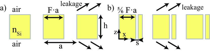
We apply the multimode Fabry-Perot model to 1D PhC slabs that are either symmetric or asymmetric with respect to a vertical axis (-axis in this work), see Fig. 1 The existence of BICs in asymmetric structures is scarcely documented in the literature Wang et al. (2016a); Koshelev et al. (2018). The model by its nature does not discriminate between symmetric or asymmetric slabs; the physical interpretation and the computational cost remains the same as symmetry is broken. Thus, we still benefit from the semi-analytical character of the model and we can quickly explore the parameter space. We evidence the existence of BICs in 1D PhC slabs with a horizontal asymmetry and we study their evolution as the asymmetry parameter is tuned continuously.
We first calculate and describe in Section II the different types of BICs that can exist in a symmetric 1D PhC slab, see Fig. 1(a), to set the foundations for further discussion. These different BICs have already been discussed separately in the literature, but here we show that all of them can exist together in a given geometry. In Section III, we present the multimode Fabry-Perot model and we show that it can accurately predict the existence of all types of BICs. We also discuss some limitations of the model. We finally apply the model in Section IV to an asymmetric 1D PhC slab, see Fig. 1(b). Section V concludes the work.
II Symmetric one-dimensional photonic crystal slabs
We consider here a symmetric lamellar 1D PhC slab, that is a periodic array of slits in a dielectric membrane with refractive index embedded in air, as shown in Fig. 1(a). The PhC period, the membrane thickness, and the filling factor in dielectric material are respectively denoted with , , and . We study the leaky modes supported by this structure in Transverse Electric (TE) polarization, i.e., with an electric field polarized along the slits in the direction.
The modes of the PhC slab are characterized by a wavevector and an eigenfrequency . Because of radiative leakage – for modes with a real wavevector located above the light cone – the eigenfrequencies are complex with a non-zero imaginary part. The latter is related to the mode quality factor, . Numerical calculations in this work are performed with the rigorous coupled-wave analysis (RCWA) Moharam et al. (1995). The modes are calculated by searching for the poles of the scattering matrix in the complex frequency plane Bai et al. (2013); Lalanne et al. (2019). The number of Fourier harmonics retained in the expansion of the electromagnetic field is with .
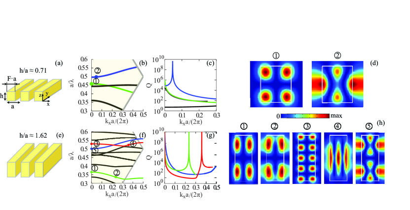
Figure 2 shows the different types of BICs that can exist in a symmetric 1D PhC slab. It also evidences the crucial role of the slab thickness in the formation mechanism of BICs. Figure 2(b) displays the dispersion curves of the first four leaky modes with the lowest frequency for and . The normalized frequency of the modes has been calculated as a function of the normalized -component of the wavevector , which is varied inside the first Brillouin zone, for a fixed (non-conical mount). The quality factors of the four modes are shown in Fig. 2(c). Two modes (green and blue curves) exhibit a BIC along their dispersion curve while the other two (black curves) do not. Indeed, the quality factor of the green mode diverges for and that of the blue mode diverges for . The locations of these two BICs in the dispersion diagram are shown with dots labeled (1) and (2) in Fig. 2(b). The corresponding electric fields are displayed in Fig. 2(d).
The existence of the BIC labeled (1) at (the -point) can be easily understood: radiative leakage is prohibited due to symmetry incompatibility. The field profile of the mode is antisymmetric with respect to , , and cannot couple to the symmetric profile of a plane wave with . This kind of BICs had been identified in earlier works on PhC slabs; in recent literature they are sometimes referred to as symmetry-protected BICs Hsu et al. (2013, 2016).
The existence of the second BIC labeled (2) is, however, more intriguing. Since its field presents no particular symmetry, it should, in principle, be coupled to the radiation continuum. However, radiative leakage is exactly suppressed at . This “accidental” disappearance of leakage results from destructive interference between several leakage channels Hsu et al. (2013). In the literature this type of BIC can be referred to as a resonance-trapped Kodigala et al. (2017); Hsu et al. (2016), or a Friedrich-Wintgen BIC Friedrich and Wintgen (1985).
As the thickness of the PhC slab increases to (same filling factor ), more modes appear in the spectral range of interest and the number of BICs increases as well, see Figs. 2(e)-(h). Our calculations show five BICs whose locations in the dispersion diagram of Fig. 2(f) are marked with the dots labeled from (1) to (5); the corresponding electric fields are shown in Fig. 2(h). Figure 2(g) displays the quality factors of the three modes that exhibit one or two BICs along their dispersion curve. The green mode has a diverging quality factor at , a symmetry-protected BIC [antisymmetric field profile (1)], and another one at due to destructive interference [field profile (2) with no particular symmetry]. Similarly, the red mode has the same kinds of BICs at [antisymmetric field profile (3)] and [field profile (4)]. Finally, the blue mode at exhibits a BIC despite its symmetric field profile (5) thanks to a destructive interference mechanism. Using the model described in Section III, the difference between BICs (2) and (4) will become apparent: the former can be described by a Fabry-Perot model with waves, while the latter requires waves.
As summarized in Table 1, we can distinguish two different types of BICs in a symmetric 1D PhC slab. First, leakage can be forbidden because of symmetry incompatibility between the mode of the PhC slab and the plane waves of the radiation continuum. Such symmetry-protected BICs can only exist at ; they have an antisymmetric field profile. Their existence does not depend on the geometrical parameters of the PhC slab, provided that the horizontal symmetry is conserved. Secondly, leakage can also be suppressed by destructive interference mechanisms. This can happen equally at (with a symmetric field profile) and at . In the latter case, the field profile presents no strict symmetry, but it can be sorted in two categories: the field is either quasi-symmetric [e.g., BIC (4) in Fig. 1(h)] or quasi-antisymmetric [e.g., BIC (2) in Fig. 1(h)]. By the prefix quasi, we mean that the BIC belongs to the dispersion curve of a leaky mode that is either symmetric or antisymmetric at . In contrast to the first type of BIC, the existence of such BICs formed by destructive interference strongly depends on the geometrical parameters of the PhC slab. It is thus not straightforward to predict their precise position along the dispersion curve.
| Symmetry incompatibility | Destructive interference | |||
|---|---|---|---|---|
| antisymmetric BIC | symmetric BIC | |||
| no BIC |
|
If previous works have qualitatively explained the destructive interference mechanism that leads to the formation of a BIC, see for instance Ref. Hsu et al., 2013, to our knowledge, none has made the argument quantitative. In the following Section, we present a multimode Fabry-Perot model that allows for a simple yet quantitative analysis of the interference mechanism between the different Bloch waves composing a leaky mode. Thanks to its semi-analytical character, the model allows for easy calculations of the BIC positions in the dispersion diagram and their variation as a function of the slab thickness.
III Multimode Fabry-Perot model
We derive a semi-analytical model that predicts the dispersion curve and the quality factor of leaky modes supported by a PhC slab. We extend an approach proposed in Ref. Lalanne et al., 2006 for the calculation of the reflection and transmission of a PhC slab. A leaky mode is nothing but a transverse Fabry-Perot resonance composed of several Bloch waves (BWs) bouncing back and forth vertically inside the slab. This description is perfectly rigorous as long as a sufficiently large number of waves is taken into account. This is the mathematical ground of RCWA, also known as the Fourier modal method Moharam et al. (1995). In the case of subwavelength periodic structures, only a small number of BWs are propagative, the other ones being evanescent Lalanne et al. (1999, 2006). Neglecting the impact of the evanescent waves provides approximate results that can be very accurate, provided that the slab thickness is large enough, typically larger than the decay length of the least attenuated evanescent wave Lalanne et al. (2006).
In the following, we first introduce some notations and write the general equations that lead to an exact calculation of the leaky modes dispersion. We then neglect the evanescent BWs and derive closed-form expressions for the dispersion curve and the quality factor with , , and propagative waves. We evidence that BICs can only exist when at least two Bloch waves are propagative. We finally validate the model by comparing its semi-analytical predictions to the exact calculations shown in Fig. 2.
III.1 Notations and general equations
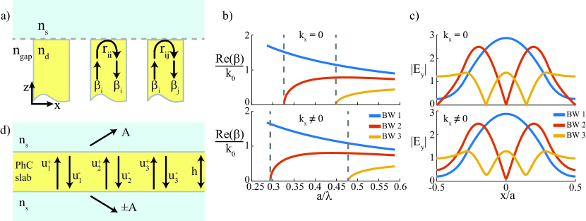
Before building a multimode Fabry-Perot resonance in a PhC slab of thickness , we need to solve the problem of a single interface between a semi-infinite PhC and a semi-infinite homogeneous medium, see Fig. 3(a). We denote by the propagation constant of the BW along the vertical direction. In a non-absorbing PhC, is either purely real (propagative wave) or purely imaginary (evanescent wave). The number of propagative BWs depends on the geometry. For example, for , , and in the band , only up to three BWs are propagative in a symmetric lamellar 1D PhC slab. Their propagation constants are shown in Fig. 3(b), where we can observe the second and third BW cut-offs at and , respectively. Note that the fundamental BW (largest propagation constant, blue curve) has no cut-off and is propagative whatever the ratio. The corresponding field profiles are shown in Fig. 3(c). The fundamental BW is symmetric and the higher-order BWs have alternately an antisymmetric or a symmetric field profile. For , the cut-off frequencies vary with and the BWs are no longer strictly symmetric nor antisymmetric.
As the BW is incident on an interface with a homogeneous medium, it is reflected with a reflection coefficient . In addition, it is reflected into a different BW with a cross-reflection coefficient , and transmitted as a propagative plane wave with a transmission coefficient . The coefficients , , and are the generalized Fresnel coefficients for an interface between a homogeneous and a periodic media. Note that we limit ourselves to the case where a single plane wave is propagative in the homogeneous medium – the zeroth diffraction order of the PhC slab. The energy contained in this plane wave corresponds to the radiative leakage.
In a PhC slab of thickness , the BWs are reflected at the top and bottom interfaces. Thus, they propagate back and forth inside the slab as illustrated in Fig. 3(d). We denote by and the amplitudes of the up- and down-propagating wave, respectively. The phase origin for the amplitude (resp. ) is taken at the bottom interface (resp. the top interface).
Leaky modes of a PhC slab are solutions of Maxwell’s equations in the absence of an incident wave. If one considers a finite number of BWs (propagative and evanescent BWs), the amplitudes and are related by
| (1) |
The number of BWs is equal to the truncation rank of the Fourier series in RCWA Moharam et al. (1995), in Fig. 2. For the sake of simplicity, we consider a PhC slab surrounded by the same homogeneous medium above and below. The equations can be straightforwardly generalized to the case of two different media (PhC slab lying over a substrate, see Supplemental Material for more details); two different families of reflection coefficients and have to be considered Lecamp et al. (2005).
Equations (1) can be rewritten in a matrix form
| (2) |
where the vector is built with the amplitudes and , , and the matrix contains all reflections and cross-reflection coefficients. A leaky mode is a non-trivial solution of this linear system of equations; it corresponds to a pair (with a real number and a complex number) that satisfies
| (3) |
with being the determinant of a matrix. We calculate rigorously with RCWA the parameters of a single interface (, , , ), and thus the matrix , as a function of the wavelength for a fixed value of the wave vector . Then, Eq. (3) can be solved, typically with an iterative procedure such as the generic Newton method or a different method using a Padé approximation Bai et al. (2013), to find the complex wavelength of the leaky mode. The dispersion curve and the quality factor are then given respectively by and .
Regarding the radiative leakage, the amplitude of the outgoing propagative plane wave is given by
| (4) |
The radiative leakage results from the interference of the BWs amplitudes being transmitted by the interface. Therefore, the leaky mode of the PhC slab is a BIC if, and only if, the interference is perfectly destructive. One readily realizes the crucial role of the slab thickness in this mechanism since it drives the value of the phase difference between the different BWs.
Solving Eq. (3) for a large number of BWs, hence containing a bunch of evanescent waves, yields a rigorous and exact result for the dispersion curve and quality factor. On the other hand, since the period of the PhC slab is subwavelength, neglecting all the evanescent BWs to keep only a small number of propagative BWs drastically reduces the size of the linear system in Eq. (1). Within this approximation, it is possible to derive closed-form expressions for the dispersion curve, the quality factor , and the radiative leakage , as shown hereafter. In particular, these expressions provide analytical results with respect to the thickness .
III.2 Transverse resonance for wave
Let us start with the simplest case when a single BW is propagative inside the PhC slab, all the other waves being evanescent. Although self-evident, this case allows us to introduce the main equations of the model. The single-mode regime occurs when the period-to-wavelength ratio is small, typically between the limit (quasi-static limit) and the cut-off of the second BW. For the example in Fig. 3(b), it corresponds to across all from zero to the light line.
For (a single propagative BW), Eq. (3) simply reduces to the usual resonance condition of a Fabry-Perot resonator
| (5) |
Provided that the quality factor of the resonance is large, , and the modulus of varies slowly with the wavelength over the resonance bandwidth, closed-form expressions for the phase-matching condition and the quality factor can be derived.
An eigenmode of the PhC slab corresponds to a BW that returns in phase after half a round trip Haus (1984); Lalanne et al. (2008),
| (6) |
where and is an integer. The phase is the total phase accumulated by the BW after half a round trip inside the slab. This phase-matching condition gives an implicit definition of the dispersion curve.
| (7) |
Finally, the amplitude of the radiated plane wave is simply proportional to the BW amplitude inside the slab, . In this case, the leakage does not result from the interference between several channels; it vanishes if, and only if, the transmission is strictly equal to zero. This, however, never happens for symmetry reasons 111For Bloch-wave-to-plane-wave transmission to disappear due to symmetry incompatibility, the BW has to have an antisymmetric field profile at , in contrast to the symmetric profile of the plane wave. Since the fundamental Bloch wave has a symmetric field profile at , has always a non-zero value..
The Fabry-Perot model allows us to draw an important conclusion: no BIC can exist at a frequency where a single BW is propagative. This result sets a spectral cut-off to this existence of BICs, see Fig. 3(b). We emphasize that this cut-off is independent of the slab thickness.
III.3 Transverse resonance for waves
For larger period-to-wavelength ratios, the second BW, which has an antisymmetric field profile, becomes propagative, see Fig. 3(b). Let us start with the situation . Since the fundamental BW is symmetric whereas the second BW is antisymmetric, see Fig. 3(c), the cross-reflections and are equal to zero and Eqs. (1) reduce to two uncoupled sets of two equations each. As a consequence, leaky modes result from a transverse resonance built either with the fundamental BW alone or with the second BW alone. The dispersion curve and the quality factor are given by Eqs. (6) and (7) with either (, ) or (,).
Because of the symmetry mismatch between the BW and the propagative plane wave, and . Therefore, the mode of the PhC slab that corresponds to a transverse resonance built with the second BW alone is necessarily a BIC whatever the geometrical parameters. In particular, varying the slab thickness shifts the dispersion curve according to the phase-matching condition but the -factor remains infinite () and this mode at is truly guided with no radiative leakage. It is the aforementioned symmetry-protected BIC, which results from symmetry incompatibility, see Table 1.
As we depart from the -point, the BWs begin to couple with each other since and . As a consequence, Eqs. (1) become a set of four coupled equations and any transverse resonance results from the interplay between both BWs. It is possible to replace such two-wave Fabry-Perot resonator with the usual single-wave one by introducing an effective reflection coefficient Lecamp et al. (2005). The effective reflection fully includes the impact of the second wave. For , a leaky mode is a purely single-wave transverse resonance built either with the fundamental BW or with the second BW. When becomes non-zero, both BWs are mixed but one keeps a larger contribution than the other. For instance, for a band with a symmetry-protected BIC at , and . In that case, the second BW is dominant and we incorporate the effect of the first BW in the effective reflection coefficient. The resonance condition given by Eq. (5) becomes
| (8) |
where the effective reflection is given by
| (9) |
with . The superscript (12) stands for the fact that includes the multiple cross-reflections between BWs 1 and 2. Note that for , since , we recover . Details on the derivation of Eq. (8) can be found in the Supplemental Material.
We can thus apply the usual equations of a Fabry-Perot resonator. The dispersion curve and the quality factor of a leaky mode composed of two BWs are given by Eqs. (6) and (7) by replacing and by and . The amplitude of the radiated plane wave is now given by the superposition of both BWs, . Similarly to the resonance condition, an effective transmission coefficient can be introduced, , with
| (10) |
Again, for , since . Note that Eqs (8)-(10) have been written in the case where the second BW is dominant over the first one. They can also be written in the case where the first BW is dominant over the second one by inverting subscripts 1 and 2.
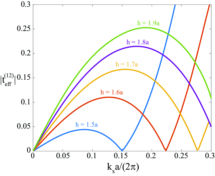
One readily realizes that the effective transmission can be canceled if the second term in Eq. (10) is equal to . In that case, both BWs interfere destructively to cancel the overall leakage, leading to the formation of a BIC. Figure 4 illustrates the interference mechanism as a function of for different values of the slab thickness. For , for symmetry reasons. The second cancellation of is due to destructive interferences. The slab thickness drives the phase difference between both BWs and thus the wave vector value that corresponds to destructive interference increases with .
III.4 Transverse resonance for waves
As the period-to-wavelength ratio is further increased, the third BW becomes propagative, see Fig. 3(b). For and , this corresponds to . In that case, Eqs. (1) become a system. Although more tedious, it is still possible to replace the complex interplay between the three BWs by effective reflection and transmission coefficients.
AS for , let us start the discussion with the case . At the -point, the first and third BWs have a symmetric field profile while the second BW is antisymmetric. The latter is thus decoupled from BWs 1 and 3. Even if three BWs are propagative, the leaky modes of the PhC slab are either formed by the second BW alone (symmetry-protected BIC) or by the interplay between first and third BWs. In that case, we can apply the results from previous section by introducing an effective reflection coefficient instead of . Such a leaky mode formed by BWs 1 and 3 is a BIC if the interference leads to and . This is the case of the blue mode labeled (5) in Figs. 2(f)-(h).
For , the three BWs are coupled and we introduce an effective reflection coefficient , whose closed-form expression can be found in the Supplemental Material. In the process of replacing two BWs by an effective reflection, one keeps the BW that has the most important contribution. The latter is either the second BW or the third BW, depending on the horizontal symmetry of the leaky mode that we want to form.
III.5 Model validation
To validate the multimode Fabry-Perot model, we consider the symmetric 1D PhC slab of Fig. 2(e). We apply the model, either with or BWs and calculate the dispersion curves and quality factors of the different leaky modes supported by the PhC slab. The model prediction for the dispersion curves (not shown here) and for the Q-factors (see Fig. 5) are in quantitative agreement with the rigorous RCWA calculations, which takes into account a large number of evanescent BWs (). In particular, the semi-analytical model accurately predicts all different types of BICs supported by a 1D symmetric PhC slab.
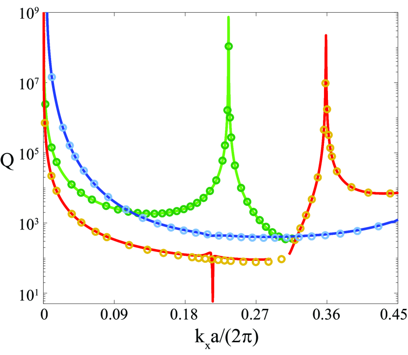
The model also provides some physical insight into the nature of the BICs, which before we could only qualitatively infer from the field profiles. The green mode is mostly given by the second antisymmetric BW, with a small contribution of the fundamental BW for . To calculate it we used from Eq. (9). The blue mode has a quasi-symmetric profile and is dominated by the third BW with a small impact of BWs 1 and 2. For this mode, with the phase factor was used. We can also assert that the BIC at the -point is fundamentally different from the other two, being a resonance-trapped BIC resulting from the destructive interference of BWs one and three. It somewhat harder to distinguish from the symmetry protected one with the exact calculations only, and have been pointed out in the literature before Kodigala et al. (2017). Similarly, the red leaky mode also consists of the three BWs. However, since it couples with a different leaky mode around , it changes its symmetry: from the quasi-antisymmetric one (for ) to the quasi-symmetric one (for ), which is reflected in the BIC field profiles in Fig. 2(h). To correctly apply the model for this case, a slightly different equations are to be used, as was done for the left and right parts of the red curve. Basically, indices and are to be interchanged in the expressions for and the phase matching condition, to reflect the fact that on one side the second BW is dominant, and on the other – the third one. This way, on the left side of the figure becomes equal to at and gives rise to the symmetry-protected BIC. While the other one, at , stems from the interference of the three BWs, the third (symmetric) being the dominant one.
This aspect of the model can be a source of erroneous results. Since we approximate the system, as a resonator with only one wave that has a complex reflection coefficient, phase-matching gives us unperturbed resonances, instead of anti-crossings Bulgakov and Maksimov (2018); Azzam et al. (2018). This is the reason why the model fails in Fig. 5 for the red curve around , where the Rabi splitting occurs and two dispersion curves distance from each other. This point is further illustrated in the Supplemental Material.
Next, we would like now to clarify the obviously erroneous feature of the red curve around . As mentioned above, it is possible to write the phase-matching condition in the from of Eq. (6) under the assumption that the modulus of the reflection coefficient of the mode inside the resonator varies smoothly with the wavelength. This is not, however, necessarily always the case when we deal with effective coefficients. This ‘spike’ corresponds to exactly this situation, when experiences a sudden resonance-like change, which causes phase-matching to fail (see Supplemental Material for an illustration).
All described BICs are robust in the sense that a slight change of one parameter, for example, increase of the thickness, will cause the symmetry-protected resonance red-shift, according to the dispersion relation. In case of the resonance-trapped BICs, they evolve in the whole parameter space.
IV Dynamics of BICs with the slab thickness
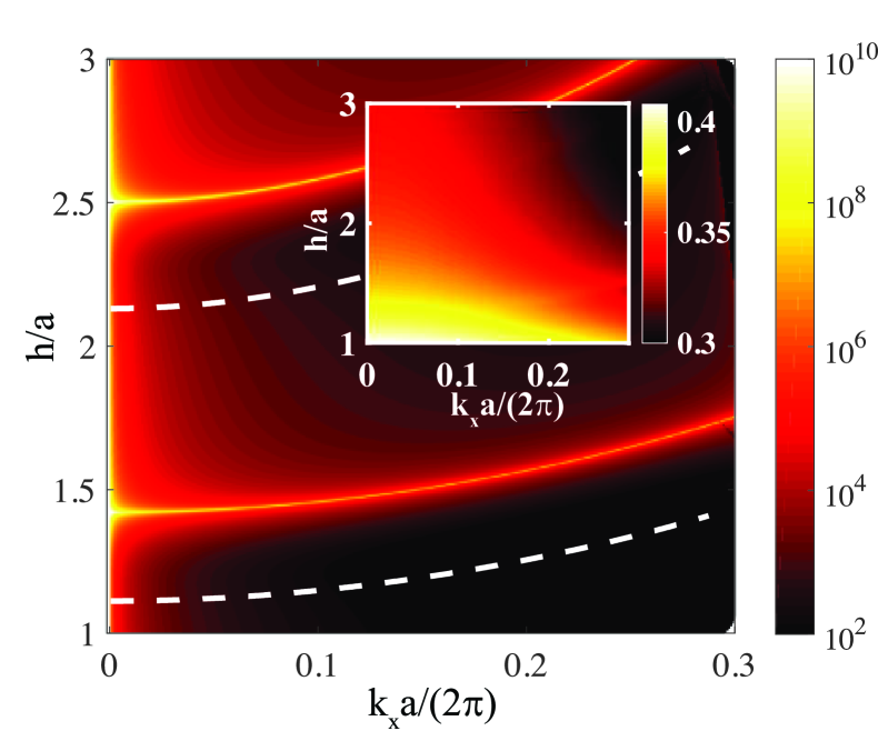
Thanks to the analyticity of the model with respect to the slab thickness, we can apply the model for a large number of values to observe the dynamics of BICs with no additional RCWA calculations. Figure 6 shows the variation of the quality factor of a leaky mode of the PhC slab, in the spectral range between the second and third BW cut-offs, as a function of the thickness and the wave vector . We have chosen the mode represented with the green curve in Fig. 2(f)-(g). The inset shows its dispersion – the values of the normalized frequency .
We can clearly see two branches where equals exactly 1, leading to an infinite -factor. For the values corresponding to this branch, the radiative leakage disappears because two BWs involved interfere destructively. For , the -factor is infinite for any value of , since . It is necessarily a symmetry protected BIC, as the resonance-trapped one is not allowed at below the third BW cut-off. For similar figures in the spectral band where three BWs are propagative, we refer the reader to the Supplemental Material.
V Asymmetric one-dimensional photonic crystal slabs
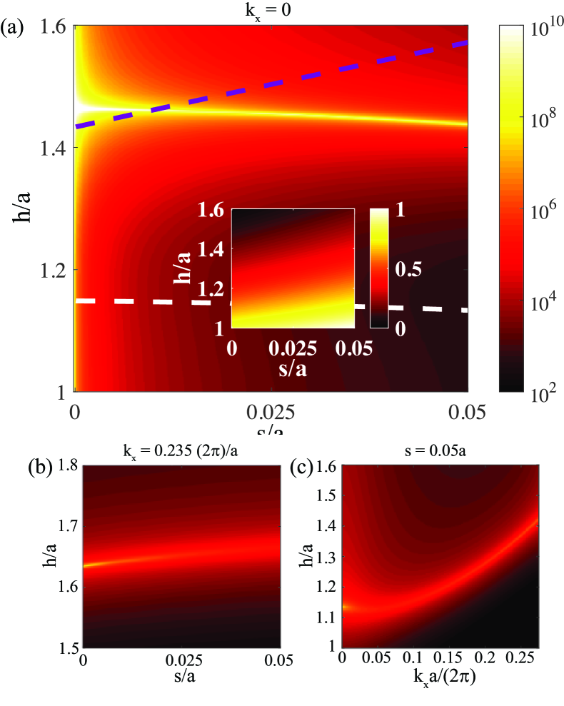
We finally use the multimode Fabry-Perot model to study the behavior of the BICs under broken inversion symmetry. We consider a 1D PhC slab with a vertical mirror symmetry but no horizontal mirror symmetry as depicted in Fig. 1(b). The asymmetry parameter is the size of the air gap that divides the dielectric ridge into a bigger and a smaller parts of sizes and , respectively, after is was split preserving the . Recently, a study of a PhC slab with a slot in different positions, with a fixed thickness and normal incidence angle, has been published Wang et al. (2016a). We evidence that the symmetry-protected BICs that exist in symmetric structures at the -point of the dispersion diagram can still exist when the horizontal mirror symmetry is broken, but only for particular values of the slab thickness.
Figure 7 shows a logarithmic map of a -factor of a leaky mode in different situations. In Fig. 7(a) we plot vs. and for a fixed in a spectral range where only two BWs are propagative. We readily observe a branch that corresponds to a diverging . Under the broken symmetry, no longer vanishes for , which allows us to observe this trajectory of a resonance-trapped BIC. Figure 7(b) has all the same parameters, except that we now set to a specific non-zero value. Namely, such as to get the BIC labeled (2) in Fig. 2(f) for and see how it disappears very rapidly when the symmetry is broken. Lastly, Fig. 7(c) displays -factor of the same mode as a function of and (similarly, as in Fig. 6) with a fixed .
VI Conclusion
We have used a multimode Fabry-Perot model to calculate the dispersion curves and the quality factors of leaky modes supported by 1D symmetric and asymmetric PhC slabs. Leaky modes are transverse Fabry-Perot resonances composed of a few propagative Bloch waves bouncing back and forth vertically inside the slab. This multimode Fabry-Perot model, which does not rely on a perturbative approach, accurately predicts the existence of BICs and their positions in the parameter space regardless of the refractive index contrast. The model equally applies to symmetry-protected BICs (absence of leakage is due to symmetry incompatibility between a single BW composing the mode and the radiative plane waves) and resonance-trapped BICs (radiative leakage accidentally disappears because the contributions of several BWs interfere destructively).
The multimode Fabry-Perot model allows us to show that, regardless of the slab thickness, BICs cannot exist below a cut-off frequency, which is related to the existence of the second-order Bloch wave in the photonic crystal. In other words, BICs cannot exist in the homogenization regime. Thanks to the semi-analyticity of the model, we investigate the dynamics of BICs with the slab thickness in symmetric and asymmetric photonic crystal slabs. We evidence that the symmetry-protected BICs that exist in symmetric structures at the -point of the dispersion diagram can still exist when the horizontal mirror symmetry is broken, but only for particular values of the slab thickness.
Since the multimode Fabry-Perot model yields fast yet accurate predictions of the BIC location in the parameter space and provides a better understanding of the physical mechanisms that lead to the BIC formation, we think that it can become an important tool for designing PhC devices relying on the existence of a BIC.
References
- Joannopoulos, J. D. and Johnson, S. G. and Winn and D. (2008) J. N. Joannopoulos, J. D. and Johnson, S. G. and Winn and M. R. D., Photonic Crystals: Molding the Flow of light, 2nd ed. (Princeton University Press, 2008).
- Sakoda (2005) K. Sakoda, Optical Properties of Photonic Crystals, 2nd ed. (Springer, Berlin, 2005).
- Notomi (2010) M. Notomi, Reports on Progress in Physics 73, 96501 (2010).
- Kuramochi (2016) E. Kuramochi, J. Mater. Chem. C 4, 11032 (2016).
- Baets et al. (2001) R. Baets, B. Demeulenaere, B. Dhoedt, and S. Goeman, “Optical system with a dielectric subwavelength structure having high reflectivity and polarization selectivity,” (2001).
- Mateus et al. (2004) C. F. R. Mateus, M. C. Y. Huang, L. Chen, C. J. Chang-Hasnain, and Y. Suzuki, IEEE Photonics Technology Letters 16, 1676 (2004).
- Ding and Magnusson (2004) Y. Ding and R. Magnusson, Optics Express 12, 5661 (2004).
- Sciancalepore et al. (2013) C. Sciancalepore, B. B. Bakir, S. Menezo, X. Letartre, D. Bordel, and P. Viktorovitch, IEEE Photonics Technology Letters 25, 1111 (2013).
- Inoue et al. (2014) T. Inoue, M. D. Zoysa, T. Asano, and S. Noda, Nature Materials 13, 928 (2014).
- Brongersma et al. (2014) M. L. Brongersma, Y. Cui, and S. Fan, Nature Materials 13, 451 (2014).
- Shen et al. (2015) Y. Shen, V. Rinnerbauer, I. Wang, V. Stelmakh, J. D. Joannopoulos, and M. Soljačić, ACS Photonics 2, 27 (2015).
- Hsu et al. (2013) C. W. Hsu, B. Zhen, J. Lee, S.-L. Chua, S. G. Johnson, J. D. Joannopoulos, and M. Soljacic, Nature 499, 188 (2013).
- Blanchard et al. (2014) C. Blanchard, P. Viktorovitch, and X. Letartre, Physical Review A 90, 33824 (2014).
- Hsu et al. (2016) C. W. Hsu, B. Zhen, A. D. Stone, J. D. Joannopoulos, and M. Soljačić, Nature Reviews Materials 1, 16048 (2016).
- Monticone and Alù (2014) F. Monticone and A. Alù, Physical Review Letters 112, 213903 (2014).
- Von Neuman and Wigner (1929) J. Von Neuman and E. Wigner, Physikalische Zeitschrift 30, 467 (1929).
- Friedrich and Wintgen (1985) H. Friedrich and D. Wintgen, Physical Review A 32, 3231 (1985).
- Yoon et al. (2015) J. W. Yoon, S. H. Song, and R. Magnusson, Scientific Reports 5, 18301 (2015).
- Blanchard et al. (2016) C. Blanchard, J.-P. Hugonin, and C. Sauvan, Physical Review B 94, 155303 (2016).
- Sadrieva et al. (2017) Z. F. Sadrieva, I. S. Sinev, K. L. Koshelev, A. Samusev, I. V. Iorsh, O. Takayama, R. Malureanu, A. A. Bogdanov, and A. V. Lavrinenko, ACS Photonics 4, 723 (2017).
- Kodigala et al. (2017) A. Kodigala, T. Lepetit, Q. Gu, B. Bahari, Y. Fainman, and B. Kanté, Nature 541, 196 (2017).
- Ha et al. (2018) S. T. Ha, Y. H. Fu, N. K. Emani, Z. Pan, R. M. Bakker, R. Paniagua-Domínguez, and A. I. Kuznetsov, Nature Nanotechnology 13, 1042 (2018).
- Liu et al. (2017) Y. Liu, W. Zhou, and Y. Sun, Sensors 17, 1861 (2017).
- Romano et al. (2018) S. Romano, G. Zito, S. Torino, G. Calafiore, E. Penzo, G. Coppola, S. Cabrini, I. Rendina, and V. Mocella, Photonics Research 6, 726 (2018).
- Yesilkoy et al. (2019) F. Yesilkoy, E. R. Arvelo, Y. Jahani, M. Liu, A. Tittl, V. Cevher, Y. Kivshar, and H. Altug, Nature Photonics 13 (2019), 10.1038/s41566-019-0394-6.
- Azzam et al. (2018) S. I. Azzam, V. M. Shalaev, A. Boltasseva, and A. V. Kildishev, Physical Review Letters 121, 253901 (2018).
- Bulgakov et al. (2018) E. N. Bulgakov, D. N. Maksimov, P. N. Semina, and S. A. Skorobogatov, Journal of the Optical Society of America B 35, 1218 (2018).
- Li and Yin (2016) L. Li and H. Yin, Scientific Reports 6, 26988 (2016).
- Wang et al. (2016a) Y. Wang, J. Song, L. Dong, and M. Lu, Journal of the Optical Society of America B 33, 2472 (2016a).
- Wang et al. (2016b) Z. Wang, H. Zhang, L. Ni, W. Hu, and C. Peng, IEEE Journal of Quantum Electronics 52, 1 (2016b).
- Yang et al. (2014) Y. Yang, C. Peng, Y. Liang, Z. Li, and S. Noda, Physical Review Letters 113, 37401 (2014).
- Ni et al. (2016) L. Ni, Z. Wang, C. Peng, and Z. Li, Physical Review B 94, 245148 (2016).
- Yuan and Lu (2017) L. Yuan and Y. Y. Lu, Optics Letters 42, 4490 (2017).
- Gao et al. (2016) X. Gao, C. W. Hsu, B. Zhen, X. Lin, J. D. Joannopoulos, M. Soljačić, and H. Chen, Scientific Reports 6, 31908 (2016).
- Bulgakov and Maksimov (2018) E. N. Bulgakov and D. N. Maksimov, Physical Review A 98, 53840 (2018).
- Fan et al. (2003) S. Fan, W. Suh, and J. D. Joannopoulos, Journal of the Optical Society of America A 20, 569 (2003).
- Fehrembach and Sentenac (2003) A.-L. Fehrembach and A. Sentenac, Journal of the Optical Society of America A 20, 481 (2003).
- Popov et al. (1986) E. Popov, L. Mashev, and D. Maystre, Optica Acta: International Journal of Optics 33, 607 (1986).
- Fehrembach et al. (2002) A.-L. Fehrembach, D. Maystre, and A. Sentenac, Journal of the Optical Society of America A 19, 1136 (2002).
- Lalanne et al. (2006) P. Lalanne, J. P. Hugonin, and P. Chavel, Journal of Lightwave Technology 24, 2442 (2006).
- Karagodsky et al. (2010) V. Karagodsky, F. G. Sedgwick, and C. J. Chang-Hasnain, Optics Express 18, 16973 (2010).
- Karagodsky et al. (2011) V. Karagodsky, C. Chase, and C. J. Chang-Hasnain, Optics Letters 36, 1704 (2011).
- Karagodsky and Chang-Hasnain (2012) V. Karagodsky and C. J. Chang-Hasnain, Optics Express 20, 10888 (2012).
- Koshelev et al. (2018) K. Koshelev, S. Lepeshov, M. Liu, A. Bogdanov, and Y. Kivshar, Physical Review Letters 121, 193903 (2018).
- Moharam et al. (1995) M. G. Moharam, E. B. Grann, D. a. Pommet, and T. K. Gaylord, Journal of the Optical Society of America A 12, 1068 (1995), arXiv:0911.2737 .
- Bai et al. (2013) Q. Bai, M. Perrin, C. Sauvan, J.-P. Hugonin, and P. Lalanne, Optics Express 21, 27371 (2013).
- Lalanne et al. (2019) P. Lalanne, W. Yan, A. Gras, C. Sauvan, J.-P. Hugonin, M. Besbes, G. Demésy, M. D. Truong, B. Gralak, F. Zolla, A. Nicolet, F. Binkowski, L. Zschiedrich, S. Burger, J. Zimmerling, R. Remis, P. Urbach, H. T. Liu, and T. Weiss, Journal of the Optical Society of America A 36, 686 (2019).
- Lalanne et al. (1999) P. Lalanne, S. Astilean, P. Chavel, E. Cambril, and H. Launois, Journal of the Optical Society of America A 16, 1143 (1999).
- Lecamp et al. (2005) G. Lecamp, P. Lalanne, J. P. Hugonin, and J. M. Gérard, IEEE Journal of Quantum Electronics 41, 1323 (2005).
- Haus (1984) H. A. Haus, Waves and fields in optoelectronics (Prentice-Hall International, London, 1984).
- Lalanne et al. (2008) P. Lalanne, C. Sauvan, and J. P. Hugonin, Laser & Photonics Reviews 2, 514 (2008).
- Sauvan et al. (2005) C. Sauvan, P. Lalanne, and J. P. Hugonin, Physical Review B 71, 165118 (2005).
- Note (1) For Bloch-wave-to-plane-wave transmission to disappear due to symmetry incompatibility, the BW has to have an antisymmetric field profile at , in contrast to the symmetric profile of the plane wave. Since the fundamental Bloch wave has a symmetric field profile at , has always a non-zero value.