Relay-aided Random Access for Energy-Limited Devices in the IoT
Abstract
In the Internet-of-Things (IoT), random access is employed for devices to share a common access channel in packet transmission with low signaling overhead. Although a re-transmission strategy is necessary for packet collision resolution, it might be prohibitive for some devices due to energy and complexity constraints. In this paper, we consider a novel relay-aided random access (RARA) scheme where re-transmissions are carried out by relay nodes, not devices. Thanks to multipacket reception with multiple copies of collided signals forwarded by relay nodes, a receiver is able to recover multiple collided packets simultaneously in RARA. As a result, devices of limited complexity and energy source can enjoy reliable transmission using RARA, and the throughput can approach 1 with a large number of relay nodes.
Internet-of-Things (IoT); Random Access; Relay Protocols; Machine-Type Communications (MTC)
I Introduction
A large number of devices are to be connected in the Internet of Things (IoT) and machine-type communication (MTC) has been considered to support devices’ connectivity for the IoT in cellular systems [1] [2] [3]. Due to low signaling overhead, random access is employed for MTC. For example, a multichannel ALOHA based random access scheme is employed in [2]. In [4] [5] [6], various approaches to improve the performance of multichannel ALOHA are considered to be used in MTC.
In random access, the devices that experience collisions can re-transmit collided packets with a certain random backoff strategy [7]. In this case, each device needs to implement a re-transmission scheme with a buffer to keep packets before successful transmissions. However, for devices with limited complexity and energy source, e.g., radio frequency identification (RFID) tags [8], it is often difficult to use re-transmission schemes.
In this paper, we consider the case that devices do not re-transmit collided packets in random access as they have limited energy and complexity (and their transmissions do not necessarily have to be reliable, such as sensors’ transmissions for environmental monitoring with a large number of sensors). This means that no random backoff strategy with buffer is employed at devices. Instead, we use relay nodes to re-transmit collided packets. There have been various relay protocols for cooperative transmissions with relay nodes [9] [10]. While most cooperative communication approaches with relay are considered for coordinated transmissions without contention, there are few approaches for random access, e.g., [11]. Compared with the approach in [11], the proposed approach in this paper can be easily implemented at devices as they do not re-transmit the same packets. Thus, it can be employed for MTC with devices of limited complexity and energy source. However, in the proposed approach, the transmission time can be long and some packets may not be transmitted with a certain probability. Thus, the approach is not suitable for low-latency applications with high reliability.
II System Model
Suppose that there are a number of IoT/MTC devices and one base station (BS) that is a receiver (i.e., we consider uplink transmissions from devices). Each device becomes active when it has a data packet to transmit and random access is considered to share a given radio resource block.
In this paper, we assume that there are relay nodes to help re-transmissions in random access. The resulting scheme is referred to as relay-aided random access (RARA). In RARA, when active devices transmit their packets, we assume that the BS as well as relay nodes receive the signals. For convenience, we assume that the length of packet is normalized. As shown in Fig. 1, suppose that there is no active device in the first session. Then, the BS can wait for a fraction time interval of . Since there is no signal, the BS can initiate the second session (throughout the paper, it is assumed that the BS broadcasts a signal to inform the devices the beginning of a new session). In the second session, there is one active device and there is no collision. The BS can successfully receive the packet from the active device. Subsequently, the BS broadcasts an acknowledgment (ACK) signal at the end of the second session. If there are multiple active devices as in the 4th session, the BS fails to decode the packets due to packet collision and broadcasts an negative-acknowledgment (NACK) signal. In this case, relay nodes sequentially forward their received signals to the BS. This requires unit times, and the devices cannot transmit their packets during the unit times. It is assumed that the relay nodes are ordered in terms of their transmissions in advance to avoid collisions.

For each active device, the session is the time interval (regardless of successful reception) at which the transmission is completed. As shown in Fig. 1, the length of sessions can be (for the state of idle), (for the state of one active device), or (for the state of multiple active devices). Note that to shorten the idle time, can be small, i.e., .
Note that in [11], a relay node is also considered in random access to overcome channel fading with spatial diversity. Thus, the motivation of making use of relay node in [11] differs from that in this paper. In addition, we consider multiple relay nodes and multipacket reception (which are not considered in [11]) to decode multiple collided packets without any complicated temporal backoff strategies at devices and relay nodes. As a result, the RARA scheme becomes quite simple and suitable for MTC with devices of limited complexity and energy source.
III Multipacket Reception
In this section, we discuss the multipacket reception [12] [13] and show that the BS is able to decode the collided signals from up to active devices in RARA.
Suppose that there are active devices in a certain session, say session , where . Let denote the channel coefficient from the th active device to the BS. In addition, let and denote the channel coefficients from the th active device to the th relay node and from the th relay node to the BS, respectively. At the BS, the received signal during session 1 is given by
| (1) |
where is the packet transmitted from the th active device and , , is the background noise during session . According to RARA, the th relay node forwards its signal (using the amplify-forward protocol [9]) at session and the received signal at the BS becomes
| (2) |
where is the signal transmitted by the th relay node that is given by . Here, represents the background noise at the th relay node. In order to overcome packet collisions and successfully decode the signals transmitted by multiple active devices during session 1, the BS can use the received signals in sessions, i.e., .
To illustrate multipacket reception in RARA, for example, we consider the case of (i.e., the case that there is only one relay node). Suppose that there are two active devices in a certain session (i.e., ). The BS fails to decode them due to the packet collision. In the next session, the relay node forwards its received signal that is a superposition of the two signals from the two active devices. The received signals from sessions 1 and 2 at the BS can be written as
| (5) |
where , , and the superscript represents the transpose. If the rank of is 2, can be recovered by multiplying by (ignoring the noise terms). The resulting detector is called the decorrelating detector [15]. We can generalize it to large and where the size of the matrix becomes . As long as the rank of is (with ), the inverse or pseudo-inverse can be used to find for multipacket reception. Other MUD algorithms [15] can be employed to recover from . From this, with a sufficiently high signal-to-noise ratio (SNR), we can see that the BS can decode up to collided signals in RARA. Consequently, throughout the paper, we assume111The performance of multipacket reception in RARA depends on the channel coefficients, , , and . However, for a tractable link-layer performance analysis, we simply assume that multipacket reception becomes successful if . In the future, for a more realistic performance analysis, the performance of multipacket reception is to be taken into account. that the BS is able to decode the signals from up to active devices. Here, becomes a design parameter.
IV Analysis
For performance analysis, we consider the following four states for each session: i) State : idle, i.e., no active device; ii) State : one active device; iii) State : active devices and successful decoding, where ; iv) State : active devices and unsuccessful decoding, where . For convenience, let denote the set of states. Furthermore, we assume a Poisson distribution to model the number of active devices. In particular, the probability of active devices over unit times is given by
| (6) |
where is the traffic intensity per unit time (i.e., the average number of active devices per unit time is ). In addition, for convenience, let , , , and . Since the state of a session depends on the state of the previous session, we have a Markov chain with the following state transition matrix:
| (7) |
where , .
Denote by , , the stationary distribution, and let , where represents the probability that the state of a session is in steady-state. Since , after some manipulations, we can have
| (8) | ||||
| (9) | ||||
| (10) |
where and
Note that once , , and are found, we can obtain and as follows:
For a large , if there are two or more active devices in a session, the state of the next session will be or with a high probability since the session time is long. In particular, according to (6) and (10), we have and as . Furthermore, as , we have
| (11) |
IV-A Outage Probability and Throughput
Let be the probability that there are active devices in a session. Using the stationary distribution, it can be shown that
| (12) |
where , , and if , , and , respectively. If the number of active devices is greater than or equal to in a session, the BS cannot decode the signals although it receives the forwarded signals from relay nodes. The corresponding event is referred to as the outage event and the outage probability is given by
| (13) |
which is a function of and . In general, it is expected to have a low outage probability.
The throughput can be defined as the ratio of the average number of successfully transmitted packets (per session) to the average length of session. The average length of session is given by
| (14) |
The average number of successfully transmitted packets (per session) can be found as
| (15) | ||||
| (16) |
The throughput becomes
| (17) |
which is neither an increasing nor decreasing function of (as can be shown in Fig. 2 (a)).
IV-B Asymptotic Results with
Suppose that is fixed, while . In this case, from [16], we can have the following Gaussian approximation:
| (18) | |||
| (19) | |||
| (20) |
where denotes the cumulative distribution function (cdf) of a Poisson random variable with parameter and represents the cdf of a Gaussian random variable with mean and variance . Since
| (21) |
where and is the Q-function, we have
| (25) |
In addition, since as , by substituting (25) into (16), it can be shown that the asymptotic throughput is given by
| (26) |
The result in (26) demonstrates that the throughput of RARA can approach 1 (with a large and with a sufficiently small ). Since the maximum throughput of slotted ALOHA is [17], we can have a throughput improvement by a factor of thanks to multipacket reception.
Using the Gaussian approximation in (20), for a sufficiently large , we have
| (27) |
which allows us to find the optimal value of that maximizes the throughput for a given large . Since is an increasing function of (for a fixed ), we may expect that the throughput increases and then decreases with . Similarly, for a large , the outage probability can be approximated as
| (28) |
which shows that has to be less than for a low outage probability, which decreases with . In addition, it can be shown that for a fixed , .
V Simulation Results
In this section, we present simulation results under the assumptions in Section IV except that is finite ( is a binomial random variable and ).
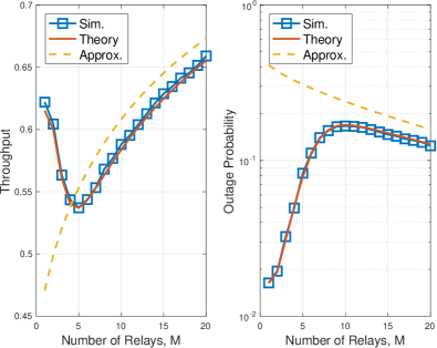
In Fig. 2, we show the throughput and outage probability as functions of the number of relay nodes, , when and . We assume that the number of devices is and each device becomes active (per unit time) with probability . Since the number of devices is large, although the number of devices is a binomial random variable, it can be approximated by a Poisson random variable as in (6). We can see that the theoretical throughput and the outage probability in (17) and (13), respectively, agree with the simulation results, while the approximations in (27) and (28) are also reasonably tight when is sufficiently large.
From Fig. 2 (a), we see that the throughput decreases and then increases with . Thus, it might be necessary to use one relay node () or a number of relay nodes () to achieve a good throughput with a low outage probability as in Fig. 2 (b).
(a) (b)
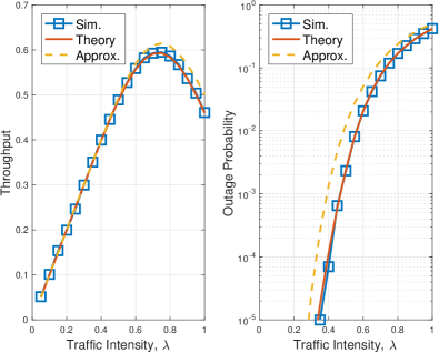
Fig. 3 shows the throughput and outage probability as functions of when and . It is shown that the throughput has a peak at around and the outage probability increases with , which is expected by (28).
(a) (b)
VI Conclusions
In this paper, we proposed a random access scheme, i.e., the RARA scheme, that does not require re-transmissions by devices, but relay nodes for packet collision resolution in MTC. Thanks to relay nodes, it was possible for devices to reliably transmit their packets in random access without employing complicated re-transmission schemes. Thus, the proposed approach can be used for devices of limited complexity and energy source (e.g., RFID tags) in the IoT.
References
- [1] C. Bockelmann, N. Pratas, H. Nikopour, K. Au, T. Svensson, C. Stefanovic, P. Popovski, and A. Dekorsy, “Massive machine-type communications in 5G: physical and MAC-layer solutions,” IEEE Communications Magazine, vol. 54, pp. 59–65, September 2016.
- [2] 3GPP TR 37.868 V11.0, Study on RAN improvments for machine-type communications, October 2011.
- [3] 3GPP TS 36.321 V13.2.0, Evolved Universal Terrestrial Radio Access (E-UTRA); Medium Access Control (MAC) protocol specification, June 2016.
- [4] O. Arouk and A. Ksentini, “Multi-channel slotted aloha optimization for machine-type-communication,” in Proc. of the 17th ACM International Conference on Modeling, Analysis and Simulation of Wireless and Mobile Systems, pp. 119–125, 2014.
- [5] J. Choi, “On the adaptive determination of the number of preambles in RACH for MTC,” IEEE Communications Letters, vol. 20, pp. 1385–1388, July 2016.
- [6] L. Liu, E. G. Larsson, W. Yu, P. Popovski, C. Stefanovic, and E. de Carvalho, “Sparse signal processing for grant-free massive connectivity: A future paradigm for random access protocols in the Internet of Things,” IEEE Signal Processing Magazine, vol. 35, pp. 88–99, Sept 2018.
- [7] L. Dai, “Stability and delay analysis of buffered aloha networks,” IEEE Trans. Wireless Communications, vol. 11, pp. 2707–2719, August 2012.
- [8] D. M. Dobkin, The RF in RFID, Second Edition: UHF RFID in Practice. Newton, MA, USA: Newnes, 2nd ed., 2012.
- [9] J. Laneman, D. Tse, and G. Wornell, “Cooperative diversity in wireless networks: Efficient protocols and outage behavior,” IEEE Trans. Inform. Theory, vol. 50, pp. 3062–3080, Dec. 2004.
- [10] E. Hossain, D. I. Kim, and V. K. Bhargava, Cooperative Cellular Wireless Networks. Cambridge University Press, 2011.
- [11] A. A. El-Sherif and K. J. R. Liu, “Cooperation in random access networks: Protocol design and performance analysis,” IEEE Journal on Selected Areas in Communications, vol. 30, pp. 1694–1702, October 2012.
- [12] S. Ghez, S. Verdu, and S. C. Schwartz, “Stability properties of slotted Aloha with multipacket reception capability,” IEEE Trans. Automatic Control, vol. 33, pp. 640–649, July 1988.
- [13] M. K. Tsatsanis, , and S. Banerjee, “Network-assisted diversity for random access wireless networks,” IEEE Trans. Signal Processing, vol. 48, pp. 702–711, March 2000.
- [14] G. Bartoli, N. C. Beaulieu, R. Fantacci, and D. Marabissi, “An effective multiuser detection scheme for MPR random access networks,” IEEE Trans. Communications, vol. 65, pp. 1119–1130, March 2017.
- [15] S. Verdu, Multiuser Detection. Cambridge University Press, 1998.
- [16] D. J. C. MacKay, Information Theory, Inference, and Learning Algorithms. Cambridge University Press, 2003.
- [17] B. Bertsekas and R. Gallager, Data Networks. Englewood Cliffs: Prentice-Hall, 1987.