Multimode fiber based single-shot full-field measurement of optical pulses
Abstract
Multimode fibers are widely explored for optical communication, imaging and sensing applications. The interference of fiber guided modes generates a speckle pattern, which has been used for high-precision spectroscopy, temperature, and strain sensing. Here we demonstrate a single-shot full-field temporal measurement technique based on a multimode fiber. The complex spatiotemporal speckle field is created by a reference pulse propagating through the fiber, and it interferes with a signal pulse. From the time-integrated interference pattern, both the amplitude and the phase of the signal are retrieved in spectral and temporal domains. The simplicity and high sensitivity of our scheme illustrate the potential of multimode fibers as versatile and multi-functional sensors.
I Introduction
A multimode fiber (MMF) can be considered as a complex photonic structure Rotter17 ; Mosk12 with diverse degrees of freedom in space, time, spectrum and polarization. As these degrees of freedom are coupled, an MMF provides a versatile and multi-functional platform for communication Richardson13 ; Kahn17 , imaging Papadopoulos12 ; Caravaca-Aguirre13 ; Ploschner15 ; French18 and sensing applications Fujiwara12 ; Wang06 ; Liu07 ; Redding12 ; Redding14 ; Valley16 ; Sefler18 . The abundant spatial degrees of freedom have been utilized for controlling linear Carpenter15 ; Xiong16 ; Xiong17 ; Ambichl17 and nonlinear light propagation Wright15 ; Florentin17 ; Tzang18 ; Chekhovskoy18 ; Krupa19 in an MMF. The spatial, temporal, spectral or polarization states of transmitted light are manipulated by shaping the spatial wavefront of an incident beam. Hence, an MMF can function as a microscope Papadopoulos12 ; Caravaca-Aguirre13 ; Ploschner15 ; French18 , a reconfigurable waveplate 2018_Xiong_LSA or a pulse shaper Carpenter15 ; Xiong16 ; Xiong17 ; Ambichl17 . In particular, the coupling between spatial and temporal degrees of freedom in an MMF enables tailoring the output state in time by manipulating the input state in space. However, the reverse process, i.e., extracting the input temporal shape from the output spatial profile of an MMF, has not been explored. It will open the possibility of using an MMF for temporal pulse measurement.
MMFs have already been employed for various sensing applications. For example, an MMF can be implemented to detect changes in temperature, refractive index and strain Okamoto88 ; Fujiwara12 ; Wang06 ; Liu07 , because the speckle pattern, produced by the interference of guided modes, is sensitive to external perturbations. For optical coherence tomography (OCT), random temporal speckles generated by MMFs are used to image axial reflectivity profiles Villiger17 . Furthermore, the dependence of the output spatial pattern on the input spectrum is utilized to transform an MMF into a compact and high-resolution spectrometer Redding12 ; Redding14 . However, only the spectral amplitude can be extracted in the spatial intensity pattern, not the spectral phase, which is needed for full-field temporal measurement.
In this work, we propose and realize a novel method based on an MMF for single-shot full-field measurement of optical pulses. It utilizes the complex yet deterministic spatiotemporal speckle field produced by a reference pulse propagating through an MMF. Such field , which is two-dimensional (2D) in space and one-dimensional (1D) in time , interferes with the unknown field of a signal pulse that is mutually coherent with . The interference pattern is integrated in time by a camera. From this pattern, both the spectral amplitude and the phase of the signal are retrieved. The Fourier transform gives the full field of . The temporal resolution is set by the temporal speckle size, which is inversely proportional to the spectral bandwidth of the reference pulse . The temporal range of a single-shot measurement, , is set by the temporal length of the transmitted waveform, which is given by the inverse of the spectral correlation width of the MMF. A fiber with stronger modal dispersion has faster spectral decorrelation, thus covering a longer time window.
Our scheme can be considered as parallel ghost imaging in time Devaux16 . Compared to the conventional ghost imaging that relies on the sequential generation of different temporal waveforms Shirai10 ; Chen13 ; Ryczkowski16 , the MMF simultaneously creates many distinct temporal speckle patterns, each at a different spatial location of the output facet, to sample the signal. The parallel sampling enables single-shot measurement, eliminating the requirement for repetitive signals.
II Result
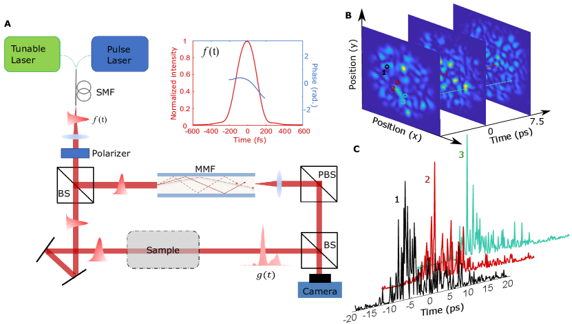
The proposed scheme is experimentally demonstrated in a Mach-Zehnder interferometric setup shown schematically in Fig. 1A. A 230-fs-long pulse from a mode-locked near-IR fiber laser (NKT, Onefive Origami) is split by a beam splitter into two paths, one is launched into the MMF for creation of the spatio-temporal speckle field , and the other is sent to probe a sample placed in the other arm of the interferometer. The transmitted or reflected field from the sample is combined with by a second beam splitter. Since they are mutually coherent, they will interfere, as long as overlaps with in time, which is ensured by matching the optical path lengths of the two arms of the interferometer. To increase the temporal length of , which determines the measurement range, we adjust the launch condition for the reference pulse into the MMF so that it excites many guided modes that propagate at different speeds. Due to modal dispersion, the transmitted pulse is broadened and distorted. The pulse shape varies spatially across the fiber facet. To have strong modal dispersion, we choose a step-index fiber (105 m core, 0.22 NA, Thorlabs FG105LCA) of 1.8-meter length.
To calibrate the spatiotemporal speckle at the fiber output, we measure the transmitted field profile in the spectral domain with a tunable continuous-wave (CW) fiber laser. The laser wavelength is scanned from nm to nm with a step of 0.2 nm. This range fully covers the spectrum of the reference pulse, which is centered at nm and has a full width at half maximum (FWHM) nm, as reported in the Supplementary Materials, Section S1. To ensure the launch condition of the CW laser light into the MMF is identical to that of the pulsed laser, the outputs from both lasers are coupled into a single-mode fiber (SMF) switch. The CW light transmitted through the MMF is combined with that from the reference arm at a slight angle, producing spatial interference fringes. By applying a Hilbert filter in the Fourier domain of the recorded interference pattern, the amplitude and phase of the transmitted field at a single frequency are extracted. Scanning the frequency of the CW laser and repeating this off-axis holography measurement gives the frequency-resolved field transmission matrix . At both the input and the output of the MMF, only one polarization is selected.
After calibrating of the MMF with the tunable CW laser, the input source is switched to a pulsed laser. The reference pulses are characterized by an autocorrelator and an optical spectrum analyzer (see details in the Supplementary Materials, Section S1). From these measurements, the spectral amplitude and phase of the reference field are obtained. The Fourier transform gives the temporal waveform of the reference pulse that is injected into the MMF. The temporal shape and phase of the reference pulse are shown in the inset of Fig. 1A. The transmitted field of the MMF is in frequency, and in time. As shown in Fig. 1B, the output speckle pattern changes rapidly in time. At each spatial location, the distinct temporal waveform is composed of multiple speckles, as plotted in Fig. 1C.
The complex yet deterministic spatiotemporal speckles generated by the MMF enable single-shot full-field measurement of the unknown signal by interfering and . The time-integrated interference pattern is recored by off-axis holography, . The information of is encoded in the interference term . is extracted with the same Hilbert filter used in the calibration of . In the frequency domain, the interference term is , where is the Fourier transform of . This expression can be rewritten as a linear product of a matrix and a vector:
| (1) |
With and known, is retrieved from by an iterative optimization algorithms. To account for temporal or spectral sparsity of , we deploy a compressive sensing algorithm FASTA Goldstein14 to solve the sparse least square optimization problem.
To find the temporal resolution, we compute the temporal correlation function of the spatiotemporal speckle field, , where denotes averaging over and . The FWHM of gives the average temporal speckle size fs, which determines the temporal resolution.
The temporal range of measurement is equal to the temporal length of , which is inversely proportional to the width of the spectral correlation function . From the width of , we estimate to be about 35 ps. The time bandwidth product (TBP), defined by the ratio of the temporal range to the temporal resolution, is .
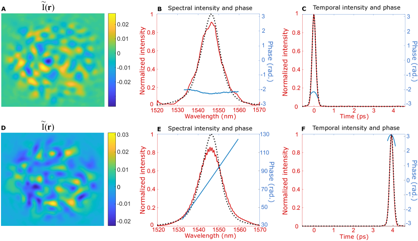
We first test our method by measuring single pulses propagating through the reference arm (without a sample) of the Mach-Zehnder interferometer with different delay times. By changing the length of the reference arm with a delay line, we vary the arrival time of the pulse. The zero delay time is set by the arrival time of the pulse when the length of the reference arm is matched to that of the fiber arm. Figure 2 shows the measurement results for two delay times (top row) and ps (bottom row). The left column shows the interference term extracted from the experimentally measured hologram in these two cases. Although the pulse shape remains the same, the spatial interference pattern is very different. It is because pulses with varying delays interfere with different parts of the spatiotemporal speckles from the MMF. The retrieved intensity and phase of the pulses in wavelength and time domains are plotted in the second and third columns. The recovered spectral intensity is consistent with the measurement using an optical spectral analyzer. While the recovered spectral phase is flat for , it changes linearly for ps. These results are expected, as the slope of the spectral phase corresponds to the delay time. In the time domain, the arrival times of the recovered pulses agree with the values set by the delay line, and the temporal pulse shape is consistent with the autocorrelation trace (see Section S1 in the Supplementary Materials).
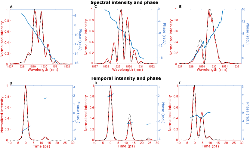
We next measure double pulses. Unstable double-pulsing is a common phenomenon for lasers that are over-pumped, but it is difficult to detect with repetitive measurement techniques that rely on stable pulse trains. Our method can measure double pulses in a single shot. To produce double pulses, we first create 2.2-ps-long pulses by spectral filtering the output from a mode-locked fiber laser (Calmar Mendocino) (see the Supplementary Materials, Section S1). Then we insert a double-side-polished silicon wafer to the reference arm of the March-Zehnder interferometer as the sample. An incident pulse is reflected back and forth between the two surfaces of the wafer, creating multiple pulses in transmission. The distance between the pulses is determined by the wafer thickness and the incident angle. Fig. 3A shows the recovered spectral intensity, which exhibits a rapid oscillation. To verify the result, we also simulate the transmission spectrum of the silicon wafer using the transfer matrix method. The wafer thickness is 535 m and the incident angle of the probe pulse is 1 degree (see the Supplementary Materials, Section S2). The simulated spectrum (black dotted line) agrees well with the recovered spectrum (red solid line). The recovered spectral phase, unwrapped and plotted by the blue solid line, features descending jumps at the frequencies of local minima for the spectral intensity. These phase jumps, together with the amplitude oscillations, are results of spectral interference of the double pulse, which is reconstructed from the Fourier transform of the recovered spectral field in Fig. 3B. The first pulse originates from direct transmission of the probe pulse through the wafer and the second pulse from two reflections within the wafer. They are spaced by 12.5 ps, which is consistent with the 3.75-mm-long one-round-trip optical path length. Because of the relatively low reflectivity of the silicon-air interface, the intensity ratio of the first pulse to the second pulse is 17.6. Although the second pulse is rather weak, it can still be recovered by our scheme, and the temporal shape agrees well with the simulation result. The temporal phases of the two pulses vary linearly, reflecting the absence of frequency chirp within each pulse.
Finally, we measure more complex pulses that are created by reflection from a silicon wafer. The interferometric setup is slightly modified to measure the pulses reflected by the sample in the reference arm (see the Supplementary Materials, Section S3). The recovered spectral intensity in Fig. 3C features interference fringes of higher contrast, and the spectral phase exhibits larger jumps than those in Fig. 3A. The Fourier transform of the recovered spectral field reveals three pulses in the time domain, as plotted in Figure 3. The first pulse results from the direct reflection of the incident pulse by the front surface of the wafer, and the second pulse from direct reflection by the back surface. The intensity ratio of the second pulse to the first pulse in reflection is higher than that in transmission, leading to more pronounced interference fringes in the spectral domain. Nevertheless, the frequency spacing of the fringes, which is determined by the delay time between the two pulses, remains the same. Even the third pulse, generated by three reflections in the wafer, is still visible and recovered in our measurement. The recovered spectral and temporal intensities are in good agreement with the simulation results. The temporal phase within each of the three pulses increases linearly in time with the same slope, indicating each pulse has the same frequency and no chirp.
To reduce the pulse spacing, we switch to a second wafer of a smaller thickness (212 m). The reconstructed pulses in reflection are shown in Fig. 3F. The delay time between adjacent pulses is reduced to 5 ps, corresponding to one round-trip in the silicon wafer. However, the relative intensities of the three pulses are not changed, as they are determined by the reflectivity of the silicon-air interface. The shorter delay time corresponds to the larger spacing of spectral fringes, leading to a smaller number of fringes within the same frequency range in Fig. 3E. The recovered pulses have a slight overlap in time, again in good agreement with the simulation result.
III Discussion
In summary, we demonstrate a novel MMF-based scheme for the single-shot full-field measurement of complex pulses. We obtain a temporal resolution of fs, a temporal range of 35 ps and a TBP of 152. The temporal resolution can be further enhanced by increasing the spectral bandwidth of the reference pulse. The temporal range of the single-shot measurement, which is governed by the spectral correlation width of the MMF, may be tuned independently of the temporal resolution. For example, using a 100-meter-long MMF will increase the temporal range to nanosecond Redding14 . The TBP is limited by the number of guided modes in the MMF, which may well exceed 1000 for a fiber with a large core and a high numerical aperture. Using a bundle of MMFs will further increase the TBP Liew16 .
Taking full advantage of the complex spatio-temporal speckles created by the reference pulse through an MMF, our scheme eliminates the mechanical scanning of the time delay between the signal and the reference. Furthermore, our method overcomes the limitation of spectral resolutions in spectral interferometry Froehly73 ; Lepetit95 ; Dorrer99 ; Dorrer00 . Comparing to other single-shot methods based on nonlinear processes such as time lens Iaconis98 ; shea01 ; Li17 ; Ryczkowski18 ; Tikan18 , our scheme is based on linear interferometry, which possesses a much higher sensitivity. With the knowledge of the reference pulse, as required by all linear interferometric methods Monmayrant10 , it can measure non-reproducible and non-periodic ultra-weak signals. The reference pulse is not necessarily transform-limited, as long as its temporal/spectral amplitude and phase are known. Even without knowledge of the reference, the relative phase and amplitude change imposed by the sample can still be recovered (see Section S4 in the Supplementary Materials). The simplicity and high sensitivity of our method illustrate the potential of MMFs as versatile and multi-functional sensors.
IV Supplementary Materials
Supplementary materials for this article are available at xxxx.
Section S1. Calibrations of reference pulses.
Section S2. Characterizations of silicon wafer samples.
Section S3. Setup of the reflection measurement.
Section S4. Measuring sample properties without a known reference pulse.
Fig. S1. Calibration of the NKT laser.
Fig. S2. Calibration of the Calmar laser.
Fig. S3. Transmission and reflection spectra of two silicon wafers.
Fig. S4. Schematics of the reflection measurement setup.
References
- (1) S. Rotter, S. Gigan, Light fields in complex media: Mesoscopic scattering meets wave control. Rev. Mod. Phys. 89, 015005 (2017).
- (2) A. P. Mosk, A. Lagendijk, G. Lerosey, M. Fink, Controlling waves in space and time for imaging and focusing in complex media. Nat. Photon. 6, 283 (2012).
- (3) D. J. Richardson, J. M. Fini, L. E. Nelson, Space-division multiplexing in optical fibres. Nat. Photon. 7, 354 (2013).
- (4) J. M. Kahn, D. A. Miller, Communications expands its space. Nat. Photon. 11, 5 (2017).
- (5) I. N. Papadopoulos, S. Farahi, C. Moser, D. Psaltis, Focusing and scanning light through a multimode optical fiber using digital phase conjugation. Opt. Express 20, 10583-10590 (2012).
- (6) A. M. Caravaca-Aguirre, E. Niv, D. B. Conkey, R. Piestun, Real-time resilient focusing through a bending multimode fiber. Opt. Express 21, 12881-12887 (2013).
- (7) M. Plöschner, T. Tyc, T. Čižmár, Seeing through chaos in multimode fibres. Nat. Photon. 9, 529 (2015).
- (8) R. French, S. Gigan, O. L. Muskens, Snapshot fiber spectral imaging using speckle correlations and compressive sensing. Opt. Express 26, 32302-32316 (2018).
- (9) T. Okamoto, I. Yamaguchi, Multimode fiber-optic Mach-Zehnder interferometer and its use in temperature measurement. Appl. Opt. 27, 3085-3087 (1988).
- (10) Q. Wang, G. Farrell, All-fiber multimode-interference-based refractometer sensor: proposal and design. Opt. Lett. 31, 317-319 (2006).
- (11) Y. Liu, L. Wei, Low-cost high-sensitivity strain and temperature sensing using graded-index multimode fibers. Appl. Opt. 46, 2516-2519 (2007).
- (12) E. Fujiwara, Y. T. Wu, C. K. Suzuki, Vibration-based specklegram fiber sensor for measurement of properties of liquids. Optics and Lasers in Engineering 50, 1726-1730 (2012).
- (13) B. Redding, H. Cao, Using a multimode fiber as a high-resolution, low-loss spectrometer. Opt. Lett 37, 3384-3386 (2012).
- (14) B. Redding, M. Alam, M. Seifert, H. Cao, High-resolution and broadband all-fiber spectrometers. Optica 1, 175-180 (2014).
- (15) G. C. Valley, G. A. Sefler, T. J. Shaw, Multimode waveguide speckle patterns for compressive sensing. Opt. Lett. 41, 2529-2532 (2016).
- (16) G. A. Sefler, T. J. Shaw, G. C. Valley, Demonstration of speckle-based compressive sensing system for recovering RF signals. Opt. Express 26, 21390-21402 (2018).
- (17) J. Carpenter, B. J. Eggleton, J. Schröder, Observation of Eisenbud–Wigner–Smith states as principal modes in multimode fibre. Nat. Photon. 9, 751 (2015).
- (18) W. Xiong, P. Ambichl, Y. Bromberg, B. Redding, S. Rotter, H. Cao, Spatiotemporal control of light transmission through a multimode fiber with strong mode coupling. Phys. Rev. Lett. 117, 053901 (2016).
- (19) W. Xiong, P. Ambichl, Y. Bromberg, B. Redding, S. Rotter, H. Cao, Principal modes in multimode fibers: exploring the crossover from weak to strong mode coupling. Opt. Express 25, 2709-2724 (2017).
- (20) P. Ambichl, W. Xiong, Y. Bromberg, B. Redding, S. Rotter, H. Cao,Super-and Anti-Principal-Modes in Multimode Waveguides. Phys. Rev. X 7, 041053 (2017).
- (21) L. G. Wright, D. N. Christodoulides, F. W. Wise, Controllable spatiotemporal nonlinear effects in multimode fibres. Nat. Photon. 9, 306 (2015).
- (22) O. Tzang, A. M. Caravaca-Aguirre, K. Wagner, R. Piestun, Adaptive wavefront shaping for controlling nonlinear multimode interactions in optical fibres. Nat. Photon. 12, 368–374 (2018).
- (23) I. S. Chekhovskoy, A. M. Rubenchik, O. V. Shtyrina, M. A. Sorokina, S. Wabnitz, M. P. Fedoruk, Nonlinear discrete wavefront shaping for spatiotemporal pulse compression with multicore fibers. JOSA B 35, 2169-2175 (2018).
- (24) R. Florentin, V. Kermene, J. Benoist, A. Desfarges-Berthelemot, D. Pagnoux, A. Barthélémy, J. P. Huignard, Shaping the light amplified in a multimode fiber. Light Sci. Appl. 6, e16208 (2017).
- (25) K. Krupa, V. Couderc, A. Tonello, D. Modotto, A. Barthélémy, G. Millot, S. Wabnitz, Refractive index profile tailoring of multimode optical fibers for the spatial and spectral shaping of parametric sidebands. JOSA B, 36, 1117-1126 (2019).
- (26) W. Xiong, C. W. Hsu, Y. Bromberg, J. .E. Antonio-Lopez, R. A. Correa, H. Cao, Complete polarization control in multimode fibers with polarization and mode coupling. Light Sci. Appl. 7, 54 (2018).
- (27) M. Villiger, P. C. Hui, N. Uribe-Patarroyo, B. E. Bouma, Imaging reflectivity profiles with random axial encoding. Photonics Conference, IEEE 299-300 (2017).
- (28) F. Devaux, P. A. Moreau, S. Denis, E. Lantz, Computational temporal ghost imaging. Optica 3, 698-701 (2016).
- (29) T. Shirai, T. Setälä, A. T. Friberg, Temporal ghost imaging with classical non-stationary pulsed light. JOSA B 27, 2549-2555 (2010).
- (30) Z. Chen, H. Li, Y. Li, J. Shi, G. Zeng, Temporal ghost imaging with a chaotic laser. Opt. Eng. 52, 076103 (2013).
- (31) P. Ryczkowski, M. Barbier, A. T. Friberg, J. M. Dudley, G. Genty, Ghost imaging in the time domain. Nat. Photon. 10, 167 (2016).
- (32) T. Goldstein, C. Studer, R. Baraniuk, A field guide to forward-backward splitting with a FASTA implementation. arXiv:1411.3406 (2014).
- (33) S. F. Liew, B. Redding, M. A. Choma, H. D. Tagare, H. Cao, Broadband multimode fiber spectrometer. Opt. Lett. 41, 2029-2032 (2016).
- (34) C. Froehly, A. Lacourt, J. C. Vienot, Notions de réponse impulsionnelle et de fonction de transfert temporelles des pupilles optiques. J. d’optique 4, 183-196 (1973).
- (35) L. Lepetit, G. Chériaux, M. Joffre, Linear techniques of phase measurement by femtosecond spectral interferometry for applications in spectroscopy. JOSA B 12, 2467-2474 (1995).
- (36) C. Dorrer, Influence of the calibration of the detector on spectral interferometry. JOSA B 16, 1160-1168 (1999).
- (37) C. Dorrer, N. Belabas, J. p. Likforman, M. Joffre, Spectral resolution and sampling issues in Fourier-transform spectral interferometry. JOSA B 17, 1795-1802 (2000).
- (38) P. R. Griffiths, J. A. De Haseth, Fourier transform infrared spectrometry (John Wiley & Sons 2007), Vol. 171.
- (39) C. Iaconis, I. A. Walmsley, Spectral phase interferometry for direct electric-field reconstruction of ultrashort optical pulses. Opt. Lett. 23, 792-794 (1998).
- (40) P. O’shea, M. Kimmel, X. Gu, R. Trebino, Highly simplified device for ultrashort-pulse measurement. Opt. Lett. 2626, 932-934 (2001).
- (41) B. Li, S. W. Huang, Y. Li, C. W. Wong, K. K. Wong, Panoramic-reconstruction temporal imaging for seamless measurements of slowly-evolved femtosecond pulse dynamics. Nat. Commun. 8, 61 (2017).
- (42) P. Ryczkowski, M. Närhi, C. Billet, J. M. Merolla, G. Genty, J. M. Dudley, Real-time full-field characterization of transient dissipative soliton dynamics in a mode-locked laser. Nat. Photon. 12, 221 (2018).
- (43) A. Tikan, S. Bielawski, C. Szwaj, S. Randoux, P. Suret, Single-shot measurement of phase and amplitude by using a heterodyne time-lens system and ultrafast digital time-holography. Nat. Photon. 12, 228 (2018).
- (44) A. Monmayrant, S. Weber, B. Chatel, A newcomer’s guide to ultrashort pulse shaping and characterization. J. Phys. B 43, 103001 (2010).
V Acknowledgment
The authors acknowledge Chia Wei Hsu, Yaniv Eliezer, Logan Wright for fruitful discussions.
Funding: This work is supported by US National Science Foundation under the Grant Nos. ECCS-1509361 and ECCS-1809099.
Author contributions: W. X conducted the experiment, simulation, and computational algorithms. S. G. contributed to the development of algorithms. H. Y. prepared the wafer samples and contributed to the measurement. H. C. initiated and supervised the project. W. X. and H. C wrote the manuscript with feedback from S. G. and H. Y.
Competing interests: The authors declare that they have no competing interests.
Data availability: All data necessary to evaluate the conclusions in the paper are present in the paper and/or the Supplementary Materials. Additional data related to this paper may be requested from the authors.
See pages , 1, , 2, , 3, , 4, of SM.pdf