Effect of black hole–plasma system on light beams
Matej Sárený111matej.sareny@gmail.com and Vladimír Balek222balek@fmph.uniba.sk
Department of Theoretical Physics, Comenius University,
Bratislava, Slovakia
Abstract
In the paper we discuss propagation of light around Kerr black hole surrounded by non-magnetized cold plasma with infinite conductivity. For that purpose, we use equations for propagation of light rays obtained within Synge’s approach in the approximation of geometrical optics. We derive equation of deviation of a ray propagating close to the reference ray, which is a generalization of the well-known Jacobi equation, and use it to calculate the modification of angular distribution of stars observed close to a black hole surrounded by plasma, compared to the uniform star distribution that would be seen without black hole or plasma. We place the observer in the equatorial plane of the Kerr black hole and try various choices of plasma distributions described by mathematically simple formulae. Key features of star distribution on a local sky near the black hole are identified and the influence of plasma on them is discussed.
Keywords: relativistic geometric optics in plasma, ray equation, ray deviation, star distribution function
1 Introduction
The focus of our paper is the behavior of light rays in the vicinity of a rotating uncharged black hole (BH) in the presence of plasma. Since the discovery of Kerr metric [1] in 1963, the behavior of light rays around such BH has been intensively studied by many authors. Geodesics around the Kerr BH were investigated for example in [2, 3] and detailed discussion of spherical orbits can be found in [4]. For an observer at arbitrary position, some of the light rays are arriving “from the BH” (i.e. no rays from distant stars can arrive from that direction), forming the apparent “shadow” of the BH. The shape of the shadow was investigated in [5, 6]. For an observer close to the BH, the look of the night sky is distorted due to the bending of the light rays. Such photographs were simulated in [7, 8] using backward ray-tracing. Also, the appearance of the accretion disc around the BH, as seen by the observer outside the disc, was studied numerically [7, 9, 10, 11].
The inclusion of optical effects of the plasma around the BH, potentially present in the form of accretion disc, or a spherical cloud of dilute material gathered from cosmic environment, can be made by utilizing Synge’s geometrical optics for an isotropic medium with non-unit index of refraction [12]. Lately, this approach is being intensively applied in many papers. Effects of plasma around a non-rotating BH were investigated in [13, 14, 15, 16], including changes in deflection angle, shadow of the BH, magnification factor in gravitational lensing etc., and additional effects arising in Kerr metric were studied in [6, 17, 18, 19]. In particular, the influence of plasma on the apparent shadow of the BH was explored in [6, 19, 20]. As it turns out, among the properties of plasma only one function, the density of electrons, has an effect on light rays, while the 4-velocity of plasma drops out of the equations entirely. Besides, the trajectory of photon depends on its frequency due to the dispersive properties of plasma. The most commonly used “toy models” for plasma distribution are homogeneous plasma [14, 17, 19, 22, 23], singular and nonsingular isothermal sphere [13, 24] and a sphere with power law distribution [13, 16, 17, 19, 20, 22, 23, 24, 25]. Also, it would be interesting to consider disc-like distributions where the disc’s middle plane coincides with equatorial plane of the Kerr BH. Realistic models of accretion discs are not commonly used because of their intricate nature, involving discontinuities of various types and uncertainty in the vertical profile. The models also raise physical questions about the validity of geometrical optics in a disc due to its optical thickness in most cases, as well as its own radiation outshining any light rays from distant stars that would propagate through it. The theoretical work on accretion discs is reviewed in [26]; the most popular models include thin discs [27, 28, 29, 30], advection dominated discs [31, 32] and Polish doughnuts [33].
The body of the paper is divided into four sections. In the second section we rewrite Synge’s equations into Lagrangian form, obtaining equations of motion (EoMs) for the light ray in plasma with such parametrization that coincides with the wave 4-vector. We build on this to derive ray deviation equation (RDE), which is a generalization of equation of geodesic deviation known from textbooks on general relativity. We also discuss the conservation laws for the case of Kerr BH surrounded by stationary axially-symmetrically distributed non-gravitating plasma. In the third section we introduce the star distribution function (SDF), which measures the angular dependence of star density as viewed by an observer influenced by light bending in constrast to an observer who sees homogeneous sky. In the fourth section we develop tools for calculating the SDF numerically, following techniques from [7, 34, 35]. Furthermore, we discuss technical details of our calculations, including observer specification, initial conditions, plasma distribution “toy models” and some specifics of our code. In the fifth section we discuss various features of SDF as obtained in our calculations.
Throughout the paper we use the signature with Greek spacetime indices and Latin spatial indices. Our other notations follow the textbook [36]: we use the symbols for exterior derivative, for Lie derivative and for the metric-compatible, torsion-free covariant derivative, and adopt “music notation” and for abstract lowering and rising of indices. In index notation, these operators are , , , and , where is scalar, , are vectors, is covector, is tensor of an arbitrary rank and are coefficients of affine connection. (We restrict ourselves to the expressions used in the article, therefore we do not write how and act on general tensors, just define their action on scalars and vectors respectively.) We also utilize the geometrized unit convention , and when considering Kerr geometry we set (the mass of Kerr black hole) .
2 Equations of motion for light rays in the presence of plasma
2.1 Equation of motion for a single ray
Geometrical optics for isotropic media is developed in the book by Synge [12] in Hamilton – Jacobi formalism. The basic object is the eikonal , which satisfies the equation
| (1) |
where is refraction index of the medium and is its 4-velocity. In terms of the eikonal, the wave 4-vector at any given point is defined as . For an observer carrying a clock, a ruler and a protractor described by an orthonormal tetrad , the components and give us the frequency and the wave vector respectively, hence is minus the frequency as observed in the medium rest frame.
The characteristics of the eikonal equation are called light rays and are given by the Hamilton equations following from the Hamiltonian
| (2) |
Since the Hamiltonian is independent on the parameter of the ray , it must be constant, and from its definition it follows that its only physically acceptable value is .
The formula for the index of refraction of cold non-magnetized plasma with infinite conductivity is (see for example [37])
The plasma frequency can be expressed in terms of the number density of free electrons measured in the plasma rest frame as , and as seen from the formula for , it places a lower limit on the frequency of the wave measured in the plasma rest frame. The resulting Hamiltonian for light rays in plasma is
| (3) |
Thus, the light ray propagating in plasma behaves in the approximation of geometrical optics as a particle with non-zero rest mass that varies from point to point.
The form of the plasma Hamiltonian is familiar from analytical mechanics and could have been obtained from the Lagrangian , hence the correct action for a light ray is
| (4) |
where we have chosen the parameter in such a way that (the parameter is not the proper time, the parametrization ensures that is wave 4-vector). Equation of motion for a light ray is obtained from the condition for an arbitrary variation such that the boundary points remain stationary. This yields
| (5) |
where is the gradient of , , and . In index notation, the equation reads . As we can see, the ray deviates from the geodesic in the direction of maximal decrease of plasma density. The conservation law following from the absence of in the Lagrangian allows only for due to the eikonal equation. The law describes the normalization of the wave 4-vector,
| (6) |
In the special case with we get geodesic motion of a massive particle with constant rest mass. Cyclic coordinates give rise to additional conservation laws.
The analogy between a massive particle and a photon propagating through homogeneous plasma was noted in [13, 38]. In the latter paper, the authors also show that in cold plasma the transversal waves with dispersion relation (6) are accompanied by a longitudinal wave whose frequency with respect to the plasma rest frame is irrespective of the wave number.
For an arbitrary index of refraction, the ray equations can be easily obtained by varying the Lagrangian , , with respect to and . For the Hamiltonian , , we find
| (9) |
where , and (in index notation, ). For cold plasma and , hence we arrive once again at equation (5).
2.2 Equation of motion for infinitesimally close rays
Geodesic deviation
A powerful tool to describe a light beam (a bundle of nearby light rays) in vacuum is the Jacobi equation a.k.a. equation of geodesic deviation
The equation describes evolution of the connecting vector pointing from the reference geodesic to a geodesic infinitesimally close to it. The vector is the wave 4-vector, however, not timelike as before but null, , and is the curvature operator, . The derivation of this equation can be found for example in [40] or [36]. The connecting vector is supposed to be Lie-transported along the reference geodesic, . The advantage of the Jacobi equation is that it needs to be integrated only along the reference geodesic, but we gain also information about the neighboring geodesics from it.
Ray deviation
Let us consider the action for rays in plasma (4), but for a nearby ray . The generalization of the Jacobi equation in the presence of plasma reads
| (10) |
where is the covariant Hessian matrix of , ; or in components, . The derivation of this equation is discussed in the appendix A. The conservation law due to the absence of in the Lagrangian governing the evolution of yields
| (11) |
Actually, the conservation law implies just that the expression on the left hand side is constant, but the differentiation of the constraint (6) restricts the constant to be zero. If we choose an arbitrary observer with 4-velocity , we can decompose Jacobi vector into its spatial and time component with respect to that observer, and assuming , the spatial part can further be decomposed into longitudinal and transverse part w.r.t. the directional vector of the reference ray (or alternatively, the spatial part of this vector w.r.t. ). The transverse part can be, under certain conditions, used to measure the thickness of a narrow light beam.
Light bundles in cold plasma were investigated also in [39]. In the approach developed there, light rays are mapped onto timelike geodesics in a conformally rescaled metric , in which the connecting vector obeys standard Jacobi equation (with the 4-velocity normalized to unity in the rescaled metric and the connecting vector Lie-transported along it, i.e. satisfying ). The authors derive from the equation for equations for optical parameters, describing the beam in a basis parallel transported in the conformal metric (Sachs basis). We, on the other hand, use for the description of the beam the connecting vector which we determine directly from equation (10). The two vectors differ, because the parameters in the two theories, with the metrics and , differ: parameter in the former theory is related to parameter in the latter theory by the formula . As a result, vector can be expressed in terms of vector as
Evolution of a narrow elliptical light beam
Consider a light beam with elliptical cross-section. EoMs for a reference ray and an adjacent ray comprise a system of 8 second order ordinary differential equations (ODE), or equivalently 16 first order ODE
| (16) |
Equation of ellipse can be written as with general vectors and (they can be made orthogonal by shifting the parameter by the constant such that ). To evolve the whole beam along the reference ray we plug this Ansatz into the equations for ray deviation, i. e. for an arbitrary point at the boundary of the beam we write , and demand the EoMs to be valid for every . As a result we obtain the equations for two ellipse-generating adjacent rays ():
| (18) |
Thus, determining the form of a beam requires integration of 24 equations (if we had at the beginning a beam with elliptical cross section).
2.3 Conserved quantities
Kerr geometry has two cyclic coordinates , , associated with Killing vectors , . As a result, in a stationary, axially symmetric plasma distribution where we obtain two conserved quantities for a light ray described by the action (4),
| (21) |
These suggestively denoted constants represent (up to a multiplicative constant with the dimension of ) energy and angular momentum w.r.t. the axis of symmetry, as measured by the observer at rest at infinity. Additional conservation laws can be derived from the two-ray action (A-1), assuming once again stationary axially symmetric plasma distribution. The cyclic coordinates are explicitly visible when the Lagrangian appearing in the action is written in the coordinate frame:
The four coordinates that are absent here, hence are cyclic, are . The second pair yields the conservation of again, while the first pair results in additional conserved quantities
| (24) |
The coordinate-free formula is convenient for recalculation of the conserved quantities into an arbitrary basis. Note that the existence of the second pair of conserved quantities comes from the fact that we have two conserved quantities per ray.
3 Jacobi map from the local sky to the celestial sphere
As an example let us choose the Kerr BH surrounded by plasma with negligible gravitational influence. Relevant formulae for Kerr geometry are found in appendix B. Consider an observer outside of the event horizon, characterized by their position and 4-velocity ; moreover, suppose they can observe the radiation only in a narrow band of frequencies centered around . The set of all directions in which the observer can look is a unit sphere , which may be called the “local sky” of the observer. The stars located far away from both the observer and the black hole can be thought of as living on a sphere with large radius which we will call the “celestial sphere”. Denote the coordinates on the local sky and the coordinates on the celestial sphere and define Jacobi map that assigns a point on the local sky to a point on the celestial sphere by evolving a ray with initial frequency , which arrives to the observer from the direction given by the angular coordinates , back in time according to the evolution equation (5):
The angles appearing here are Boyer-Lindquist coordinates of the evolved ray. The definition only works if the light ray actually reaches infinity; if it does not for some reason, e.g. because it arrives “from the BH”, the corresponding point of Jacobi map remains undefined.
Suppose the stars are distributed uniformly on the celestial sphere. Consequently, the number of stars seen in the solid angle is , where is the total number of stars on the night sky. On the local sky, the distribution of stars will not be uniform due to the bending of the light rays. Thus, it will have the form
The formula defines the function – the star distribution function (SDF) representing relative increase in the angular density of stars in comparison to the uniform case. Rewriting in terms of we obtain
| (25) |
In the empty space without plasma, the SDF is identically equal to one. Using the Jacobi map we can relate the two solid angles to each other,
where is the Jacobian of the Jacobi map. Therefore, the SDF in the presence of a black hole and plasma can be calculated as
| (26) |
However, this formula is not very suitable for numerical calculations. First, it contains derivatives which are complicated to calculate numerically, since that would involve many integrations of the ray evolution equation. Second, it contains the sine in the denominator which can be equal to zero. The RDE offers also another way to calculate the SDF, as we will see later.
4 Numerical computation of SDF using LNRF
The following recipe is a modification of the procedure used by Thorne et al. [7], when calculating shots for the movie Interstellar. We have modified the procedure to allow for a non-unit refraction index. Also, we chose to do the calculations in the locally non-rotating reference frame (LNRF), rather than adopting phasors (complex numbers) and adapted reference frame used there. The goal is to find the SDF in Kerr geometry with various plasma distributions. We have written a program integrating previously described equations of ray deviation to calculate the SDF. The program is written in Python 3 and uses the integrator lsode for ODE from the package scipy.integrate.ode [41]. Some SDFs obtained by this method can be found in Appendix C.
4.1 Specifics of the program
We have numerically calculated the SDFs as seen by an observer orbiting the Kerr black hole in the equatorial plane, possibly in the presence of plasma. We have left the following parameters free: the Kerr parameter , the radial coordinate of the observer , the orbiting velocity of the observer as measured in the LNRF , the observational frequency as measured by the observer , and the plasma distribution (we assumed it is smooth enough, so that the light does not refract by a finite angle after passing an infinitesimal distance along its path). Due to the mirror symmetry w.r.t the equatorial plane, it was sufficient to calculate the star distribution in the lower hemisphere w.r.t. the equatorial plane (the surface , see figure 1).
At the observer’s local sky, we have set up a grid of angles from the interval . Due to the method of calculation used, the accuracy of the values obtained at individual elements of the grid was independent from the size of the grid, which determined only the resolution of the final figure. In our calculation we could set the size of the grid independently in and directions. To obtain the SDF for each point of the grid, we have numerically integrated the RDE (twice) and then computed the value of the SDF using the formula (29). The numerical integration was the most time-consuming process, therefore the calculation time has increased roughly linearly with the grid size. To decide when (if at all) the ray reached infinity, we have defined the “numerical infinity” at . We have also set the maximum value of the affine parameter allowed for a ray to . Rays that did not reach before the parameter has assumed this value, or entered the event horizon in the meantime, were assigned blue color in the final picture (meaning undefined ). Note that in vacuum there also exists a more sophisticated criterion determining when the rays escape to infinity, which can be found e.g. in [7].
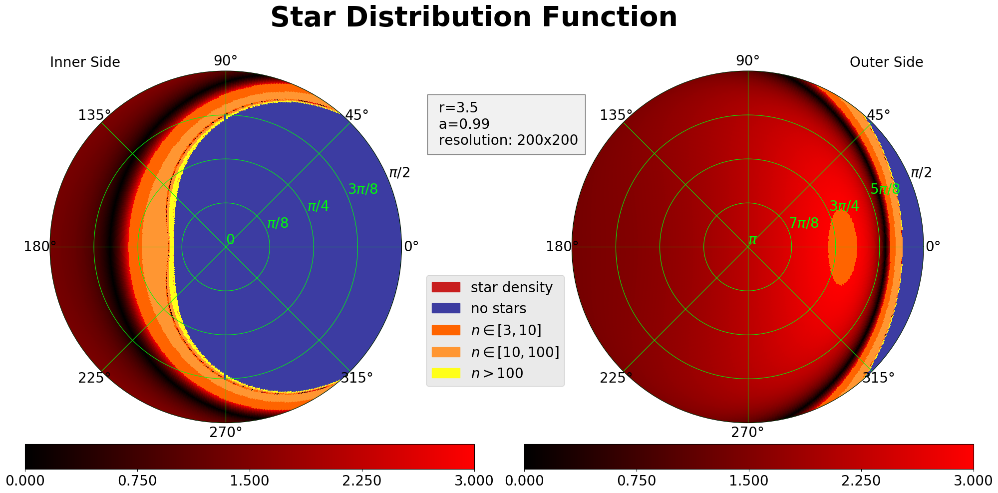
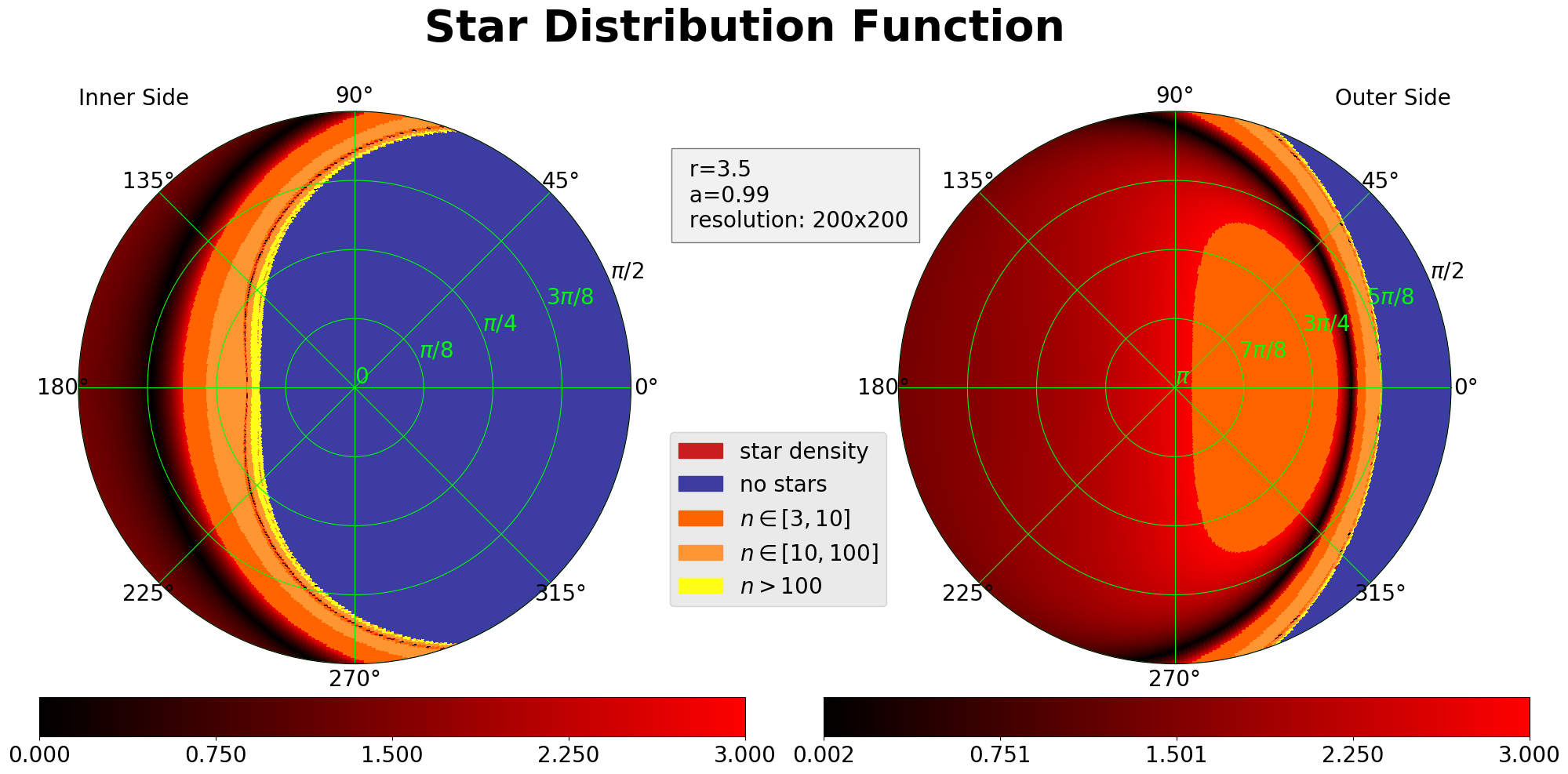
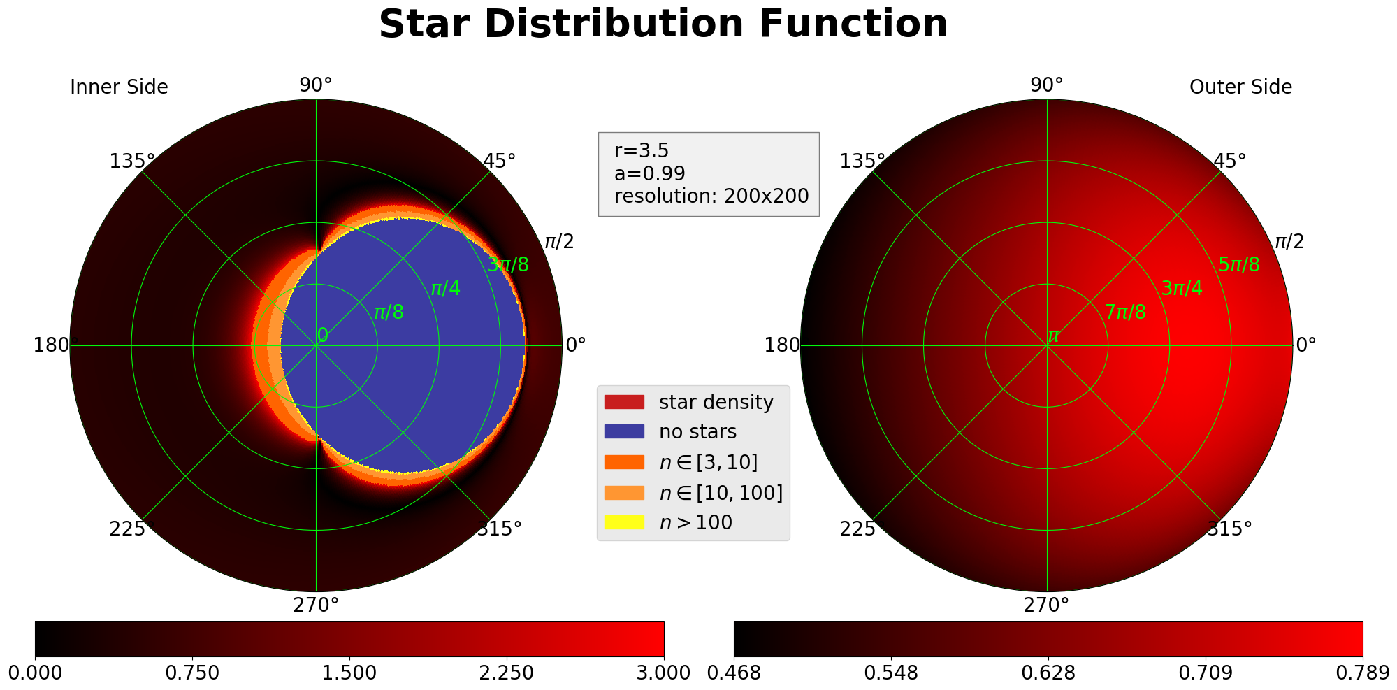
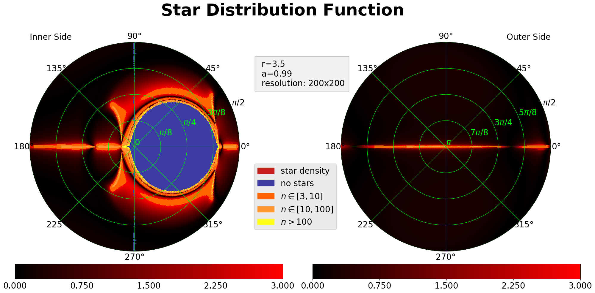
We have displayed the SDFs in figures consisting of two circles, which represent the “inner” and “outer” hemisphere oriented towards and away from the black hole respectively. The values of SDF were color-coded into a hybrid linear () and segmented () colormap, since SDF tends to diverge when approaching the BH’s shadow and the resulting large values in a small region around the shadow would mess up the color-coding of the rest of the picture on a purely linear colormap.
4.2 Initial conditions
Initial conditions for the reference ray
Consider an observer at an event orbiting in the equatorial plane of the Kerr black hole with the velocity with respect to the LNRF , and introduce two orthonormal bases along the observer’s worldline, the LNRF basis and the observer basis . The components of the 4-velocity of the observer as measured in the LNRF are given by the special relativistic formula , where is the Lorentz factor. Correspondingly, , which reflects the fact that the LNRF moves w.r.t. the observer with the velocity . The complete set of transformation relations is given by the boost formulae (perpendicular vectors do not change and the fourth vector is just a normalized combination of the original vectors orthogonal to the first one):
| (27) |
In the instantaneous physical 3-space of the observer , standard spherical coordinates are introduced using the correspondence (the zenith angle is measured from the radial direction pointing to the black hole and the azimuthal angle is measured from the vector in the clockwise direction w.r.t. , see figure 1).

In the observer’s frame, the wave 4-vector of the reference ray is initialized as , where is the unit vector in the direction in which the observer is looking (the photon is heading in the opposite direction, hence the extra minus sign) and is the index of refraction at the point where the observer is located. After initialization, we have to integrate towards negative values of the affine parameter (into the past).
Initial conditions for the beam
All rays of the beam are focused at the point at and spread into a circular beam, seen by the observer within the solid angle at . Focusing of the beam implies initial conditions (ICs) and spreading of the beam into the solid angle suggests with . The spatial part of the 4-vectors is supposed to be two independent vectors perpendicular to and to each other (in the sense of the induced 3-metric w.r.t. ), which have both the magnitude , therefore the radius of the circle as measured from is333 comes from our convention that the connecting vector points to an infinitesimally close point, . The radius of the circle enters ICs via , therefore . The time component of the vector is given by the condition (see (11)), and it vanishes, , for our choice of spatial ICs.
Initialization of differential equations
At the point , 10 dynamic variables entering the evolution equations must be initialized together with 3 required conserved quantities. Position of the central ray is initialized by the choice of the point somewhere in the equatorial plane (and above the event horizon), , . Vector is initially zero in the frame of the observer with our choice of ICs, therefore it is zero in any other frame too. The wave 4-vector, for both the reference ray and the adjacent ray, needs to be transformed from the observer’s frame to LNRF, which can be done by using inverse transformation to the transformation (27). To determine the conserving constants we must further pass from LNRF to the coordinate basis; for that purpose, use (B-10) and the fact that covector components transform like basis vectors. Finally, notice that thanks to our choice of ICs. Below we give the full list of ICs expressed in terms of the parameters , , and the two ellipse-generating vectors , which are unit 3-vectors perpendicular to (they can also be chosen to be perpendicular to each other, ):
| (28) |
where , and are defined in the appendix B. Note that the EoMs (B) are invariant w.r.t. the rescaling , , , , , . This means that we can freely choose the “typical scale” for and without the necessity to change the equations in any way. A good choice is and , since it removes the superfluous factors from the ICs.
4.3 Evaluation of SDF
Provided the plasma density gradient falls to zero sufficiently fast when , the reference ray 4-velocity at equals the wave 4-vector of radially incoming ray, . The cross-sectional area of the beam is therefore measured in the plane. Using the Thorne’s approach [7] we write the major and minor angular semiaxis of the ellipse as , where is the major and minor linear semiaxis of the ellipse. Since is in general not perpendicular to , it is more convenient (following [7]) to use the description in which the ellipse is encoded in the complex variable . It holds
and, consequently, (the major and minor semiaxis arises as the constructive and destructive sum of the phasors respectively). Also, if we notice that at infinity and , we find
where the subscript means that we have to replace all ’s with ’s in the definitions of the corresponding variables. The last step is evaluating . From the expression for it follows
and if we insert into the definition of SDF and denote , we obtain
| (29) |
4.4 Plasma distribution
In our calculations we have used various “toy models” of the plasma distribution, all of which can be found in the literature except for the last one which we have proposed ourselves. The advantage of these models is their smoothness, as well as the fact that the derivatives of the plasma density can be expressed analytically. The most trivial case is vacuum with . Another simple case is the distribution , when the ray equation coincides with the equation for a massive particle in vacuum. A model often used in the literature [13, 24] is the non-singular isothermal sphere (NSIS), defined as
| (30) |
where and are positive constants. The same model with is called the singular isothermal sphere [13, 24]. In Newtonian gravity, such sphere can be obtained as a solution for a static non-rotating self-gravitating gas cloud with the same temperature of the gas everywhere, supported against the collapse solely by the pressure gradient. Finally, as a disc-like distribution we have used a non-singular isothermal sphere modified by a function that flattens the distribution towards the equatorial plane,
| (31) |
where the parameter determines the magnitude of flattening.
5 General features of SDFs
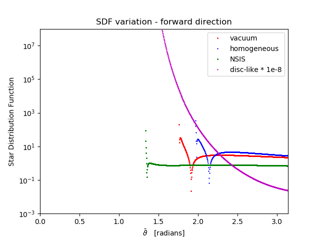
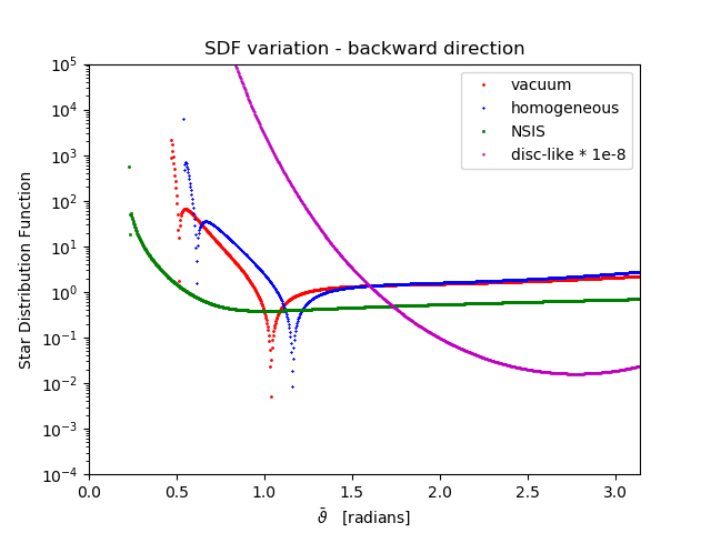
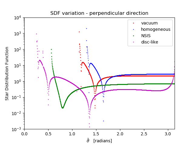
We have investigated four plasma distributions, namely no plasma, homogeneous plasma, NSIS (distribution (30)) and flattened NSIS (distribution (31)). The 4-velocity of the plasma was not important since it vanishes from the equations. We have chosen the locally non-rotating family of observers, since they filter out the special relativistic effects as much as possible and exist also near the event horizon (contrary to the static observers who become tachyonic inside ergosphere). In addition to that, we have limited ourselves to the observers located in the equatorial plane. The main properties of the SDFs obtained in this way are:
a) no plasma: it is well known that purely gravitational bending of light is achromatic (frequency independent), hence the SDF is independent of in the case with no plasma. Far from the black hole, the SDF is close to one in almost all directions, it changes rapidly only in the vicinity of the black hole shadow, decreasing to zero at Einstein’s ring and diverging at the edge of the shadow. The steep rise of the SDF near the shadow is caused by the multiple image generation by the BH. In fact, the SDF oscillates between zero and large values infinitely many times when approaching the shadow, but in the calculations presented here we do not see this behaviour due to low resolution. As we approach the BH, the behavior of the SDF stays qualitatively the same, but its features become more pronounced. Non-zero spin of the BH introduces asymmetry in SDF w.r.t. the azimuthal direction, with slightly greater values of SDF in the prograde direction. In particular, near the BH the outward-facing maximum of SDF is visibly shifted from in the prograde direction if the BH is rotating (see fig. 2). As the observer approaches the event horizon, the BH shadow becomes ever more pronounced, eventually encompassing the whole sky.
b) homogeneous plasma: in this case, the light rays behave as massive test particles in Kerr geometry. Recalling that , we see that plays the role of launching velocity and is, modulo factor , the launching Lorentz factor. If at least some rays are to reach infinity, the launching velocity must exceed the escape velocity, . Thus, the SDF acquires a new property: the night sky is not visible below . In case of rotating BH or a boosted frame, the escape energy exhibits non-trivial dependence on the launching direction. Finally, in the limit of large launching velocity, , we regain the vacuum picture.
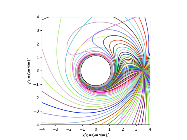
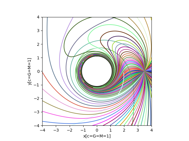
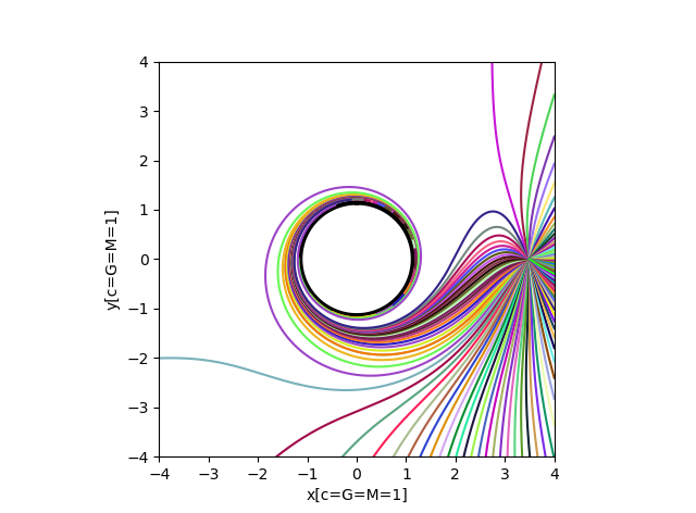
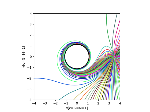
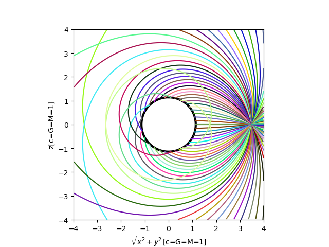
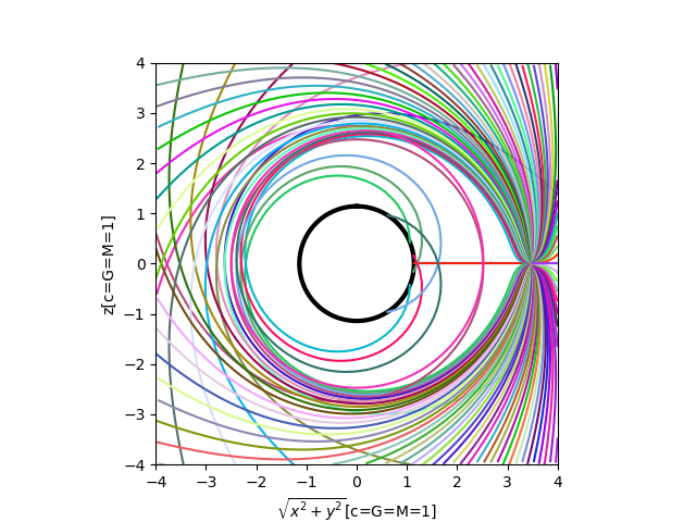
c) non-singular isothermal sphere: the -dependence of NSIS leads to radial acceleration, pushing the light rays away from the BH (see fig. 10 c)). This fights the gravitational pull of the black hole and may result in erasing the black hole shadow from the night sky entirely.
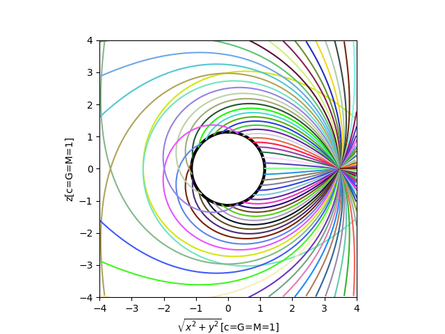
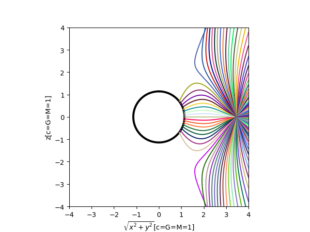
d) flattened NSIS: the disc-like shape of this distribution causes an additional deviation of the acceleration of rays from radial direction: the rays are pushed away from the equatorial plane (see fig. 10 d)). As a consequence, the number of rays the observer receives when looking in equatorial plane directions is hugely enhanced and SDF assumes large values in these directions, fading fast to nearly zero in most of the non-equatorial-plane directions. This model is complicated enough to cause that in the hemisphere facing the BH a quite complex pattern emerges as a result of the struggle between attraction from gravitation and repulsion from plasma (see fig. 5). In both NSIS distributions, the effects of plasma are negligible when just like in the constant distribution.
The influence of plasma on the shadow of BH was previously studied as well: analytic approach was cultivated in [19, 21], while numerical calculations were performed in [20]. Analytic approach was restricted to the specific class of plasma distributions, [19]. Numerical calculations, not subject to this constraint, produced the shape of the shadow with purely radial, power law and exponential distributions. Out of these works, our situation is most similar to [19], where the authors placed, like us, the observer at finite distance from the BH ( in their case). All papers also included description of the vacuum shadow, either directly or as a high frequency limit of the plasma shadow. Near-extremal BH vacuum shadow exhibits a typical feature – flattened left hand side of the shadow, which was present in all these papers and can be also seen in fig. 2; this feature is called “NHEKline” in some papers, e.g. in [21]. In homogeneous plasma, the increase in the size of the shadow with decreasing frequency was noticed in [19], and is also visible between figures 2 and 3. Paradoxically, distributions that decrease as we are getting further from the BH and vanish as approaches infinity have the opposite effect on the shadow: its size decreases with decreasing frequency. This feature can be observed in all three papers, as well as in figures 4 and 5. A more detailed discussion of this topic can be found in [19]. Finally, all figures, ours as well as those in the papers [19, 20, 21], suggest that plasma rounds off the BH shadow and suppresses its typical NHEKline signature at frequencies near .
Besides the plasma distribution, the form of SDF is influenced by other circumstances such as BH rotation, observer’s location and observer’s velocity. Rotation of black hole introduces asymmetry between prograde and retrograde direction at any spatial point outside the axis of rotation, and as a result, in case with no plasma the rays evolving forward (backward) in time are pulled in prograde (retrograde) direction. Thus, in our case the rays become more squashed together in prograde direction and we obtain greater SDF there (this is a naive opinion on the issue which seems to be confirmed by numerical calculation). An observer boosted by a significant fraction of speed of light in a certain direction sees the light rays pulled towards each other in that direction due to the special relativistic aberration of light, hence if the plasma is absent, SDF rises there. Also the BH shadow is pulled in that direction. These effects are modified in the presence of plasma. The situation gets more complicated, since the evolution of rays is now dependent on in addition to their direction. Therefore the set of rays used to calculate SDF for unboosted observer does not coincide with the set of rays used to calculate SDF for the boosted observer (this fact can be ignored in vacuum due to achromaticity of the light bending). Thus, there is no direct relation between SDF of two observers moving w.r.t. each other. Let us just note that at large distances from the BH, effects of gravitational pull are severely suppressed except for a narrow region around the BH shadow, while the optical effects of plasma may still be important depending on the plasma distribution. However, in the distributions primarily concentrated around the BH these effects are also suppressed everywhere except nearby the BH shadow. On the other hand, if the observer is very close to the BH, the gravitational pull dominates on a large portion of the night sky, leaving only a small part of the sky with well defined SDF that can be influenced by the presence of plasma. The influence is not easy to predict, the analysis being complicated by the fact that we do not have an analogue of Carter constant for a generic plasma distribution, only for distributions fulfilling the additional condition cited above, which was found in [19] and further discussed or applied in calculations in [6, 17, 18].
6 Conclusion
We have discussed some theoretical aspects of general relativistic geometrical optics in plasma, in particular, we have provided a simple derivation of RDE which was, to our knowledge, not presented in the literature before. We have also discussed conservation laws and normalization constraints, writing them in a covariant way. We have then introduced the concept of SDF and calculated numerically the SDFs in various cases. To do that, we have converted the EoMs for the reference ray, as well as the RDE, into a set of first order ODE. This allowed us to calculate the SDF point by point, in contrast to constructing a network of reference rays and computing the derivatives numerically, which would be certainly less exact, especially for rays that undergo several revolutions around the BH before escaping to infinity. The SDF was calculated for several different plasma distributions: the vacuum (no plasma), the homogeneous plasma, the NSIS and the flattened (disc-like) NSIS. We have discussed also the dependence of SDF on some other parameters, namely the distance of the observer from the BH, the observational frequency and the spin of the BH. In future work there are several directions which appear worth to follow. First, it would be interesting to calculate the damping effect of plasma on the light beam, the most dominant effect being probably the Thompson scattering. Second, we would like to look at the SDF of an observer outside the equatorial plane, which requires only slight modification of the initial conditions. Finally, it would be interesting to calculate the light curves of a distant star seen by a distant observer on the other side of the BH, when the incoming light is influenced simultaneously by the gravitational field of the BH and the refraction index of the surrounding plasma. Obviously, this is only interesting if the plasma itself is not shining significantly, so that it does not outshine the light from the distant star.
Acknowledgements
The work was supported by the grant VEGA 1/0985/16. M. S. is also thankful to the Comenius University for its support via the grants UK/159/2018 and UK/105/2017.
Appendix A Efficient variation procedure for the two-ray action
Consider the action (4) for a reference ray and a neighboring ray lying in the close vicinity of it. We can write , where is a positive parameter and is the connecting vector. Expand the action for the neighboring ray to the first order in ,
When rewriting the integral, we started from the equality 444The equality just states that the connecting vector is Lie-transported along the reference ray, . The same formula is used in the derivation of Jacobi equation. at , which holds because closes by definition a 4-sided polygon with , and we used its consequence, the equality , implied by vanishing of the torsion tensor. Demanding both and to obey the EoM for a ray suggests a variational principle for the second term on the r.h.s., with the boundary values of both and fixed. Thus, we can introduce the action for ray deviation:
| (A-1) |
The first term is the action for the equation of geodesic deviation a.k.a. Jacobi equation (similar term is proposed e.g. in [42, 43]), while the second term introduces plasma on the scene. Let us write the -variations as and the -variation as , where are vector fields vanishing at the boundaries. Since we need to go only to the first order in , we can discuss these variations separately. First consider the -variation. It holds
where we introduced the effective equality in which the terms with the total derivative (terms of the form ) are dropped. The variation yields yet again the evolution equation for the reference ray,
| (A-2) |
Now let us proceed to the variation w.r.t. . We will use the covariant variation rather than the standard one555The difference is that the covariant variation will also cause a change in , but this change is dependent on the -variation and will drop out eventually due to the ray equation.. Also, it is useful to realize that the commutation relations allow us to swap for and for . The geometric part of the Lagrangian varies as follows:
| (A-7) |
where is an auxiliary vector defined as . The Riemann curvature operator was introduced in order to rearrange the covariant derivatives, and in the course of calculation the identity , which follows from the symmetry of the Riemann tensor w.r.t. the interchange of the pairs of indices, was used. Let us now determine the -variation of the plasma term:
where . Collecting all terms we get:
where we have isolated the auxiliary term , which appears as a consequence of using the covariant variation and vanishes on the extremal due to the ray equation (A-2). Finally, using the definition of the covariant Hessian matrix we arrive at the ray deviation equation,
| (A-8) |
Appendix B Explicit formulae for RDE integration in Kerr geometry in LNRF
Equations of motion for adjacent ray in LNRF
Here we give the “totally unpacked version” of equations of motion:
The equations marked with the bullet are algebraic rather than differential and come from the conservation laws. The unknown symbols on the right hand sides encode Kerr geometry and plasma distribution and are defined in the following two paragraphs.
The complete set of equations comprises 10 differential and 4 algebraic equations which are to be solved twice for every reference ray (since the ellipse is generated by two vectors )666Alternatively, we can solve equations simultaneously, should it prove to be faster. In fact, this is how we proceeded.. There are also optional evolution equations for temporal and azimuthal coordinate, and , which may be added to the list to obtain the complete set of 16 equations of motion. Note, that Boyer-Lindquist coordinates are ill-defined on north/south pole. This can cause problems, if we try to integrate the system of rays with the reference ray crossing one of the poles (rays with ). The equations for reference ray cope with this problem by letting escape from the interval , but the equations for neighbouring ray blow up because of term , so it is generally good idea to avoid integrating these rays when calculating SDF. Rays closely passing the poles may also occasionally suffer from numerical problems, see e.g. blue spots on fig. 5 near values .
Kerr geometry
Kerr metric in the Boyer–Lindquist coordinates, in the notations adopted from Thorne et al. [7], is:
| (B-1) |
where , and
In this form an orthonormal covector basis arises naturally. The corresponding vector basis , carried by zero angular momentum observers, is called locally non-rotating reference frame (LNRF). The two bases are:
| (B-10) |
Connection forms (, where hatted indices refer to LNRF) are:
| (B-17) |
where and
| (B-26) |
We have used the abbreviations and . The formulae can be looked up in [44] or obtained directly by solving Cartan’s structure equations (to be found e.g. in [36]).
The LNRF curvature tensor , as computed in [44], is
| (B-33) |
where the pairs of indices and assume values , , , , and (in this order), and
| (B-36) |
The matrix is symmetric because of the symmetry of in the pairs of indices.
Plasma description
In our calculations we have restricted ourselves to stationary, axially symmetric plasma distributions, . Gradient of the function is , where and . The Hessian matrix can be easily calculated using the formula
The matrix is symmetric and has only 6 nonzero components:
| (B-43) |
Appendix C Numerical results
To illustrate the general features of the star distribution function discussed in the text, let us present here some example figures with our results.
a)
b)
c)
d)
a)
b)
c)
d)
References
- [1] R. P. Kerr, Phys. Rev. Lett. 11, 237 (1963)
- [2] J. M. Bardeen, in Black Holes – Les Astres Occlus, 215, eds. DeWitt C., DeWitt B. S., Gordon and Breach Science Publishers, Inc., New York (1973)
- [3] C. F. Paganini, B. Ruba, M. A. Oancea, arXiv: 1611.06927
- [4] E. Teo, Gen. Rel. Grav. 35, 1909 (2003)
- [5] P. V. P. Cunha, C. A. R. Herdeiro, E. Radu, H. F. Rúnarsson, Int. J. Mod. Phys. D 25, 1641021 (2016)
- [6] P. V. P. Cunha, C. A. R. Herdeiro, Gen. Rel. Grav. 50, 27 (2018)
- [7] O. James, E. Tunzelmann, P. Franklin, K. Thorne, Class. Quant. Grav. 32, 065001 (2015)
- [8] D. Kuchelmeister, T. Müller, M. Ament, G. Wunner, D. Weiskopf, Comput. Phys. Commun. 183, 2282 (2012)
- [9] J. Fukue, T. Yokoyama, Publ. Astron. Soc. Jap. 40, 15 (1988)
- [10] J.-P. Luminet, Astron. Astrophys. 75, 228 (1979)
- [11] S. U. Viergutz, Astron. Astrophys. 272, 355 (1993)
- [12] J. L. Synge, Relativity: The general theory, Amsterdam: North-Holland Pub. Co. (1960)
- [13] G. S. Bisnovatyi-Kogan, O. Y. Tsupko, MNRAS 404, 1790 (2010)
- [14] O. Y. Tsupko, G. S. Bisnovatyi-Kogan, Phys. Rev. D 87, 124009 (2013)
- [15] V. Perlick, O. Y. Tsupko, G. S. Bisnovatyi-Kogan, Phys. Rev. D 92, 104031 (2015)
- [16] G. S. Bisnovatyi-Kogan, O. Y. Tsupko, Plasma Phys. Rep. 41, 562 (2015)
- [17] G. S. Bisnovatyi-Kogan, O. Y. Tsupko, Universe 3, 57 (2017)
- [18] T. Kimpson, K. Wu, S. Zane, MNRAS 484, 2411 (2019)
- [19] V. Perlick, O. Y. Tsupko, Phys. Rev. D 95, 104003 (2017)
- [20] Y. Huang, Y.-P. Dong, D.-J. Liu, Int. J. Mod. Phys. D 27, 1850114 (2018)
- [21] H. Yan, Phys. Rev. D 99, 084050 (2019)
- [22] G. S. Bisnovatyi-Kogan, O. Y. Tsupko, Grav. Cosm. 15, 20 (2009)
- [23] H. Chakrabarty, A. B. Abdikamalov, A. A. Abdujabbarov, C. Bambi, Phys. Rev. D 98, 024022 (2018)
- [24] C. A. Benavides-Gallego, A. A. Abdujabbarov, C. Bambi, Eur. Phys. J. C 78, 18 (2018)
- [25] A. Rogers, MNRAS 451, 17 (2015)
- [26] M. A. Abramowicz, P. C. Fragile, Liv. Rev. Rel. 16, 1 (2013)
- [27] N. I. Shakura, R. A. Sunyaev, Astron. Astrophys. 24, 337 (1973)
- [28] I. D. Novikov, K. S. Thorne, in Black Holes – Les Astres Occlus, 343-451, eds. DeWitt C., DeWitt B. S., Gordon and Breach Science Publishers, Inc., New York (1973)
- [29] D. N. Page, K. S. Thorne, Astroph. J. 191, 499 (1974)
- [30] R. F. Penna, A. Sadowski, J. C. McKinney, MNRAS 420, 684 (2012)
- [31] R. Narayan, R. Mahadevan, E. Quataert, in Theory of Black Hole Accretion Disks, eds. M. A. Abramowicz, G. Bjornsson, and J. E. Pringle, CUP, Cambridge (1998)
- [32] B. Paczynski, Acta Astron. 48, 667 (1998)
- [33] D. Pugliese, G. Montani, M. G. Bernardini, MNRAS 428, 952 (2013)
- [34] S. Pineault, R. C. Roeder, Astroph. J. 212, 541 (1977)
- [35] S. Pineault, R. C. Roeder, Astroph. J. 213, 548 (1977)
- [36] M. Fecko, Differential Geometry and Lie Groups for Physicists, CUP, Cambridge (2006)
- [37] R. P. Feynman, R. B. Leighton, M. L. Sands, The Feynman Lectures on Physics, Addison-Wesley, Boston (2006)
- [38] R. Kulsrud, A. Loeb, Phys. Rev. D 87, 2 (1992)
- [39] K. Schulze-Koops, V. Perlick, D. J. Schwarz, Class. Quant. Grav. 34, 215006 (2017)
- [40] C. W. Misner, K. S. Thorne, J. A. Wheeler, Gravitation, W. H. Freeman, San Francisco (1973)
- [41] https://docs.scipy.org/doc/scipy/reference/generated/scipy.integrate.ode.html
- [42] S. L. Bażański, J. Math. Phys. 30, 1018 (1989)
- [43] S. L. Bażański, Ann. I. H. Poinc. A 27, 145 (1977)
- [44] J. M. Bardeen, W. H. Press, S. A. Teukolsky, Astroph. J. 178, 347 (1972)