AMS-100: The Next Generation Magnetic Spectrometer in Space – An International Science Platform for Physics and Astrophysics at Lagrange Point 2
Abstract
The next generation magnetic spectrometer in space, AMS-100, is designed to have a geometrical acceptance of and to be operated for at least ten years at the Sun-Earth Lagrange Point 2. Compared to existing experiments, it will improve the sensitivity for the observation of new phenomena in cosmic rays, and in particular in cosmic antimatter, by at least a factor of 1000. The magnet design is based on high temperature superconductor tapes, which allow the construction of a thin solenoid with a homogeneous magnetic field of inside. The inner volume is instrumented with a silicon tracker reaching a maximum detectable rigidity of and a calorimeter system that is 70 radiation lengths deep, equivalent to four nuclear interaction lengths, which extends the energy reach for cosmic-ray nuclei up to the PeV scale, i.e. beyond the cosmic-ray knee. Covering most of the sky continuously, AMS-100 will detect high-energy gamma rays in the calorimeter system and by pair conversion in the thin solenoid, reconstructed with excellent angular resolution in the silicon tracker.
keywords:
cosmic rays, dark matter, antimatter, cosmic-ray knee, high-energy gamma rays, multi-messenger astrophysics1 Introduction
A Magnetic Spectrometer with a geometrical acceptance of 100 , AMS-100, is a major new space mission which addresses a number of key science questions in multi-messenger astrophysics, cosmic-ray physics and particle physics (Fig. 1). Several of these questions have emerged in the last decade, as a result of the tremendous success of recent space missions, such as PAMELA [1], Fermi-LAT [2], AMS-02 [3], CALET [4], and DAMPE [5]. In particular, the magnetic spectrometer AMS-02 has revealed several unexpected new features in the cosmic-ray matter [6, 7] and antimatter fluxes [8, 9] that have challenged much of our traditional understanding of particle astrophysics, across a range of topics such as the nature of dark matter and the origin and propagation of cosmic rays. Direct measurements of cosmic rays provide important constraints to trace the structure of the Galaxy, and to search for signatures of new physics [10, 11, 12]. Even more important could be the observation of candidate events in cosmic rays [13], which could have profound implications for understanding the origin of the matter-antimatter asymmetry of the universe.
These questions cannot be addressed by calorimeter-based instruments in space, which, in the absence of magnetic deflection, can measure neither the charge sign nor the mass of the incoming particles. Therefore we believe that ground-breaking progress for fundamental physics requires a next generation magnetic spectrometer in space. Due to the strong dependence of the cosmic-ray flux on energy , approximated by , every increase in energy reach by a factor of 10 requires an increase in geometrical acceptance by a factor of 1000.
Simply scaling the dimensions for the telescope-like geometries of PAMELA or AMS-02 would not allow significantly enhancing the geometrical acceptance and the energy reach at the same time. Increasing the height would enhance the energy reach but reduce the acceptance. Increasing the diameter would enhance the acceptance but reduce the magnetic field for a fixed magnet wall thickness and hence the energy reach. This dilemma can only be overcome by moving to a different detector geometry. A possible solution has been pioneered successfully by the BESS experiment [14] with a thin solenoid. The key here is the fact that the central magnetic field for a long solenoid only depends on the number of turns, the current and the length, but not on the radius. Therefore, for a solenoid of given wall thickness and instrumented with a tracking detector on the inside like a classical collider experiment, both the geometrical acceptance and the maximum detectable rigidity (MDR, defined by , where is the uncertainty of the rigidity measurement) increase quadratically with the radius if the diameter-to-length ratio stays constant. If placed far away from Earth, such an instrument has an angular acceptance of up to steradian due to its rotational symmetry, superior to any telescope-like geometry.
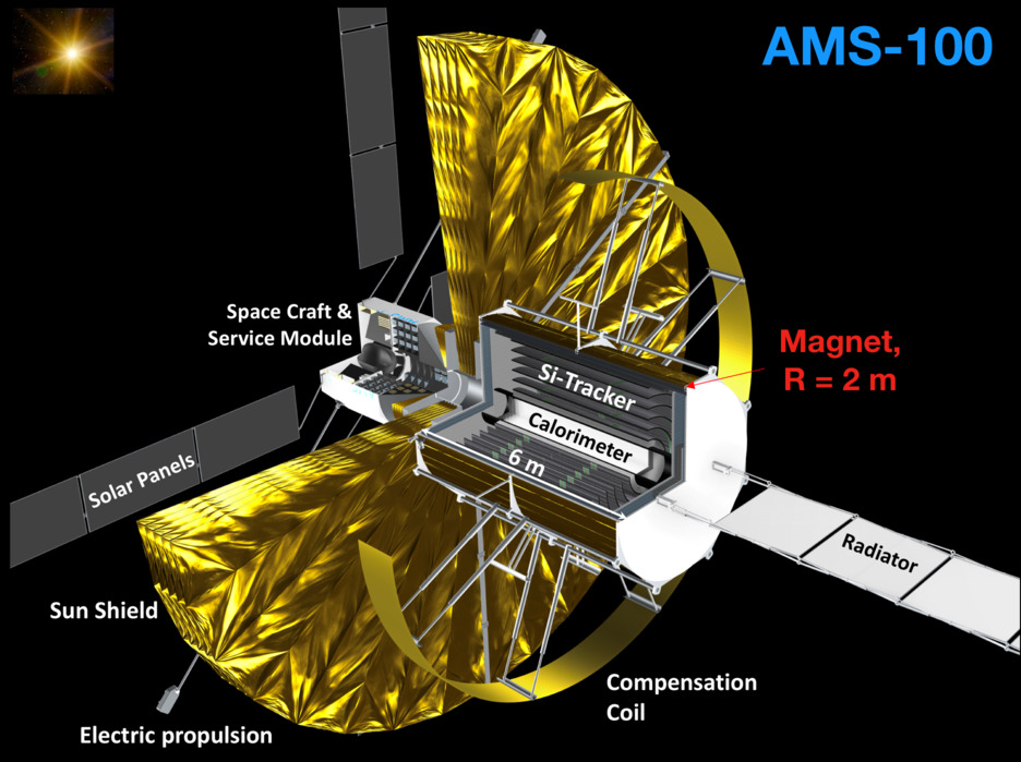
The instrument described in this article will explore uncharted territory in precision cosmic-ray physics by employing a suite of sophisticated detector systems designed to improve on existing instrumentation in both precision and in energy reach. The key element of the instrument is a thin, large-volume high temperature superconducting (HTS) solenoid magnet which creates a homogeneous magnetic field of in the tracking volume. It is cooled passively to . An expandable compensation coil balances the magnetic moment of the solenoid and allows the attitude control of the instrument within the heliospheric magnetic field. Combining this powerful solenoid with proven tracking technologies and innovative “cubic” calorimetry designs, the spectrometer will achieve an MDR of , with an effective acceptance of . The central calorimeter has a depth of 70 radiation lengths (), or 4 nuclear interaction lengths (). This instrumentation will allow probing, with high statistical power and high precision, the positron and electron spectra to , the antiproton spectrum to , and the nuclear cosmic-ray component to , past the cosmic-ray knee.
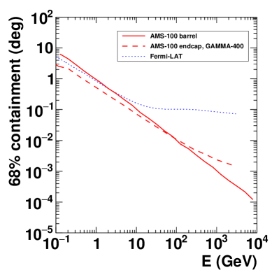
For the first time, this instrument will have the acceptance and resolution to probe the cosmic-ray antideuteron spectrum with high precision. AMS-100 will vastly expand our sensitivity to heavy cosmic antimatter (). Covering most of the sky continuously, AMS-100 will provide high-resolution survey measurements of rays to energies beyond the TeV scale, with an angular resolution of at and at , comparable to X-ray telescopes [15].
The instrument will be installed on a spacecraft and operated for at least ten years at the Sun-Earth Lagrange Point 2 (L2). This positioning is necessary to create a stable cold environment for the operation of the HTS magnet. In a low-Earth orbit, the interaction of the residual magnetic moment with the geomagnetic field would result in a complete loss of attitude control. In addition, the shadow of the Earth would reduce the field of view and the geomagnetic cutoff would limit the sensitivity to low-energy cosmic antimatter, in particular to antideuterons from dark matter annihilations.
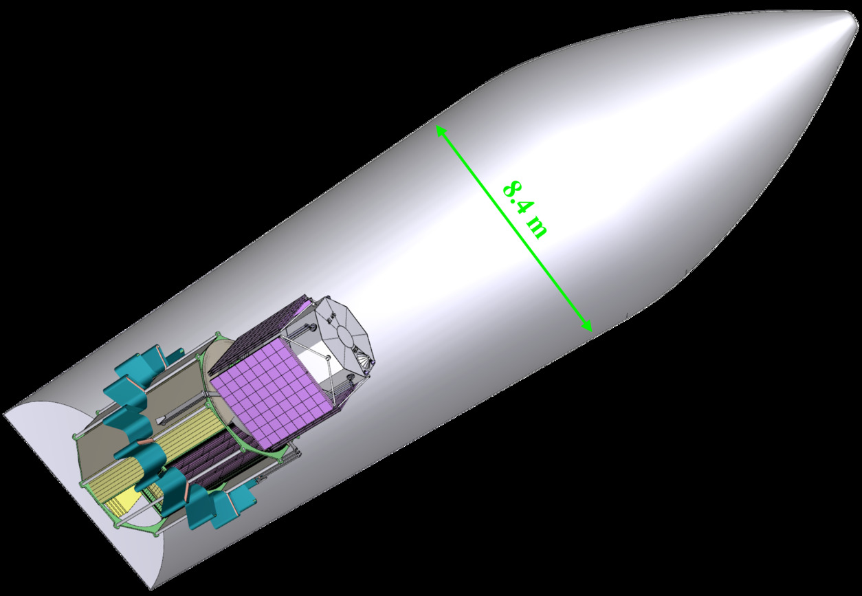
To fulfill the science requirements, the full payload has a mass of and hence requires new heavy-lift launch capabilities such as NASA’s Space Launch System (SLS) or China’s Long March 9 rocket, which are under development for human missions to Mars. Figure 2 illustrates the launch configuration in an SLS fairing.
A plausible timeline for instrument definition, design, development, and testing would target a launch date in 2039, though this requires an early commitment from the agencies and the community to perform the necessary R&D tasks. This will include some level of underlying technology development, as well as a pathfinder mission to test the high temperature superconducting solenoid magnet system at L2.
The purpose of this article is a description of the general detector concept. Several publications will follow describing the magnet system, the event trigger and DAQ system, the structural and thermal concept, the service module, the individual sub-detector systems, the pathfinder mission, and the physics program in detail.
2 AMS-100 Magnet System
The geometrical acceptance of defines the dimensions of the thin main solenoid. It has a length of and a diameter of (Fig. 1) and creates a central magnetic field of along the -axis. As the magnet will be operated at , the only option is to construct it from second-generation rare-earth barium copper oxide (REBCO) high temperature superconducting tapes [16, 17]. These HTS tapes have a typical thickness of and can carry high current densities even at field strengths of [18] and tolerate severe mechanical stresses [19, 20] thanks to a thick Hastelloy substrate. Today, REBCO tapes are available in high lengths [21], and are studied in several research projects. A typically thick copper stabilizer completes the HTS tapes (for more details, see for example Refs. [22, 23, 24]) which can be easily soldered for joints. It has been shown in Ref. [25] that increasing the stabilizer thickness aids in reducing the magnet temperature at a quench. For the AMS-100 magnets, we assume that the copper stabilizer will be replaced by an equivalent aluminum stabilizer to minimize the material budget [26].
Quench protection and understanding the dynamics of the quench process in HTS tapes [27] are the key for the long term stable operation of such a magnet in space. As one possible option, HTS coils can be protected from an irreversible quench by winding them from tapes without additional insulation [28, 29, 30], thus allowing the current to flow in the radial direction in case of a thermal runaway.
Generally REBCO tapes are available in piece lengths of with joint resistances of less than [31]. For a long REBCO tape at and a magnetic field of , a critical current of , equivalent to for wide tape, has been reported in 2019 [21].
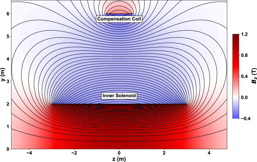
The key parameters of the magnet system for AMS-100 are given in Table 1. Progress on the critical current for REBCO tapes, as expected in the coming years, will proportionally reduce the number of layers required to obtain a central magnetic field of and will hence allow reducing the weight and the material budget of the coils further. The magnetic field is visualized in Fig. 3.
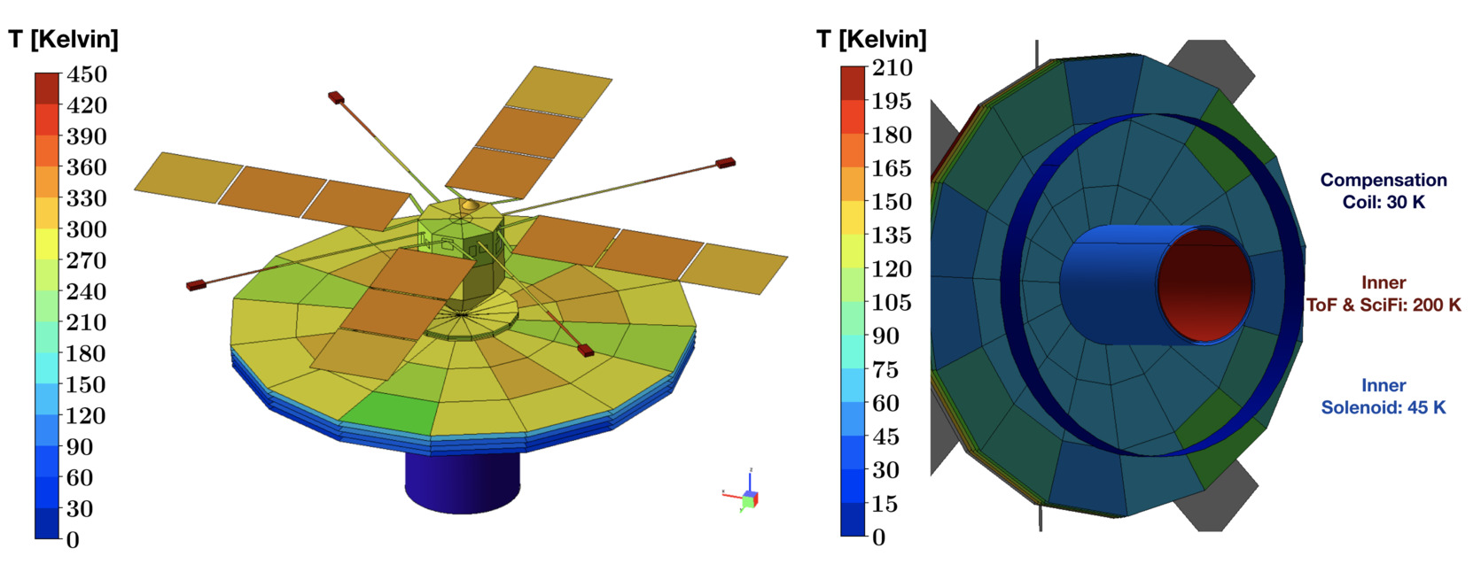
The thin solenoid is cooled by radiation to deep space and operated in thermal equilibrium at a temperature of behind a sunshield. A simplified thermal model taking only radiation into account is shown in Fig. 4. The main solenoid is insulated thermally from the other detector components by multi-layer insulation. The obtained magnet temperatures leave some margin for conductive thermal loads which have to be taken into account in the final thermo-mechanical design. Similar to all other detectors inside the main solenoid, the silicon tracker temperature will be kept constant at using a two-phase cooling system or heat pipes connected to the radiator opposite the sunshield (Fig. 1). This temperature of might have to be adjusted within the overall thermo-mechanical model to ensure a stable operating temperature for the main solenoid of . All sub-detector systems are designed to have a better signal-to-noise ratio at such low temperatures than at room temperature and first laboratory tests of various detector components down to liquid nitrogen temperatures have already been performed successfully at RWTH Aachen [32].
| Main | Compensation | |
|---|---|---|
| solenoid | coil | |
| Inner radius | ||
| Length | ||
| Current | ||
| Temperature | K | K |
| HTS tape width | ||
| HTS tape layers | 22 | 4 |
| at center | ||
| Stored energy | ||
| Magnetic moment | ||
| Coil thickness | ||
| Mass | ||
| Volume | ||
| Material budget | ||
| Wire length | ||
| Hoop stress | ||
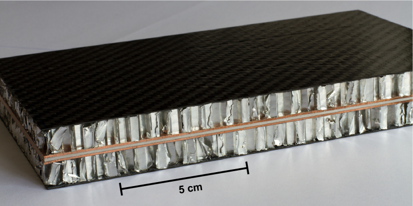
Particularly for the sensitivity to antimatter in cosmic rays, the small wall thickness of the main solenoid and its support structure are of key importance. One option for this that we have studied in more detail consists of two lightweight aluminum honeycomb structures with a height of each that sandwich the magnet and have carbon fiber face sheets on the outside (Fig. 5). The coil would be assembled on a temporary support and afterwards the outer honeycomb and carbon fiber face sheets would be laminated directly onto the outer side of the magnet. In the next step, the temporary inner support would be removed and the inner honeycomb and carbon fiber face sheets would be laminated. The total material budget of this structure would be equivalent to a solid aluminum cylinder of thickness (). The further optimisation of this lightweight magnet support structure will have to take all components of the instrument and the constraints from the thermal model into account.
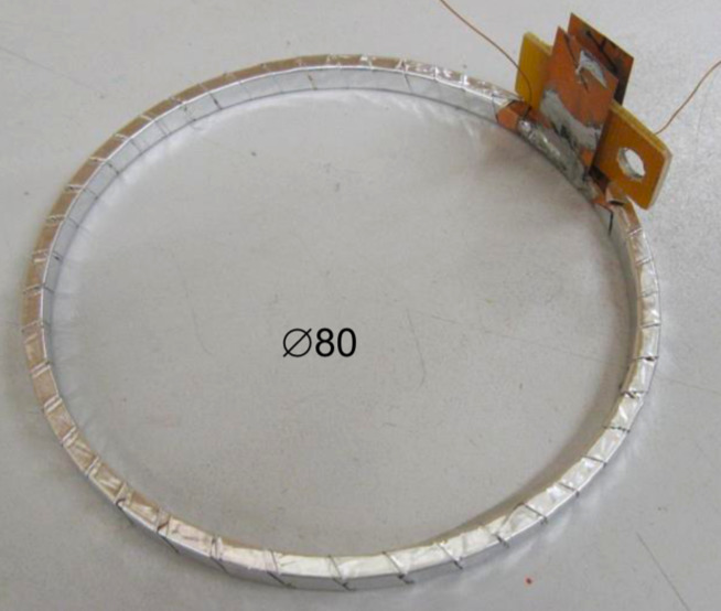
It has never been demonstrated that a HTS magnet with a lightweight support structure can be operated in space. In particular, the vibrations during the rocket launch are a concern. We have therefore started to produce first prototypes (Fig. 6) of thin HTS pancakes to performe space qualification tests including vibration and thermo-vacuum tests.
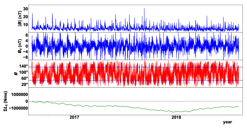
For the operation of a large solenoid in deep space, the interaction with the interplanetary magnetic field (IMF) is a major concern. The IMF has a complicated time-dependent structure. Due to the rotation of the Sun (period of ), its magnetic field winds up into a large rotating spiral. The heliospheric magnetic field changes polarity every 11 years [34]. It is distorted at the orbit of AMS-100 around L2 by the geomagnetic field and by solar flares. Due to the solar wind, the magnetic field at L2 still has an average strength of , varying between 0 and . In combination with the large magnetic moment of the AMS-100 main solenoid, this causes an average torque of . Based on measurements of the heliospheric magnetic field at Lagrange Point 1, which is very close to L2 on heliospheric scales, we can derive the expected angular momentum as a function of time (Fig. 7). Even though the magnetic field reverses polarity periodically, the accumulated angular momentum reaches a value on the order of over the course of one year. Such a large angular momentum cannot be balanced by reaction wheels or control moment gyroscopes. Instead, a compensation coil is needed with opposite field direction to balance the magnetic dipole moment of the main solenoid (Fig. 3).
With a diameter of , the compensation coil has to be an expandable coil, as has been studied for radiation shielding in space in [36]. It will consist of of HTS tape embedded and reinforced by thick kevlar or zylon layers. The support structure of this coil is designed to avoid small bending radii for the HTS tape. The Lorentz force will push the compensation coil outwards when the coil is powered. This movement will be supported by expanding booms. In the expanded state, the compensation coil is in stable mechanical equilibrium (Fig. 3). The very small additional material budget of the compensation coil will have negligible impact on the detector performance. Compensating the magnetic dipole moment of the main solenoid requires a regulation of the current in both magnets at the ppm level, similar to the precision achieved for the current regulation of the LHC quadrupole magnets [37].
3 AMS-100 Detector
3.1 Overview
The AMS-100 detector (Fig. 8) is located on the cold side behind the sunshield.
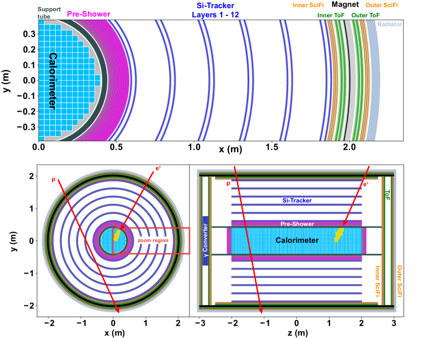
The main solenoid is instrumented both on the outside and on the inside with a 3-layer high-resolution scintillating fiber (SciFi) tracker [38, 39] and a 2-layer time of flight system (ToF). The SciFi tracker is assumed to have a single point resolution of . These sub-detectors will provide fast information on the incoming particles, as undistorted by the instrument as possible.
The inner detector consists of a silicon tracker, similar in design to the AMS-02 silicon tracker [40], followed by a pre-shower detector and a Lutetium-Yttrium oxyorthosilicate (LYSO) crystal calorimeter [41] with an outer radius of . In addition to the SciFi-Tracker modules and ToF-detectors, the endcap opposite the service module is instrumented with photon converters to allow the reconstruction of low-energy photons with good angular resolution. These converters consist of silicon detector layers interleaved with thin tungsten layers as proposed for GAMMA-400 [42].
AMS-100 has a geometrical acceptance of , i.e. 1000 times the acceptance of AMS-02. The instrument will monitor most of the sky continuously and will orbit around the Sun in one year, together with Earth and L2. This will guarantee homogenous sky coverage for -ray astronomy. The weight estimate of the instrument is given in Table 2. It has eight million readout channels in total and an estimated total power consumption of .
| Component | Weight (t) |
|---|---|
| Tracking and ToF | 5 |
| Calorimeter | 12 |
| Main solenoid | 1 |
| Cabling | 3 |
| Cooling | 3 |
| Service module | 2 |
| Radiators | 1 |
| Sunshield | 1 |
| Support | 9 |
| Contingency | 6 |
| Total | 43 |
3.2 Event trigger
Reducing the rate of incoming particles to an acceptable level of a few kHz for the higher level DAQ systems and to a data rate of [43] for the transfer to Earth with on-board computers will be a major challenge. To overcome it, the fast information provided by the outer detector (ToF-system and SciFi-tracker) will be used for the trigger decisions, in combination with calorimeter measurements: The track segments of the higher energy particles reconstructed in the SciFi tracker will provide a first estimate of the particle’s rigidity up to the TV scale, and the ToF signal amplitudes will determine the particle’s charge. This will allow the configuration of flexible trigger menus. For example, light nuclei with rigidity below have to be mostly rejected. Charged particles with an energy below will be deflected by the magnetic field of the main solenoid and will not be able to enter the detector volume. Prescaled random triggers will be used to estimate the related trigger efficiencies. In addition, those SciFi- and ToF-layers located outside the main solenoid will be used to veto charged particles when reconstructing rays.
3.3 Silicon tracker
The silicon tracker is assumed to have a single point resolution of in the bending plane for particles. It consists of six double layers arranged in cylindrical geometry (Fig. 8) leading to a maximum of 24 measurement points for a single track. For comparison, the CMS barrel silicon tracker [44] has an outer radius of and consists of 10 layers, providing up to 20 measured points for a cosmic muon going through the instrument. In combination with the diameter of the magnet and the magnetic field of , the AMS-100 silicon tracker provides an MDR of .
3.4 Time-of-Flight system
To reconstruct particle masses and thus identify isotopes in cosmic rays, a high-resolution ToF-system is required. Such systems constructed from small scintillator rods with time resolution of are presently under construction [45, 46]. We assume here that the time resolution of the PANDA ToF can be significantly improved using a larger coverage of the scintillator rods with SiPMs and operating the detector at . For particles, we target for a time resolution of for a single scintillator rod leading to a time resolution of for the 4-layer ToF system.
3.5 Calorimetry
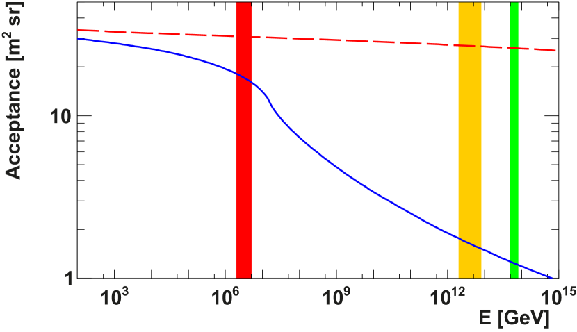
The pre-shower detector and the LYSO crystal calorimeter are used to separate electromagnetic and hadronic showers, and to measure the energy of electrons, positrons and photons, as well as protons and ions beyond the MDR. The crystal calorimeter is inspired by the design of the HERD detector [41] and allows the three-dimensional reconstruction of the shower shape. The pre-shower detector consists of 12 silicon detector layers interleaved with thin tungsten layers to provide good angular resolution for the measurement of rays and to limit the backsplash of the calorimeter into the silicon tracker. This combination of pre-shower detector and crystal calorimeter has a depth of , or , for particles incident in the bending plane of the main solenoid and hitting the calorimeter centrally. The geometrical acceptance of this system allows the measurement of cosmic nuclei with energies above up to the cosmic-ray knee at the PeV scale (Fig. 9). With today’s accelerators, AMS-100 can only be calibrated up to . In orbit, the energy scale of the calorimeter system will be calibrated in the energy range from to using the rigidity measurement of charged cosmic rays in the spectrometer.
3.6 Support tube and service module
The main structural element is a central thick carbon support tube with an outer radius of around the calorimeter. It will mechanically stabilize the detector during the launch and connect the service module to the launch adapter, which is the interface to the rocket. The main solenoid and the other subdetectors are connected to the central support tube by lightweight carbon fiber structures. Services are routed in the volumes between the barrel and the endcap detectors to the service module. The service module accommodates the DAQ system, the power distribution system, the telecommunication system, the attitude control, the thermal control system, and an electric propulsion system to keep a stable orbit around L2. A combination of reaction wheels and electric propulsion is used to keep the orientation of the sunshield stable with respect to the Sun.
3.7 Sunshield
The sunshield has a radius of and is designed similar to the concept developed for the James Webb Space Telescope [43]. The dimensions of the sunshield are chosen such that a pointing accuracy of a few degrees towards the Sun is sufficient to keep the magnet system cool. Other than for thermal reasons, the orientation of the instrument has no impact on the physics program. Star trackers will be used to monitor the orientation to provide precision information for the -ray astronomy program.
4 AMS-100 Physics Program
This paragraph can only cover first ideas related to the AMS-100 physics program, a lot of new aspects have to be worked out in more detail. This includes the sensitivity to various isotopes in cosmic rays, heavy nuclei beyond iron in cosmic rays, strangelets [47], magnetic monopoles [48], particles with fractional charges [49], evaporating primordial black holes [50, 51], search for signatures of dark matter annihilation or decay in -ray lines [52, 53], search for axions [54, 55], or tests of quantum gravity by precisely measuring the energy and arrival time of photons from -ray bursts [56], to mention a few examples that can be covered in principle with unprecedented sensitivity by such a powerful instrument.
For the following performance estimates, the detector acceptances have been determined with the help of a Geant4 [57] simulation.
4.1 Protons and heavier nuclei
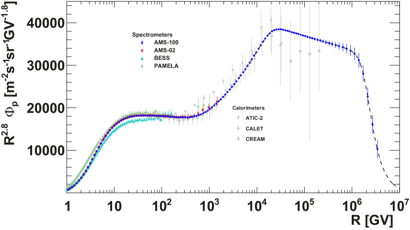
Protons are the most abundant species in cosmic rays. PAMELA and AMS-02 have reported a spectral break above in protons and other light nuclei [58, 59, 60]. Spectral breaks encode information about the sources and the propagation of cosmic rays [61, 62]. Up to now there is no coherent description of the various features observed in the energy spectra of cosmic rays. AMS-100 will measure protons and heavier nuclei in cosmic rays up to the maximum energy that can be reached by galactic cosmic-ray accelerators (Fig. 10). The positions of the spectral features in the spectra of different species, as well as the dependence of their appearance on the nucleus charge should provide the most detailed information about the cosmic-ray sources and processes in the interstellar medium. This information forms the necessary basis for other studies detailed below, such as the origin of cosmic-ray positrons, electrons, antiprotons, and antimatter. In addition, these direct measurements at the highest energies will allow us to investigate the change of the chemical composition of cosmic rays at the knee and gather invaluable information about the transition from Galactic to extragalactic cosmic rays.
4.2 Positrons and Electrons
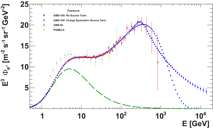
The observed excess of high-energy positrons above the expected yield from cosmic-ray collisions has generated widespread interest and discussions. Possible interpretations range from new effects in the acceleration and propagation of cosmic rays [68, 69, 70] to acceleration of positrons to high energies in astrophysical objects [71, 72, 73, 74, 75, 76, 77, 78, 79] and to dark matter [80, 81, 82, 83, 84, 85, 86, 87, 88] as a new source of cosmic-ray positrons. The latest data on the positron flux from AMS-02 show a spectral break at followed by a sharp drop [9]. The detailed understanding of the shape of the spectrum above this energy is the key to deduce the origin of these high energy positrons.
A generic source term, that describes the contribution of the new source responsible for the positron excess, is given by a power law with an exponential cutoff (e.g., Ref. [9]). AMS-100 will be able to precisely measure the cosmic-ray positron spectrum up to (Fig. 11).
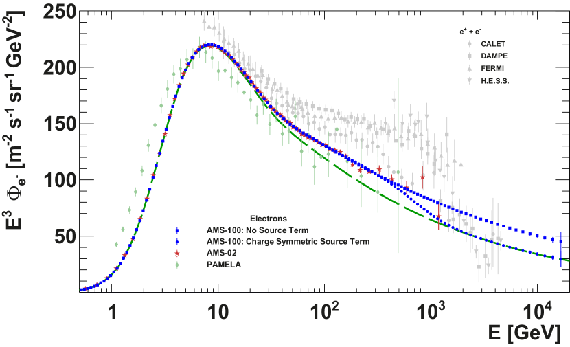
If the origin of the source term is a process producing electrons and positrons in equal amounts, the effect should also be detectable in the cosmic-ray electron spectrum. Both pulsar models and dark matter models generically predict such a charge-symmetric source term. H.E.S.S. [90] and DAMPE [91] have observed a spectral break of the combined electron and positron flux at about followed by a sharp drop, which might be related to this question. AMS-100 will be able to precisely measure the cosmic-ray electron spectrum up to (Fig. 12) and detect features associated with the local sources of electrons predicted in propagation models. Identifying such features will shed light on the origin of positrons, electrons, and other cosmic-ray species.
4.3 Antiprotons
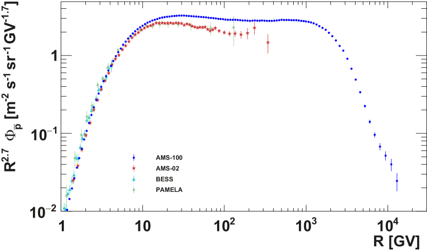
Positrons and electrons could be generated by a pulsar, but not antiprotons. Antiprotons can only be produced in high-energy interactions or in the annihilation of dark matter particles. Therefore, antiproton measurements may provide support to the dark matter hypothesis for the origin of the positron excess or rule it out. Independently, they provide another crucial probe of the processes in the interstellar medium, as well as production and acceleration of secondary species in the sources [96]. AMS-100 will be able to measure the antiproton spectrum up to the energy scale and provide precise information on the spectral shape. Hence it will shed light on many questions associated with the origin of cosmic rays and with the nature of dark matter (Fig. 13).
4.4 Antihelium
AMS-02 has shown both and candidate events at conferences [13]. These unexpected events are observed in AMS-02 at a rate of 1 event/year or 1 event in 100 million He events. The rate of secondary nuclei predicted by coalescence models is significantly lower. Therefore, the origin of the nuclei is unclear. The independent confirmation of these candidate events would have the most profound implications for physics and astrophysics. Besides the question of the statistical significance of the signal, the independent systematic uncertainties of the new instrument are essential. This requires an instrument with a different detector design at a different location in space. Extrapolating the AMS-02 event rate to the AMS-100 acceptance results in the prediction of finding in the order of 1000 events/year. The precision measurement of the spectral shape of the flux would allow tests of the origin of . The rotational symmetry of AMS-100 allows detailed systematic cross-checks of such a result equivalent to inverting the magnetic field.
4.5 Antideuterons
| Experiment | Energy range | sensitivity | Ref. |
|---|---|---|---|
| () | () | ||
| GAPS | to | [99] | |
| AMS-02 | to | [100] | |
| to | [100] | ||
| AMS-100 | to |
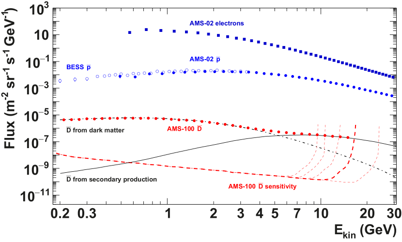
Antideuterons potentially are the most sensitive probe for dark matter in cosmic rays [101, 102]. While antiprotons are predominantly produced in secondary interactions in the interstellar medium, antideuterons at low energy have no other known origin. No antideuterons have ever been identified in cosmic rays. The current best limit has been set by BESS [103], excluding a flux of between and at the confidence level. The expected sensitivity of AMS-100 is in the energy range between and . It is compared to other experiments in Table 3. At this level of sensitivity, it is no longer useful to quote an integral sensitivity, which is related to the chances of observing a certain number of events anywhere inside a given energy range. Instead, we calculate a differential sensitivity, which can be directly compared to model predictions for the differential flux. We choose a logarithmic energy binning with 20 bins per decade and calculate the sensitivity individually for each bin. It is defined as the confidence level limit that will be set in case no events are observed in the given bin. The differential sensitivity for antideuterons is shown in Fig. 14. AMS-100 will be the first instrument to measure the cosmic-ray antideuteron spectrum with thousands of events, even in the case that antideuterons originate only from secondary production. AMS-100 will have the sensitivity to distinguish between antideuterons originating in dark matter annihilations and those produced in interactions within the interstellar medium, due to the different spectral shapes expected for these components. While it is not clear if antideuterons from dark matter annihilation exist, the observation of antideuterons from secondary production would allow us to set additional constraints on the and rates in cosmic rays: Within the coalescence model [104], every nucleon in the antimatter particle reduces the production rate by a factor depending on the energy, i.e. we expect in cosmic rays if there is no new source for one of these antimatter species. A simultaneous measurement of these sensitive probes for new physics is therefore required to derive a coherent picture.
4.6 High-energy Gamma Rays
Building on the success of current-generation -ray detectors such as Fermi-LAT [108], AMS-100 will allow detailed studies of -ray sources and the diffuse -ray emission up to the 10 TeV scale. It has an acceptance of for photons reconstructed in the calorimeter system. Due to the pre-shower detector, the expected angular resolution is compatible to the one of Fermi-LAT. In addition, a similar acceptance is obtained from photon conversions in the thin main solenoid, resulting in a total acceptance for diffuse photons of up to .
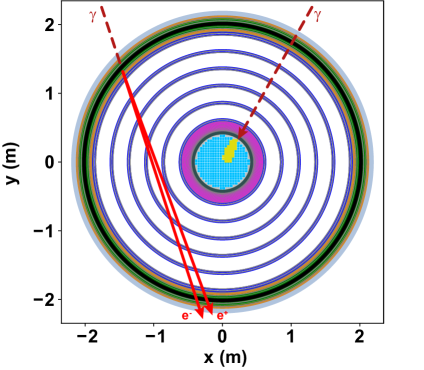
At low energies the angular resolution for converted photons is limited by multiple scattering of the resulting electron-positron pairs. But at high energies, the direction of the photon can be reconstructed with high accuracy due to the good spatial resolution and long lever arm of the silicon tracker (Fig. 15). This will resolve structures in -ray sources with angular resolution similar to today’s best X-ray telescopes. Interesting targets include galactic supernova remnants [109, 110], pulsar wind nebulae [111], and blazars. For converted photons perpendicular to the -axis the effective area reaches .
Due to the rotational symmetry of its barrel detector, its dedicated endcap photon detector, and its location far from the shadow of the Earth, AMS-100 will be able to monitor almost the entire sky continuously. Combined with its large effective area, this will make it a prime instrument for instantaneous observation of transient sources, e.g. -ray bursts or photons emitted in conjunction with gravitational wave events, as well as for monitoring blazar variability [114]. In combination with ground-based experiments, it will allow completing the multi-messenger network for modern astronomy combining the observation of gravitational waves, cosmic-ray neutrinos and GeV-TeV rays. AMS-100 can serve as a trigger for the Cherenkov Telescope Array [115] and similar ground-based observatories for the detailed follow-up investigation of transient sources.
The physics program of AMS-100 covering galactic and extragalactic -ray sources will be detailed in future publications. One example is the study of -ray pair halos around blazars, e.g. [116]. TeV rays emitted from the jets of blazars produce pairs of electrons and positrons through interactions with the extragalactic background light (EBL). These electrons and positrons further lose their energy through synchrotron and inverse Compton emission, thus initiating a cascade of lower-energy electrons, positrons and rays. Depending on the properties of the intergalactic magnetic fields, rays from such cascades can be observed in the form of extended -ray halos. With its improved diffuse sensitivity, AMS-100 would be able to detect or constrain the existence of pair halos and thus put new bounds on the strength and correlation length of the intergalactic magnetic field.
One can also search for spectral features in the -ray emission
of blazars due to attenuation from the EBL. This allows drawing
conclusions on axion-photon couplings [54, 55]. Measuring blazar
spectra to higher energies with AMS-100 extends the sensitive
parameter space to smaller couplings.
The excellent timing and pointing capabilities of AMS-100 make it an ideal instrument to test Lorentz invariance violation (LIV) by precisely measuring the energy and arrival time of photons from -ray bursts [56]. Deviations of the group velocity of photons from the speed of light, which could be realised in models of quantum gravity, would manifest themselves in different arrival times of photons of different energies from the same transient event. Given the energy reach of AMS-100, the observation of very high-energy rays in conjunction with X-ray instruments would increase the sensitivity to LIV by orders of magnitude compared to existing measurements.
4.7 AMS-100 Pathfinder
The technical complexity of the AMS-100 project requires a pathfinder mission, similar to the AMS-01 flight on Space Shuttle Discovery in 1998 [117], or to the ongoing LISA program. This pathfinder mission has to demonstrate the stable operation of a HTS magnet in space for the first time, including the expandable compensation coil technology. It has to be operated at L2 to verify the thermo-mechanical design and to demonstrate the sufficient attitude control inside the time-varying interplanetary magnetic field. Testing the quench probability of the magnet system in this environment and the impact of a quench on the instrument is of key importance. The successful test will qualify similar HTS magnet configurations as radiation shield for a crew compartment for interplanetary manned space flights as discussed in Ref. [36].
Given the effort of a space mission at L2, a purely technical demonstrator mission would be a waste of resources. Therefore the AMS-100 pathfinder is anticipated to be a prototype at the 10% scale level of AMS-100, i.e. the length and the radius of the main solenoid are reduced by a factor 2 to and , so that the instrumented volume is reduced by nearly an order of magnitude. Its weight is estimated to be and its detector concept is in all other aspects very similar to AMS-100. The central calorimeter has to be removed due to weight constraints as other components like the service module do not scale accordingly. With these dimensions and weight, the AMS-100 pathfinder can be launched to L2 with an Ariane 5 or a rocket of similar scale.
For the physics program of the pathfinder mission, the key performance parameters are a geometrical acceptance of and an MDR of . The sensitivity for heavy cosmic antimatter particles would be reduced compared to AMS-100 by an order of magnitude, but compared to AMS-02 this 10% scale pathfinder already has a higher sensitivity to heavy cosmic antimatter particles and completely independent systematic uncertainties, due to its different detector geometry, detector technology and orbit.
4.8 Cost estimates and timeline
| R&D phase | 2019 - 2021 |
|---|---|
| Detailed technical design report | 2020 - 2022 |
| Construction phase AMS-100 Pathfinder | 2023 - 2028 |
| Launch AMS-100 Pathfinder | 2029 |
| Science AMS-100 Pathfinder | 2030 - 2036 |
| Construction phase AMS-100 | 2031 - 2038 |
| Launch AMS-100 | 2039 |
| Science AMS-100 | 2040 - 2050 |
The AMS-100 project falls into the ESA or NASA class L category, i.e. the full mission requires a budget of more than 1 billion dollars. The scale of the project requires a large international collaboration as successfully demonstrated by the AMS-02 project on the International Space Station. The AMS-100 pathfinder mission falls into the ESA class M category or NASA class S category, i.e. it requires a budget below 500 million dollars, with an estimated instrument cost of 150 million dollars.
A possible timeline for the AMS-100 project is given in table 4. The important milestones for the R&D-Phase are the first successful space qualification test of a high temperature superconducting solenoid and the verification of the achievable time resolution of the ToF system. The detailed technical design report requires a valid thermo-mechanical model for the mission including a detailed concept of the detector electronics, DAQ system and data handling.
We welcome and invite contributions from interested groups with the goal of participating in the R&D-Phase and creating the technical design report for the AMS-100 project.
5 Summary
The only magnetic spectrometer in space today, AMS-02, has collected more than 140 billion cosmic rays since 2011 and will continue to take data for the lifetime of the ISS, i.e. the next decade. AMS-100 is an ambitious project for the following decade which requires pushing today’s technology to its limits in several fields. Many demanding technical questions need to be worked out in detail to make such a large space mission possible. These questions are of similar complexity as the ones that had to be solved to realize AMS-02 after the proposal in 1994 [118]. The AMS-100 concept as outlined in this article (Tab. 5) has the potential to improve the sensitivity of AMS-02 by a factor of 1000. This means that we will reproduce 20 years of AMS-02 data within the first week of operation at Lagrange Point 2. In the second week, we will start exploring completely new territory in precision cosmic-ray physics.
| Quantity | Value | |
|---|---|---|
| Acceptance | ||
| MDR | for | |
| Material budget | ||
| of main solenoid | ||
| Calorimeter depth | , | |
| Energy reach | for nucleons | |
| for , | ||
| for | ||
| Angular resolution | for photons at | |
| for photons at | ||
| Spatial resolution (SciFi) | ||
| Spatial resoultion (Si-Tracker) | ||
| Time resolution of single ToF bar | ||
| Incoming particle rate | ||
| High-level trigger rate | few kHz | |
| Downlink data rate | ||
| Instrument weight | ||
| Number of readout channels | 8 million | |
| Power consumption | ||
| Mission flight time | 10 years |
Acknowledgments
We thank the ACE/MAG instrument team and the ACE Science Center for providing the ACE data.
References
References
- Picozza et al. [2007] P. Picozza et al., Astroparticle Physics 27 (2007) 296–315. doi:10.1016/j.astropartphys.2006.12.002.
- Atwood et al. [2009] W. B. Atwood et al., The Astrophysical Journal 697 (2009) 1071–1102. doi:10.1088/0004-637x/697/2/1071.
- Kounine [2012] A. Kounine, International Journal of Modern Physics E 21 (2012) 30005. doi:10.1142/S0218301312300056.
- Marrocchesi [2015] P. S. Marrocchesi, Journal of Physics: Conference Series 718 (2015). doi:10.1088/1742-6596/718/5/052023.
- Gargano [2017] F. Gargano, Journal of Physics: Conference Series 934 (2017) 012015. doi:10.1088/1742-6596/934/1/012015.
- Aguilar et al. [2018] M. Aguilar et al. (AMS Collaboration), Phys. Rev. Lett. 121 (2018) 051103. doi:10.1103/PhysRevLett.121.051103.
- Aguilar et al. [2019] M. Aguilar et al. (AMS Collaboration), Phys. Rev. Lett. 122 (2019) 101101. doi:10.1103/PhysRevLett.122.101101.
- Aguilar et al. [2016] M. Aguilar et al. (AMS Collaboration), Phys. Rev. Lett. 117 (2016) 091103. doi:10.1103/physrevlett.117.091103.
- Aguilar et al. [2019] M. Aguilar et al. (AMS Collaboration), Phys. Rev. Lett. 122 (2019) 041102. doi:10.1103/PhysRevLett.122.041102.
- Klasen et al. [2015] M. Klasen, M. Pohl, and G. Sigl, Prog. Part. Nucl. Phys. 85 (2015) 1–32. doi:10.1016/j.ppnp.2015.07.001.
- Jóhannesson et al. [2018] G. Jóhannesson, T. A. Porter, and I. V. Moskalenko, The Astrophysical Journal 856 (2018) 45. doi:10.3847/1538-4357/aab26e.
- Gabici et al. [2019] S. Gabici, C. Evoli, D. Gaggero, P. Lipari, P. Mertsch, E. Orlando, A. Strong, and A. Vittino (2019). arXiv:1903.11584.
- Ting [2018] S. C. C. Ting, Latest Results from the AMS Experiment on the International Space Station, 2018. URL: https://cds.cern.ch/record/2320166, presented in the CERN Colloquium on 24th May 2018.
- Yamamoto et al. [1994] A. Yamamoto et al., Advances in Space Research 14 (1994) 75 -- 87. doi:10.1016/0273-1177(94)90071-X.
- XMM-Newton Community Support Team [2018] XMM-Newton Community Support Team, XMM-Newton Users Handbook, 2018. URL: https://www.cosmos.esa.int/web/xmm-newton/documentation.
- Selvamanickam et al. [2009] V. Selvamanickam et al., IEEE Transactions on Applied Superconductivity 19 (2009) 3225--3230. doi:10.1109/TASC.2009.2018792.
- Senatore et al. [2014] C. Senatore, M. Alessandrini, A. Lucarelli, R. Tediosi, D. Uglietti, and Y. Iwasa, Superconductor Science and Technology 27 (2014) 103001. doi:10.1088/0953-2048/27/10/103001.
- Benkel et al. [2017] T. Benkel et al., Eur. Phys. J. Appl. Phys. 79 (2017) 30601. doi:10.1051/epjap/2017160430.
- Barth et al. [2015] C. Barth, G. Mondonico, and C. Senatore, Superconductor Science and Technology 28 (2015) 045011. doi:10.1088/0953-2048/28/4/045011.
- Ilin et al. [2015] K. Ilin et al., Superconductor Science and Technology 28 (2015) 055006. doi:10.1088/0953-2048/28/5/055006.
- M. Daibo (2019) [Fujikura] M. Daibo (Fujikura), Recent Progress of 2G HTS wires and coils at Fujikura, 2019. URL: https://conference-indico.kek.jp/indico/event/62/contribution/22/material/slides/0.pdf, presentation at Workshop on Advanced Superconducting Materials and Magnets, Jan. 2019, KEK, Japan.
- SuperPower Inc. [2019] SuperPower Inc., 2G HTS Wire, accessed 5th June 2019. URL: http://www.superpower-inc.com/content/2g-hts-wire.
- Fujikura Ltd [2019] Fujikura Ltd, Introduction of FUJIKURA Yttrium-based Superconducting Wire, accessed 5th June 2019. URL: http://www.fujikura.co.jp/eng/products/newbusiness/superconductors/01/superconductor.pdf.
- Zhao et al. [2019] Y. Zhao, J.-M. Zhu, G.-Y. Jiang, C.-S. Chen, W. Wu, Z.-W. Zhang, S. K. Chen, Y. M. Hong, Z.-Y. Hong, Z.-J. Jin, and Y. Yamada, Superconductor Science and Technology 32 (2019) 044004. doi:10.1088/1361-6668/aafea5.
- Uglietti and Marinucci [2012] D. Uglietti and C. Marinucci, IEEE Transactions on Applied Superconductivity 22 (2012) 4702704. doi:10.1109/TASC.2011.2176455.
- Bae et al. [2015] J. H. Bae, Y. W. Jeong, and D. W. Ha, IEEE Transactions on Applied Superconductivity 25 (2015) 6605704. doi:10.1109/TASC.2014.2378911.
- Bonura and Senatore [2016] M. Bonura and C. Senatore, Applied Physics Letters 108 (2016) 242602. doi:10.1063/1.4954165.
- Hahn et al. [2011] S. Hahn, D. K. Park, J. Bascunan, and Y. Iwasa, IEEE Transactions on Applied Superconductivity 21 (2011) 1592--1595. doi:10.1109/TASC.2010.2093492.
- Yanagisawa et al. [2014] Y. Yanagisawa et al., Physica C: Superconductivity 499 (2014) 40 -- 44. doi:10.1016/j.physc.2014.02.002.
- Suetomi et al. [2019] Y. Suetomi et al., Superconductor Science and Technology 32 (2019) 045003. doi:10.1088/1361-6668/ab016e.
- Lalitha [2017] S. Lalitha, Cryogenics 86 (2017) 7 -- 16. doi:10.1016/j.cryogenics.2017.06.003.
- Erpenbeck [2019] H. Erpenbeck, Measurements of Scintillating Fiber Tracking Devices at Cryogenic Temperatures, 2019. BSc thesis, RWTH Aachen.
- Iwasa [2009] Y. Iwasa, Case Studies in Superconducting Magnets, Springer US, 2009. doi:10.1007/b112047.
- Parker [2001] E. N. Parker, Journal of Geophysical Research: Space Physics 106 (2001) 15797--15801. doi:10.1029/2000JA000100.
- ace [2019] ACE MAG Interplanetary Magnetic field, level 2 data, 2019. URL: http://www.srl.caltech.edu/ACE/ASC/level2/mag_l2desc.html.
- Westover et al. [2019] S. Westover et al., Radiation Protection and Architecture Utilizing High Temperature Superconducting Magnets, Technical Report, NASA Johnson Space Center, 2019. URL: https://www.nasa.gov/directorates/spacetech/niac/2012_Phase_II_Radiation_Protection_and_Architecture/.
- Thiesen et al. [2010] H. Thiesen et al., in: Proceedings of IPAC’10, Kyoto, Japan. URL: http://accelconf.web.cern.ch/Accelconf/IPAC10/papers/wepd070.pdf.
- Beischer et al. [2010] B. Beischer et al., Nucl. Instrum. Meth. A 622 (2010) 542--554. doi:10.1016/j.nima.2010.07.059.
- Kirn [2017] T. Kirn, Nucl. Instrum. Meth. A 845 (2017) 481--485. doi:10.1016/j.nima.2016.06.057, proceedings of the Vienna Conference on Instrumentation 2016.
- Alcaraz et al. [2008] J. Alcaraz et al., Nucl. Instrum. Meth. A 593 (2008) 376--398. doi:10.1016/j.nima.2008.05.015.
- Zhang et al. [2014] S. N. Zhang et al., in: Proceedings of the SPIE, volume 9144. doi:10.1117/12.2055280. arXiv:1407.4866.
- Galper et al. [2018] A. M. Galper, N. P. Topchiev, and Y. T. Yurkin, Astronomy Reports 62 (2018) 882--889. doi:10.1134/S1063772918120223.
- Arenberg et al. [2016] J. Arenberg, J. Flynn, A. Cohen, R. Lynch, and J. Cooper, in: Proc. SPIE 9904, Space Telescopes and Instrumentation 2016: Optical, Infrared, and Millimeter Wave, p. 990405. doi:10.1117/12.2234481.
- Chatrchyan et al. [2008] S. Chatrchyan et al., Journal of Instrumentation 3 (2008) S08004--S08004. doi:10.1088/1748-0221/3/08/s08004.
- CMS Collaboration [2017] CMS Collaboration, Technical Proposal For A MIP Timing Detector in the CMS Experiment Phase 2 Upgrade, Technical Report CERN-LHCC-2017-027. LHCC-P-009, CERN, Geneva, 2017. URL: https://cds.cern.ch/record/2296612.
- PANDA Collaboration [2018] PANDA Collaboration, Technical Design Report for the PANDA Barrel TOF, Technical Report, GSI, 2018. URL: https://panda.gsi.de/system/files/user_uploads/ken.suzuki/RE-TDR-2016-003_0.pdf.
- Rybczyński et al. [2005] M. Rybczyński, Z. Włodarczyk, and G. Wilk, International Journal of Modern Physics A 20 (2005) 6724--6726. doi:10.1142/S0217751X05029939.
- Tanabashi et al. [2018] M. Tanabashi et al. (Particle Data Group), Phys. Rev. D 98 (2018) 030001. doi:10.1103/PhysRevD.98.030001.
- Fuke et al. [2008] H. Fuke et al. (BESS Collaboration), Advances in Space Research 41 (2008) 2050 -- 2055. doi:10.1016/j.asr.2007.02.042.
- Hawking [1975] S. W. Hawking, Comm. Math. Phys. 43 (1975) 199--220. doi:10.1007/BF02345020.
- Maki et al. [1996] K. Maki, T. Mitsui, and S. Orito, Phys. Rev. Lett. 76 (1996) 3474--3477. doi:10.1103/PhysRevLett.76.3474.
- Bergström et al. [1998] L. Bergström, P. Ullio, and J. H. Buckley, Astropart. Phys. 9 (1998) 137--162. doi:10.1016/S0927-6505(98)00015-2.
- Bergström et al. [2012] L. Bergström, G. Bertone, J. Conrad, C. Farnier, and C. Weniger, JCAP 1211 (2012) 025. doi:10.1088/1475-7516/2012/11/025.
- Raffelt and Stodolsky [1988] G. Raffelt and L. Stodolsky, Phys. Rev. D37 (1988) 1237. doi:10.1103/PhysRevD.37.1237.
- De Angelis et al. [2007] A. De Angelis, M. Roncadelli, and O. Mansutti, Phys. Rev. D76 (2007) 121301. doi:10.1103/PhysRevD.76.121301.
- Amelino-Camelia et al. [1998] G. Amelino-Camelia, J. Ellis, N. E. Mavromatos, D. V. Nanopoulos, and S. Sarkar, Nature 393 (1998) 763--765. doi:10.1038/31647.
- Agostinelli et al. [2003] S. Agostinelli et al. (GEANT4 Collaboration), Nucl. Instrum. Meth. A 506 (2003) 250--303. doi:10.1016/S0168-9002(03)01368-8.
- Aguilar et al. [2015] M. Aguilar et al. (AMS Collaboration), Phys. Rev. Lett. 114 (2015) 171103. doi:10.1103/physrevlett.114.171103.
- Adriani et al. [2011] O. Adriani et al. (PAMELA Collaboration), Science 332 (2011) 69. doi:10.1126/science.1199172.
- Aguilar et al. [2017] M. Aguilar et al. (AMS Collaboration), Phys. Rev. Lett. 119 (2017) 251101. doi:10.1103/PhysRevLett.119.251101.
- Evoli et al. [2018] C. Evoli, P. Blasi, G. Morlino, and R. Aloisio, Phys. Rev. Lett. 121 (2018) 021102. doi:10.1103/PhysRevLett.121.021102.
- Génolini et al. [2017] Y. Génolini et al., Phys. Rev. Lett. 119 (2017) 241101. doi:10.1103/PhysRevLett.119.241101.
- Abe et al. [2016] K. Abe et al. (BESS Collaboration), The Astrophysical Journal 822 (2016) 65. doi:10.3847/0004-637x/822/2/65.
- Adriani et al. [2011] O. Adriani et al. (PAMELA Collaboration), Science 332 (2011) 69--72. doi:10.1126/science.1199172.
- Panov et al. [2009] A. D. Panov et al. (ATIC-2 Collaboration), Bulletin of the Russian Academy of Sciences: Physics 73 (2009) 564--567. doi:10.3103/S1062873809050098.
- Adriani et al. [2019] O. Adriani et al. (CALET Collaboration), Phys. Rev. Lett. 122 (2019) 181102. doi:10.1103/PhysRevLett.122.181102.
- Yoon et al. [2017] Y. S. Yoon et al. (CREAM Collaboration)), The Astrophysical Journal 839 (2017) 5. doi:10.3847/1538-4357/aa68e4.
- Lipari [2017] P. Lipari, Phys. Rev. D95 (2017) 063009. doi:10.1103/PhysRevD.95.063009.
- Cowsik et al. [2014] R. Cowsik, B. Burch, and T. Madziwa-Nussinov, Astrophys. J. 786 (2014) 124. doi:10.1088/0004-637X/786/2/124.
- Blum et al. [2013] K. Blum, B. Katz, and E. Waxman, Phys. Rev. Lett. 111 (2013) 211101. doi:10.1103/PhysRevLett.111.211101.
- Fujita et al. [2009] Y. Fujita, K. Kohri, R. Yamazaki, and K. Ioka, Phys. Rev. D80 (2009) 063003. doi:10.1103/PhysRevD.80.063003.
- Serpico [2012] P. D. Serpico, Astropart. Phys. 39-40 (2012) 2--11. doi:10.1016/j.astropartphys.2011.08.007.
- Linden and Profumo [2013] T. Linden and S. Profumo, Astrophys. J. 772 (2013) 18. doi:10.1088/0004-637X/772/1/18.
- Mertsch and Sarkar [2014] P. Mertsch and S. Sarkar, Physical Review D 90 (2014) 061301. doi:10.1103/PhysRevD.90.061301.
- Tomassetti and Donato [2015] N. Tomassetti and F. Donato, Astrophys. J. 803 (2015) L15. doi:10.1088/2041-8205/803/2/L15.
- Hooper et al. [2017] D. Hooper, I. Cholis, T. Linden, and K. Fang, Phys. Rev. D96 (2017) 103013. doi:10.1103/PhysRevD.96.103013.
- Liu et al. [2017] W. Liu, X.-J. Bi, S.-J. Lin, B.-B. Wang, and P.-F. Yin, Phys. Rev. D96 (2017) 023006. doi:10.1103/PhysRevD.96.023006.
- Kachelrieß et al. [2018] M. Kachelrieß, A. Neronov, and D. V. Semikoz, Phys. Rev. D97 (2018) 063011. doi:10.1103/PhysRevD.97.063011. arXiv:1710.02321.
- Profumo et al. [2018] S. Profumo, J. Reynoso-Cordova, N. Kaaz, and M. Silverman, Phys. Rev. D97 (2018) 123008. doi:10.1103/PhysRevD.97.123008.
- Turner and Wilczek [1990] M. S. Turner and F. Wilczek, Phys. Rev. D42 (1990) 1001--1007. doi:10.1103/PhysRevD.42.1001.
- Ellis [2000] J. R. Ellis, AIP Conf. Proc. 516 (2000) 21. doi:10.1063/1.1291467.
- Cheng et al. [2002] H.-C. Cheng, J. L. Feng, and K. T. Matchev, Phys. Rev. Lett. 89 (2002) 211301. doi:10.1103/PhysRevLett.89.211301.
- Cirelli et al. [2009] M. Cirelli, M. Kadastik, M. Raidal, and A. Strumia, Nucl. Phys. B 813 (2009) 1--21. doi:10.1016/j.nuclphysb.2008.11.031, [Addendum: Nucl. Phys. B 873 (2013) 530].
- Kane et al. [2009] G. Kane, R. Lu, and S. Watson, Phys. Lett. B681 (2009) 151--160. doi:10.1016/j.physletb.2009.09.053.
- Kopp [2013] J. Kopp, Phys. Rev. D88 (2013) 076013. doi:10.1103/PhysRevD.88.076013.
- Chen et al. [2015] C.-H. Chen, C.-W. Chiang, and T. Nomura, Phys. Lett. B747 (2015) 495--499. doi:10.1016/j.physletb.2015.06.035.
- Cheng et al. [2017] H.-C. Cheng, W.-C. Huang, X. Huang, I. Low, Y.-L. S. Tsai, and Q. Yuan, JCAP 1703 (2017) 041. doi:10.1088/1475-7516/2017/03/041.
- Bai et al. [2018] Y. Bai, J. Berger, and S. Lu, Phys. Rev. D97 (2018) 115012. doi:10.1103/PhysRevD.97.115012.
- Adriani et al. [2013] O. Adriani et al. (PAMELA Collaboration), Phys. Rev. Lett. 111 (2013) 081102. doi:10.1103/PhysRevLett.111.081102.
- Aharonian et al. [2009] F. Aharonian et al. (H.E.S.S. Collaboration), Astronomy and Astrophysics 508 (2009) 561--564. doi:10.1051/0004-6361/200913323.
- Ambrosi et al. [2017] G. Ambrosi et al. (DAMPE Collaboration), Nature 552 (2017) 63--66. doi:10.1038/nature24475.
- Adriani et al. [2011] O. Adriani et al. (PAMELA Collaboration), Phys. Rev. Lett. 106 (2011) 201101. doi:10.1103/PhysRevLett.106.201101.
- Adriani et al. [2018] O. Adriani et al. (CALET Collaboration), Phys. Rev. Lett. 120 (2018) 261102. doi:10.1103/PhysRevLett.120.261102.
- Abdollahi et al. [2017] S. Abdollahi et al. (Fermi-LAT Collaboration), Physical Review D 95 (2017) 082007. doi:10.1103/PhysRevD.95.082007.
- Aharonian et al. [2008] F. Aharonian et al. (H.E.S.S. Collaboration), Phys. Rev. Lett. 101 (2008) 261104. doi:10.1103/PhysRevLett.101.261104.
- Jóhannesson et al. [2016] G. Jóhannesson et al., Astrophys. J. 824 (2016) 16. doi:10.3847/0004-637X/824/1/16.
- Abe et al. [2012] K. Abe et al. (BESS Collaboration), Phys. Rev. Lett. 108 (2012) 051102. doi:10.1103/PhysRevLett.108.051102.
- Adriani et al. [2013] O. Adriani et al. (PAMELA Collaboration), JETP Letters 96 (2013) 621--627. doi:10.1134/S002136401222002X.
- Aramaki et al. [2016] T. Aramaki et al., Astroparticle Physics 74 (2016) 6--13. doi:10.1016/j.astropartphys.2015.09.001.
- Choutko and Giovacchini [2008] V. Choutko and F. Giovacchini, in: Proc. 30th ICRC, volume 4, pp. 765--768. URL: http://adsabs.harvard.edu/abs/2008ICRC....4..765C.
- Donato et al. [2000] F. Donato, N. Fornengo, and P. Salati, Phys. Rev. D62 (2000) 043003. doi:10.1103/PhysRevD.62.043003.
- Cui et al. [2010] Y. Cui, J. D. Mason, and L. Randall, Journal of High Energy Physics 2010 (2010) 17. doi:10.1007/JHEP11(2010)017.
- Fuke et al. [2005] H. Fuke et al., Phys. Rev. Lett. 95 (2005) 081101. doi:10.1103/PhysRevLett.95.081101.
- Chardonnet et al. [1997] P. Chardonnet, J. Orloff, and P. Salati, Physics Letters B 409 (1997) 313--320. doi:10.1016/S0370-2693(97)00870-8.
- Korsmeier et al. [2018] M. Korsmeier, F. Donato, and N. Fornengo, Physical Review D 97 (2018) 103011. doi:10.1103/physrevd.97.103011.
- Lin et al. [2018] S.-J. Lin, X.-J. Bi, and P.-F. Yin, arXiv e-prints (2018). arXiv:1801.00997.
- Aguilar et al. [2014] M. Aguilar et al. (AMS Collaboration), Phys. Rev. Lett. 113 (2014) 121102. doi:10.1103/PhysRevLett.113.121102.
- Ajello et al. [2017] M. Ajello et al., The Astrophysical Journal Supplement Series 232 (2017) 18. doi:10.3847/1538-4365/aa8221.
- Aharonian [2013] F. A. Aharonian, Astroparticle Physics 43 (2013) 71 -- 80. doi:https://doi.org/10.1016/j.astropartphys.2012.08.007.
- Funk [2017] S. Funk, High-Energy Gamma Rays from Supernova Remnants, Springer International Publishing, Cham, 2017, pp. 1737--1750. doi:10.1007/978-3-319-21846-5_12.
- Gaensler and Slane [2006] B. M. Gaensler and P. O. Slane, Ann. Rev. Astron. Astrophys. 44 (2006) 17--47. doi:10.1146/annurev.astro.44.051905.092528.
- Galper et al. [2017] A. M. Galper et al., Physics of Atomic Nuclei 80 (2017) 1141--1145. doi:10.1134/S1063778817060096.
- Fermi-LAT Collaboration [2019] Fermi-LAT Collaboration, Fermi LAT Performance, 2019. URL: http://www.slac.stanford.edu/exp/glast/groups/canda/lat_Performance_files/gPsfAve95Energy_P8R2_SOURCE_V6fb_10MeV.png.
- Bretz and Dorner [2019] T. Bretz and D. Dorner (Eds.), Monitoring the Non-Thermal Universe, special issue of Galaxies, 2019. URL: https://www.mdpi.com/journal/galaxies/special_issues/non-thermalUniverse.
- Acharya et al. [2013] B. S. Acharya et al., Astroparticle Physics 43 (2013) 3 -- 18. doi:10.1016/j.astropartphys.2013.01.007.
- Neronov and Vovk [2010] A. Neronov and I. Vovk, Science 328 (2010) 73--75. doi:10.1126/science.1184192.
- Aguilar et al. [2002] M. Aguilar et al. (AMS Collaboration), Physics Reports 366 (2002) 331--405.
- Ahlen et al. [1994] S. Ahlen et al., Nucl. Instrum. Meth. A 350 (1994) 351--367. doi:10.1016/0168-9002(94)91184-3.