Low-Loss High-Fidelity Frequency-Mode Hadamard Gates Based on Electromagnetically Induced Transparency
Abstract
A frequency beam splitter (FBS) with the split ratio of 0.5 or 1 can be used as the frequency-mode Hadamard gate (FHG) for frequency-encoded photonic qubits or as the quantum frequency converter (QFC) for frequency up or down conversion of photons. Previous works revealed that all kinds of the FHG or QFC operating at the single-photon level had overall efficiency or output-to-input ratio around 50% or less. In this work, our FHG and QFC are made with the four-wave mixing process based on the dual- electromagnetically induced transparency scheme. We achieved an overall efficiency of 904% in the FGH and that of 84% in the QFC using coherent-state single photons, both of which are the best up-to-date records. To test the fidelity of the FBS, we propose a novel scheme of Hong-Ou-Mandel interference (HOMI) for quantum process tomography. The fidelity indicated by the HOMI’s measurement of the FHG is 0.990.01. Such low-loss high-fidelity FHG and QFC or FBS with the tunable split ratio can lead to useful operations or devices in long-distance quantum communication.
Quantum information or wave functions is commonly encoded in photons’ polarization or spatial mode. As compared with these two kinds of photonic qubits, frequency-encoded qubits are not only more stable over long transmission distances but also more robust against birefringent materials OE2011 ; PRA2014 ; SSL2014 ; NPhot2016 ; Optica2017 ; PRL2018 . Among quantum logic operations, the Hadamard gate is an essential component. A beam splitter is exactly the Hadamard gate for spatial-mode qubits. In the context of frequency-encoded photonic qubits, a frequency beam splitter (FBS) is the Hadamard gate. In this work, we demonstrate a FBS with a tunable split ratio, where the split ratio is the ratio of photon number in one output frequency mode to total output photon number. At the split ratio of 0.5, a FBS, i.e., a 50/50 FBS, can be employed as the frequency-mode Hadamard gate (FHG). At the split ratio of 1, a FBS can be utilized as the quantum frequency converter (QFC), which coherently converts a photonic qubit from one frequency or wavelength to another.
To date, all kinds of FHG and QFC operating at the single-photon level had output-to-input ratios or overall efficiencies (including decay due to propagation or insertion loss in media, input coupling efficiency, frequency conversion efficiency, etc.) around 50% or less NPhot2016 ; PRL2018 ; FWM3 ; FWM4 ; FWM5 ; FWM9 ; FWM10 ; FWM11 ; FWM12 ; FWM13 ; FWM14 ; FWM15 . Most of these works suffered large insertion loss induced by media, which not only reduces the output-to-input ratio but also may lead to additional quantum noise. Here, our low-loss FBS is made with the four-wave mixing (FWM) process based on the dual- electromagnetically induced transparency (EIT) scheme ReviewEIT ; EIT-FWM1 ; EIT-FWM2 ; EIT-FWM3 ; FWM1996 ; FWM2002 ; FWM2014 ; FWM2016 . Using the transition scheme depicted in Fig. 1(a), we converted a coherent-state single photon in the 780 nm mode to another photon in the superposition of 780 nm and 795 nm modes, and demonstrated that the FHG has an output-to-input ratio of 904%. Furthermore, we performed the QFC from 780 to 795 nm with light pulses of photon number less than one, and achieved an output-to-input ratio of 844%. Both output-to-input ratios are the best up-to-date records.
To test the fidelity of a quantum device or operation, one should perform quantum process tomography QPT1 ; QPT2 ; QPT3 ; QPT4 . We propose a novel method for quantum process tomography using Hong-Ou-Mandel interference (HOMI). HOMI1 ; HOMI2 ; HOMI3 ; HOMI4 ; HOMI5 . The HOMI is a two-photon phenomenon, in which one two-mode wave function formed by the two outputs of the FBS interferes with another. In the HOMI measurement of our FHG, the value of normalized cross correlation function, , reveals that the fidelity is 0.990.01. To our knowledge, this is the first time that the HOMI is used for quantum process tomography of a quantum logic gate. The result of high fidelity also indicates that the single-photon quantum state is well preserved in the dual- EIT scheme. The EIT mechanism is universal and can work for various media EIT1 ; EIT2 ; EIT3 ; EIT4 ; EIT5 . Hence, the high-fidelity and low loss FBS reported here can be readily applied to systems of the optical depth and decoherence rate similar to those in this work.
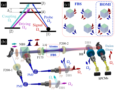
Our experiment was carried out with laser-cooled 87Rb atoms CigarMOT ; OurPRA2013 ; QM2013 . Figure 1(b) shows the schema of experimental setup. In the photon-atom coupling scheme as depicted in Fig. 1(a), the 780 nm probe and coupling fields form the first EIT configuration under the one-photon resonance; the 795 nm signal and driving fields form the second one with a large one-photon detuning, . The coupling and driving fields were strong quasi-cw light. The probe and signal fields were weak classical pulses, or coherent-state single- or few-photon pulses. Other details of the experimental system can be found in Sec. I of the Supplemental Material.
To characterize our experimental system and verify measurement outcomes, we made theoretical predictions with the optical Bloch equations (OBEs) of density-matrix operator and the Maxwell-Schrödinger equations (MSEs) of light fields, which can be found in Sec. II of the Supplemental Material. In these equations and thorough the paper, , , , and denote the Rabi frequencies of the coupling, driving, probe, and signal fields, is the two-photon detuning of the Raman transition between two ground states and , represents the ground-state decoherence rate, denotes the spontaneous decay rate of the excited states and which is about 6 MHz in our case, and is the optical depth (OD) of the medium. The measurements that determined , , , and in the experiment are illustrated in Sec. III of the Supplemental Material.
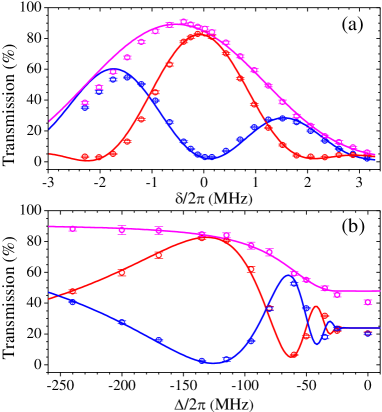
The split ratio here is defined as the ratio of 795 nm output photon number to total output photon number under the condition that only the 780 nm photons are present at the input. Tuning the split ratio of FBS can be done by varying either two-photon detuning or one-photon detuning . In this study of split ratio, only the 780 nm probe pulse of classical light was present at the input, and . A part of the 780 nm input pulse was converted to the 795 nm signal pulse at the output, and the remaining became the 780 nm output pulse. Figures 2(a) and 2(b) show the energy transmissions of 780 nm and 795 nm output pulses as functions of the two-photon detuning and the one-photon detuning , respectively. One can see that using to tune the split ratio can suffer a larger loss, and using is more efficient. In Fig. 2(b), the split ratio can be tuned from 1 to 0.5 or smaller with 130 MHz. The total energy transmission of 780 nm and 795 nm output pulses is 85% (or 88%) at the split ratio equal to 0.97 (or 0.54). A smaller split ratio results in a higher total transmission. In both figures, the apparent phenomenon of oscillation indicates that the underlying mechanism of FWM involves with the interference effect FWM2002 ; FWM2014 . The theoretical predictions were calculated by numerically solving OBEs and MSEs with the experimentally-determined parameters of , , , and OurPRA2013 ; QM2013 . Consistency between the experimental data and theoretical predictions is satisfactory.
To test whether the scheme of our FBS can also work well at the single-photon level, we performed the measurements with coherent-state pulses of photon number equal to or less than 1. Two etalon filters were installed to provide the extinction ratio of 43 dB. The etalons, together with the scheme of spatial filter (see the third paragraph in Sec. I of the Supplemental Material), can effectively block the strong coupling and driving light from entering single-photon counting modules (SPCMs). Two Excelitas SPCM-AQRH-13-FC were used to detect the 780 nm and 795 nm output photons. The collection efficiencies (including the SPCM’s quantum efficiency) of the 780 nm and 795 nm photons were about 0.13 and 0.12 for the data in Fig. 3(a) [0.17 and 0.12 for those in Fig. 3(b)]. We had another SPCM at the input to monitor the input photon number. All of the photo multiplier tubes used in the measurements of classical-light pulses and the SPCMs used in those of single-photon or few-photon pulses were calibrated to account for different detection efficiencies between the wavelengths or between the detectors. In each SPCM’s counting, it took 0.15 s to replenish cold atoms, switch off the MOT, perform the temporal dark-MOT, and optically pump all population to a single Zeeman state, before the input pulse was fired.
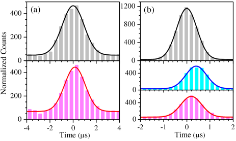
At the split ratio of 1, the FBS acts like a coherent wavelength converter transforming 780 nm photons completely into 795 nm photons. Figure 3(a) shows SCPM counts of input and output photons as functions of time. The best fit of the data in Fig. 3(a) is consistent with the result of classical light shown by Fig. S1(c) in Sec. III of the Supplemental Material. The baseline count was mainly contributed from the leakage of strong coupling or driving fields. Using the area below the best fit but excluding the baseline count, we determined the overall conversion efficiency from the 780 nm single photons to the 795 nm single photons or the output-to-input ratio is 844%.
The split ratio of 0.5 can make the 50/50 FBS or Hadamard gate for frequency-encoded photonic quits. In Fig. 3(b), SCPM counts of 780 nm input photons and those of 780 nm and 795 nm output photons are plotted against time. The best fits of the data in Fig. 3(b) are consistent with the results of classical light shown by Fig. S2(a) in Sec. IV of the Supplemental Material. The comparison between Figs. 3(a) and 3(b) indicates that employing a narrower single-photon pulse can increase the amplitude-to-baseline ratio, while the output-to-input ratio was nearly intact. In our 50/50 FBS, the total transmission or ratio of total output photons to input photons is 904%.
We have now made the FBS which can operate with single photons. In analogy to an ordinary BS, 780 nm (or 795 nm) input photons are reflected into 795 nm (or 780 nm) output photons and transmitted into 780 nm (795 nm) output photons by our FWM-based FBS, with the split ratio defined by the ratio of reflected output photon number to total output photon number. Figure 1(c) illustrates the operation of 50/50 FBS. The next question is whether this FBS can be suitable for quantum information processing. To answer the question, fidelity is the important issue and can be determined by the following formula Fidelity1 ; Fidelity2 ; PRL2018 :
| (1) |
where represents the operator of an ideal BS, represents the operator of FWM-based FBS in the case here, means the operation of trace, and is the total transmission or success probability of .
Considering the FBS, we define () and () as the transmission and reflection coefficients of input 1 (input 2), and () as the phase difference between the reflected and transmitted outputs. The general expression of is given by
| (2) |
The split ratio of two inputs are determined by and . In reality, the ground-state decoherence rate in the experimental system was not negligible, making two inputs produce different split ratios and . An ideal 50/50 BS must have . Corresponding to in Eq. (2) of a realistic BS with two split ratios close to 0.5, of the ideal 50/50 BS can be written as BS1 ; BS2
| (3) |
where . The derivation in Sec. V of the Supplemental Material shows that the fidelity of is
| (4) |
where , , , and .
According to Eq. (4), one can immediately see that the phase approaching to can make a high-fidelity FBS. To determine , we employed the Hong-Ou-Mandel interference (HOMI) HOMI1 ; HOMI2 ; HOMI3 ; HOMI4 ; HOMI5 , and measured the normalized cross correlation function, , between two outputs of the FBS. A simple example, to explain why the HOMI measurement can determine of Eq. (4), is illustrated in Sec. VI of the Supplemental Material. In the HOMI, it is well known that, with a 50/50 BS in the ideal condition, two Fock-state single photons results in HOMI1 ; HOMI2 , and two phase-uncorrelated coherent-state single photons results in = 0.5 HOMI3 ; HOMI4 ; HOMI5 . Here, we sent two pulses to the two input ports of 50/50 FBS in the HOMI measurement. Each pulse consisted of a coherent-state single photon or few photons. The wavelength of one pulse was 780 nm and that of the other was 795 nm. Since the two pulses had the same mean photon number and were phase-uncorrelated, the derivation in Sec. VII of the Supplemental Material shows that of the two output ports is given by
| (5) |
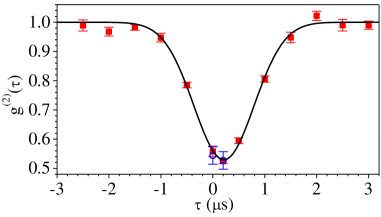
In Fig. 4, is plotted against the delay time between the two input pulses. The minimum is and occurs at the delay time of 200 ns. Based on the data shown in Figs. S2(a) and S2(b) of the Supplemental Material, this 200-ns delay time is expected. The two-photon event of both photons from two input ports transmitting through the FBS, and that of both photons being reflected by the FBS were nearly indistinguishable under such delay time. Right before taking the data in Fig. 4, we measured the data similar to those in Figs. S2(a) and S2(b), and found , , , and . The minimum and Eq. (5) result in . Finally, we use Eq. (4) and the above values of , , , , and to determine = 0.990.01, indicating that the FWM-based FBS possesses excellent fidelity.
In conclusion, utilizing the EIT-based FWM process we experimentally demonstrated the FBS with coherent-state single-photon pulses. At the split ratio of nearly 1, the FBS converted all of 780 nm input photons to 795 nm output photons with the output-to-input ratio of 844%, and can be employed as a quantum frequency converter. At the split ratio of 0.5, the FBS offered the output-to-input ratio of 904%, and can be employed as the Hadamard gate for frequency-encoded photonic qubits. Both of the output-to-input ratios or overall efficiencies are the best up-to-date records. To test the fidelity of the FBS, we proposed a method of the HOMI-type quantum process tomography, in which one two-mode wave function formed by two outputs of the Hadamard gate interferes with another. The value of in the HOMI measurement indicates that the fidelity of our frequency-mode Hadamard gate is 0.990.01. To our knowledge, it is the first time to utilize the HOMI in the quantum process tomography. This low-loss high-fidelity FBS with the tunable split ratio can lead to useful devices or operations, such as entanglement swapping, multiplexing, etc., in long-distance quantum communication.
ACKNOWLEDGMENTS
This work was supported by the Ministry of Science and Technology of Taiwan under Grant Nos. 106-2119-M-007-003 and 107-2745-M-007-001.
References
- (1) A. Eckstein, B. Brecht, and C. Silberhorn, A quantum pulse gate based on spectrally engineered sum frequency generation, Opt. Express 19, 13770 (2011).
- (2) B. Brecht, A. Eckstein, R. Ricken, V. Quiring, H. Suche, L. Sansoni, and C. Silberhorn, Demonstration of coherent time-frequency Schmidt mode selection using dispersion-engineered frequency conversion, Phys. Rev. A 90, 030302(R) (2014)
- (3) M.-J. Lee, J. Ruseckas, C.-Y. Lee, V. Kudriǎsov, K.-F. Chang, H.-W. Cho, G. Juzeliūnas, and I. A. Yu, Experimental demonstration of spinor slow light, Nat. Commun. 5, 5542 (2014).
- (4) J. M. Lukens and P. Lougovski, Frequency-encoded photonic qubits for scalable quantum information processing, Optica 4, 8 (2017).
- (5) T. Kobayashi, R. Ikuta, S. Yasui, S. Miki, T. Yamashita, H. Terai, T. Yamamoto, M. Koashi, and N. Imoto, Frequency-domain Hong-Ou-Mandel interference, Nat. Photon. 10, 441 (2016).
- (6) H.-H. Lu, J. M. Lukens, N. A. Peters, O. D. Odele, D. E. Leaird, A. M. Weiner, and P. Lougovski, Electro-Optic Frequency Beam Splitters and Tritters for High-Fidelity Photonic Quantum Information Processing, Phys. Rev. Lett. 120, 030502 (2018).
- (7) L. M. Duan, M. D. Lukin, J. I. Cirac, and P. Zoller, Long-distance quantum communication with atomic ensembles and linear optics, Nature 414, 413 (2001).
- (8) N. K. Langford, S. Ramelow, R. Prevedel, W. J. Munro, G. J. Milburn, and A. Zeilinger, Efficient quantum computing using coherent photon conversion, Nature 478, 360 (2011).
- (9) P. Kumar, Quantum frequency conversion, Opt. Lett. 15, 1476 (1990).
- (10) S. Tanzilli, W. Tittel, M. Halder, O. Alibart, P. Baldi, N. Gisin, and H. Zbinden, A photonic quantum information interface, Nature 437, 116 (2005).
- (11) M. T. Rakher, L. Ma, O. Slattery, X. Tang, and K. Srinivasan, Quantum transduction of telecommunications-band single photons from a quantum dot by frequency upconversion, Nat. Photon. 4, 786 (2010).
- (12) H. J. McGuinness, M. G. Raymer, C. J. McKinstrie, and S. Radic, Quantum Frequency Translation of Single-Photon States in a Photonic Crystal Fiber, Phys. Rev. Lett. 105, 093604 (2010).
- (13) S. Ates, I. Agha, A. Gulinatti, I. Rech, M. T. Rakher, A. Badolato, and K. Srinivasan, Two-Photon Interference Using Background-Free Quantum Frequency Conversion of Single Photons Emitted by an InAs Quantum Dot, Phys. Rev. Lett. 109, 147405 (2012).
- (14) A. S. Clark, S. Shahnia, M. J. Collins, C. Xiong, and B. J. Eggleton, High-efficiency frequency conversion in the single-photon regime, Opt. Lett. 38, 947 (2013).
- (15) Q. Li, M. Davanço, and K. Srinivasan, Efficient and low-noise single-photon-level frequency conversion interfaces using silicon nanophotonics, Nat. Photon. 10, 406 (2016).
- (16) S. Clemmen, A. Farsi, S. Ramelow, and A. Gaeta, Ramsey Interference with Single Photons, Phys. Rev. Lett. 117, 223601 (2016); A. Farsi, PhD thesis. Cornell University, 2015.
- (17) A. G. Radnaev, Y. O. Dudin, R. Zhao, H. H. Jen, S. D. Jenkins, A. Kuzmich, and T. A. B. Kennedy, A quantum memory with telecom-wavelength conversion, Nat. Phys. 6, 894 (2010).
- (18) G. Wang, Y. Xue, J.-H. Wu, Z.-H. Kang, Y. Jiang, S.-S. Liu, and J.-Y. Gao, Efficient frequency conversion induced by quantum constructive interference, Opt. Lett. 35, 3778 (2010).
- (19) Z.-Y. Liu, J.-T. Xiao, J.-K. Lin, J.-J. Wu, J.-Y. Juo, C.-Y. Cheng, and Y.-F. Chen, High-efficiency backward four-wave mixing by quantum interference, Sci. Rep. 7, 15796 (2017).
- (20) M. Jain, H. Xia, G. Y. Yin, J. Merriam, and S. E. Harris, Efficient Nonlinear Frequency Conversion with Maximal Atomic Coherence, Phys. Rev. Lett. 77, 4326 (1996).
- (21) M. G. Payne and L. Deng, Consequences of induced transparency in a double- scheme: Destructive interference in four-wave mixing, Phys. Rev. A 65, 063806 (2002).
- (22) C.-K. Chiu, Y.-H. Chen, Y.-C. Chen, I. A. Yu, Y.-C. Chen, and Y.-F. Chen, Low-light-level four-wave mixing by quantum interference, Phys. Rev. A 89, 023839 (2014).
- (23) C.-Y. Lee, B.-H. Wu, G. Wang, Y.-F. Chen, Y.-C. Chen, and I. A. Yu, High conversion efficiency in resonant four-wave mixing processes, Opt. Express 24, 1008 (2016).
- (24) M. Fleischhauer, A. Imamoglu, and J. Marangos, Electromagnetically induced transparency: Optics in coherent media, Rev. Mod. Phys. 77, 633 (2005).
- (25) A. M. Childs, I. L. Chuang, and D. W. Leung, Realization of quantum process tomography in NMR, Phys. Rev. A 64, 012314 (2001).
- (26) J. L. O’Brien, G. J. Pryde, A. Gilchrist, D. F. James, N. K. Langford, T. C. Ralph, and A. G. White, Quantum process tomography of a controlled-NOT gate, Phys. Rev. Lett. 93, 080502 (2004).
- (27) R. C. Bialczak, M. Ansmann, M. Hofheinz, E. Lucero, M. Neeley, A. D. O’Connell, D. Sank, H. Wang, J. Wenner, M. Steffen, A. N. Cleland, and J. M. Martinis, Quantum process tomography of a universal entangling gate implemented with Josephson phase qubits, Nat. Phys. 6, 409 (2010).
- (28) Y. Kim, Y.-S. Kim, S.-Y. Lee, S.-W. Han, S. Moon, Y.-H. Kim, and Y.-W. Cho, Direct quantum process tomography via measuring sequential weak values of incompatible observables, Nat. Commun. 9, 192 (2018).
- (29) C. K. Hong, Z. Y. Ou, and L. Mandel, Measurement of Subpicosecond Time Intervals between Two Photons by Interference, Phys. Rev. Lett. 59, 2044 (1987).
- (30) T. B. Pittman, D. V. Strekalov, A. Migdall, M. H. Rubin, A. V. Sergienko, and Y. H. Shih, Can Two-Photon Interference be Considered the Interference of Two Photons?, Phys. Rev. Lett. 77, 1917 (1996).
- (31) J. G. Rarity, P. R. Tapster, and R. Loudon, Non-classical interference between independent sources, J. Opt. B: Quantum Semiclass. Opt. 7, S171 (2005).
- (32) Y.-S. Kim, O. Slattery, P. S. Kuo, and X. Tang, Conditions for two-photon interference with coherent pulses, Phys. Rev. A 87, 063843 (2013).
- (33) H. Chen, X.-B. An, J. Wu, Z.-Q. Yin, S. Wang, W. Chen, and Z.-F. Han, Hong-Ou-Mandel interference with two independent weak coherent states, Chin. Phys. B 25, 020305 (2016).
- (34) S. Marcinkevičius, A. Gushterov, and J. P. Reithmaier, Transient electromagnetically induced transparency in self-assembled quantum dots, Appl. Phys. Lett. 92, 041113 (2008).
- (35) E. Ignesti, R. Buffa, L. Fini, E. Sali, M. V. Tognetti, S. Cavalieri, Controlling the propagation of broadband light pulses by Electromagnetically Induced Transparency, Opt. Commun. 285, 1185 (2012).
- (36) V. M. Acosta, K. Jensen, C. Santori, D. Budker, and R. G. Beausoleil, Electromagnetically Induced Transparency in a Diamond Spin Ensemble Enables All-Optical Electromagnetic Field Sensing, Phys. Rev. Lett. 110, 213605 (2013).
- (37) R. Akhmedzhanov, L. Gushchin, N. Nizov, V. Nizov, D. Sobgayda, I. Zelensky, and A. Kalachev, Electromagnetically induced transparency in an isotopically purified Nd3+:YLiF4 crystal, Phys. Rev. B 97, 245123 (2018).
- (38) J. Long, H. S. Ku, X. Wu, X. Gu, R. E. Lake, M. Bal, Y.-X. Liu, and D. P. Pappas, Electromagnetically Induced Transparency in Circuit Quantum Electrodynamics with Nested Polariton States, Phys. Rev. Lett. 120, 083602 (2018).
- (39) Y.-W. Lin, H.-C. Chou, P. P. Dwivedi, Y.-C. Chen, and I. A. Yu, Using a pair of rectangular coils in the MOT for the production of cold atom clouds with large optical density, Opt. Express 16, 3753 (2008).
- (40) Y.-H. Chen, M.-J. Lee, I.-C. Wang, S. Du, Y.-F. Chen, Y.-C. Chen, and I. A. Yu, Coherent Optical Memory with High Storage Efficiency and Large Fractional Delay, Phys. Rev. Lett. 110, 083601 (2013).
- (41) Y.-H. Chen, M.-J. Lee, I.-C. Wang, and I. A. Yu, Fidelity of electromagnetically-induced-transparency-based optical memory, Phys. Rev. A 88, 023805 (2013).
- (42) D. B. Uskov, L. Kaplan, A. M. Smith, S. D. Huver, and J. P. Dowling, Maximal success probabilities of linear-optical quantum gates, Phys. Rev. A 79, 042326 (2009).
- (43) S. Rahimi-Keshari, M. A. Broome, R. Fickler, A. Fedrizzi, T. C. Ralph, and A. G. White, Direct characterization of linear-optical networks, Opt. Express 21, 13450 (2013).
- (44) S. M. Barnett, J. Jeffers, and A. Gatti, Quantum optics of lossy beam splitters, Phys. Rev. A 57, 2134 (1998).
- (45) R. Uppu, T. A. W. Wolterink, T. B. H. Tentrup, and P. W. H. Pinkse, Quantum optics of lossy asymmetric beam splitters, Opt. Express 24, 16440 (2016).