COded Taking And Giving (COTAG): Enhancing Transport Layer Performance over Indoor Millimeter Wave Access Networks
Abstract
Millimeter wave (mmWave) access networks have the potential to meet the high-throughput and low-latency needs of immersive applications. However, due to the highly directional nature of the mmWave beams and their susceptibility to beam misalignment and blockage resulting from user movements and rotations, the associated mmWave links are vulnerable to large channel fluctuations. These fluctuations result in disproportionately adverse effects on performance of transport layer protocols such as Transmission Control Protocol (TCP). To overcome this challenge, we propose a network layer solution, COded Taking And Giving (COTAG) scheme to sustain low-latency and high-throughput end-to-end TCP performance in dually connected networks. In particular, COTAG creates network encoded packets at the network gateway and each access point (AP) aiming to adaptively take the spare bandwidth on each link for transmission. Further, if one link bandwidth drops due to user movements, COTAG actively abandons the transmission opportunity by conditionally dropping packets. Consequently, COTAG actively adapts to link quality changes in mmWave access network and enhances the TCP performance without jeopardizing the latency of immersive content delivery. To evaluate the effectiveness of the proposed COTAG, we conduct experiments using off-the-shelf APs and network simulations. The evaluation results show that COTAG improves end-to-end TCP performance significantly on both throughput and latency.
Index Terms:
mmWave Links, TCP, Dual Connectivity, Immersive Content, Network Coding.I Introduction
The demand for immersive content such as augmented reality (AR) and virtual reality (VR) is growing rapidly. These applications require high-throughput and low-latency network connectivity to support their rich, dynamic, and interactive content. They also need wireless connectivity for untethered access. In this paper, we assume that the wireless connectivity is primarily provided using millimeter wave (mmWave) based communication link. Note that, mmWave links have the potential to support high throughput because there is a large amount of spectrum available in this frequency band, e.g., Federal Communications Commission (FCC) has allocated 7 GHz (57 GHz – 64 GHz) of contiguous unlicensed spectrum for commercial and public use.
As the mmWave band brings the channel capacity to a new high level, there are also challenges. One challenge with the mmWave band is that the beams are substantially more directional than the conventional sub-6 GHz band. Furthermore, link bandwidth degrades more severely at the mmWave band than at the sub-6 GHz band [1, 2]. For example, the 60 GHz signal attenuates 15 to 20 dB for the first-order reflected path as compared to the line-of-sight (LOS) path. Although adaptive beam management can alleviate deterioration in channel conditions, detecting a change in the channel conditions as well as reforming the beams takes time. The delays incurred in adapting the beams adversely affect the end-to-end latency and the resulting end-to-end throughput, which in turn degrades AR/VR experience. Additionally, at certain frequencies especially around the 60 GHz band, the mmWave channels are highly susceptible to human blockages. Finally, although dual connectivity reduces end-to-end outage probability[3], the link quality imbalance in dual connectivity can impact upper-layer end-to-end throughput and latency.
AR/VR applications often use Transmission Control Protocol (TCP) to ensure reliable, sequenced delivery of packets from server to client. Due to the above characteristics of mmWave band and due to changes in user pose, location, and direction during AR/VR applications, TCP’s performance often falls well short of its performance in a comparable fully wired network. This is because human-induced channel quality deteriorations often causes the data rate to fall substantially. As a result, the bits in transit from the TCP sender to the TCP receiver experience severe congestion, which is sensed by the TCP sender after a certain network delay. Even after the lower layer protocols have largely restored the data rates, the TCP sender cannot sense this increase. Instead, in order to preserve network fairness, it slowly strives to increase the sending rate. While the sending rate is slowly increasing, the end-to-end throughput is substantially below the available bandwidth.
Although there are several potential solutions to this problem, it is very difficult to avoid the inherent delay for solutions at the transport layer to work effectively. The motivation of this paper is to enhance the transport layer end-to-end performance for indoor applications like AR/VR in dual connectivity mmWave network by alleviating impacts of channel fluctuations and link quality imbalance. We propose a network layer technique called COded Taking And Giving (COTAG) in this paper. COTAG assumes that there is a dual wireless connectivity to end user, through either two mmWave links or one mmWave link and one sub-6G link. An advantage of dual connectivity is that there will be no complete loss of connectivity unless both links are blocked simultaneously. COTAG encodes packets into linear combinations at the gateway of indoor wireless network and forwards these combinations of packets through the dual connectivity for decoding at the mobile device. During the forwarding, if spare bandwidth is available, COTAG also generates extra combinations to fully use the bandwidth. COTAG adaptively gives up transmission opportunity when one link does not have enough bandwidth and generates redundancy when there is adequate bandwidth. In this way, COTAG adapts to the changes in link quality and alleviates adverse effects of channel fluctuations and link quality imbalance to enhance TCP performance.
The rest of this paper is organized as follows. The related work is introduced in Section II. The proposed approach and algorithms are described in Section III. The evaluation results demonstrating the effectiveness of the proposed mechanism are presented in Section IV. Finally, the paper is summarized in Section V.
II Related Work
MPTCP. Transmission Control Protocol (TCP) is the most common transport layer scheme for reliable, sequenced delivery of data. There are many variants of TCP. The recent variants such as NewReno [4], CUBIC [5], Compound [6], and BBR [7] are designed for networks with high bandwidth delay products (BDP). However, they are not well suited for dealing with large bandwidth changes due to fluctuations in the wireless channel quality. Moreover, although TCP variants for wireless networks have been studied for dealing with packet errors and single channel fluctuations [8], further enhancement is needed for mmWave based dual connectivity networks to mitigate impacts from not only packet loss, but also imbalance in link quality. The TCP variant most related to the solution in this paper is Multipath TCP (MPTCP) [9].
MPTCP is a transport layer protocol designed to better utilize the bandwidth available across multiple paths in order to increase the end-to-end throughput. It tends to work well when the multiple paths from the source to the receiver are mostly edge disjoint. If there are many shared links among the paths, then the effectiveness is diminished. The effectiveness of MPTCP has been evaluated in delivering across multiple interfaces of an end host in [10]. [10] shows that the effectiveness of MPTCP is not satisfactory when the bandwidth of mmWave link fluctuates significantly over time.
To alleviate this problem, MuSher [11] adjusts the packet forwarding ratio according to the transport layer throughput and buffer conditions across the multiple paths in MPTCP. The adaptive packet scheduling at the transport layer in Musher enhances MPTCP performance in dual connectivity network with mmWave (IEEE 802.11ad) and sub-6G (IEEE 802.11ac) links. As compared to Musher, this paper addresses a network layer enhancement to the dual connectivity network for AR/VR scenario, where the frequent user movements, rotations and blockages result in significant channel fluctuations.
SRNC. Spare-bandwidth Rate-adaptive Network Coding (SRNC) is an approach to enhance TCP performances in a wireless mesh based network with gigabit links. The scheme proposed in this paper is inspired by the concept of network coding in SRNC. Due to the mesh networks, there are many paths with possibly many links with available bandwidth to provide many opportunities for network coding in [12]. Since packets from TCP flows destined for different end hosts are cross-coded, the decoding also occurs in the wireless mesh network. The end host is delivered unencoded packets and it is completely oblivious to the network coding that occurred in the mesh. Such cross-coding is not applicable to scenarios considered in this paper.
Other Related Work. Challenges of mmWave communications have been addressed at all layers of network stack. At physical layer, Sur et al. propose MUST to predict the best beam and to redirect user traffic over conventional WiFi when there is blockage in the mmWave link [13]. Although MUST focuses on the physical layer, it needs support from higher layers of the protocol to redirect user traffic.[3] discusses the challenges and tradeoffs of Ultra-Reliable Low Latency Communication (URLLC) considering massive MIMO and multi-connectivity. Using mmWave links cooperatively with LTE, 5G new radio (NR) are also being investigated in [10, 14]. Moreover, relaying video with mmWave based data plane and sub-6G based control plane is proposed in [15] to mitigate impacts of link failures in mmWave based relay networks. Non-Orthogonal Multiple Access (NOMA) supports the multi-user wireless networks for 5G NR in both power and code domains [16]. Besides the improvement achieved by NOMA for multi-user cases, enhancement at the higher layer is also important for more robust dual connectivity which may be supported by different base stations connected with the same user equipment.
III COded Taking And Giving (COTAG) Scheme
III-A Overview
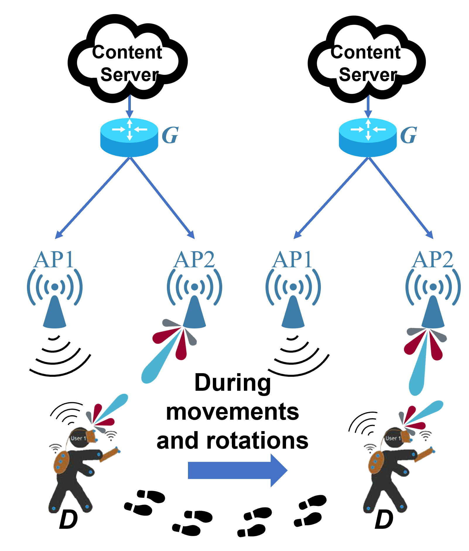
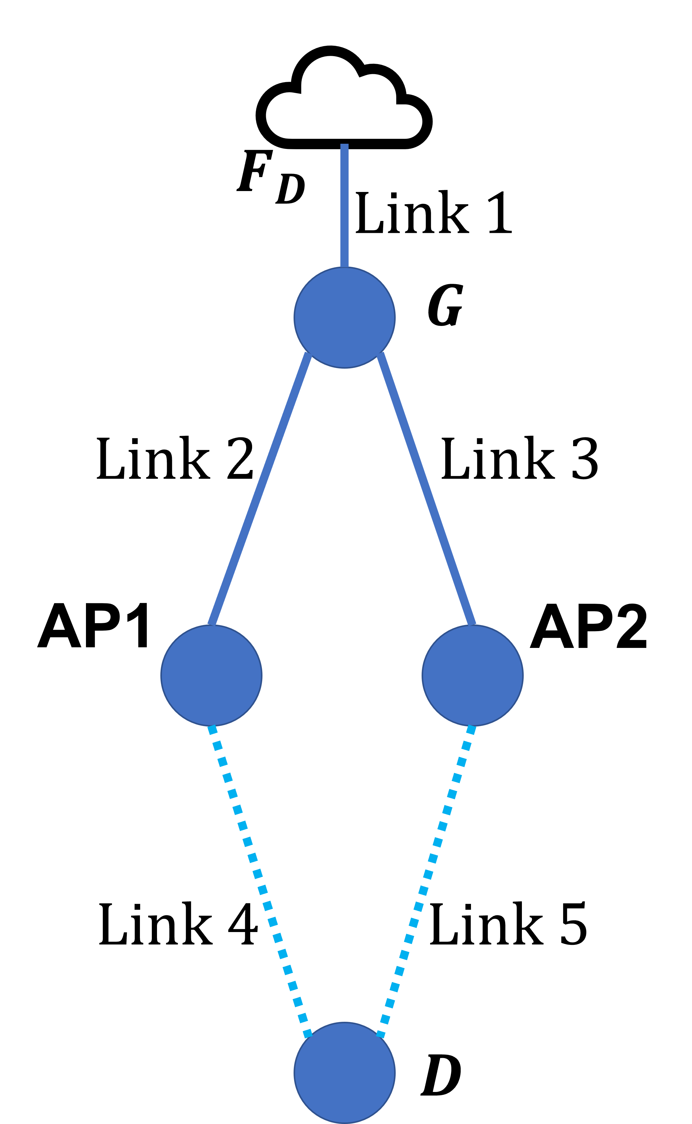
For simplicity of presentation, consider a simple topology formed by an immersive content server: a network gateway , one sub-6G AP (AP1), one mmWave AP (AP2), and a mobile device (e.g., AR/VR headset) (see Fig. 1(a) and 1(b)). Assume that the mobile device moves in a small geographic area in the vicinity of these two APs as a part of the immersive experience. In the immersive experience, the user moves from one place to another. During this process, the user induces changes in pose, location and direction, which result in mmWave channel quality variations.
Gateway is on the route from the content server to the device . It forwards the packets belonging to the traffic flows that are associated with the delivery of the immersive content. Specifically, the traffic flows may be comprised of multiple TCP flows, multiple flows can help achieve higher throughput because it is easier to deal with slower growth in the congestion window of each flow after packet losses or reordering effects. Aiming to provide low-latency and high TCP throughput to the mobile device, when the network gateway receives packets of , it forwards them to the two APs. Device is simultaneously connected to both APs. It may receive packets from both APs at the same time. COTAG is a network layer solution that complements the different strategies implemented at the physical and link layers. The key aspect of the proposed scheme is that the forwarding of the packets at and the two APs does not occur in the traditional fashion. Instead, they forward using concepts of coded forwarding, coded taking, and giving as described below.
III-B COTAG Illustration
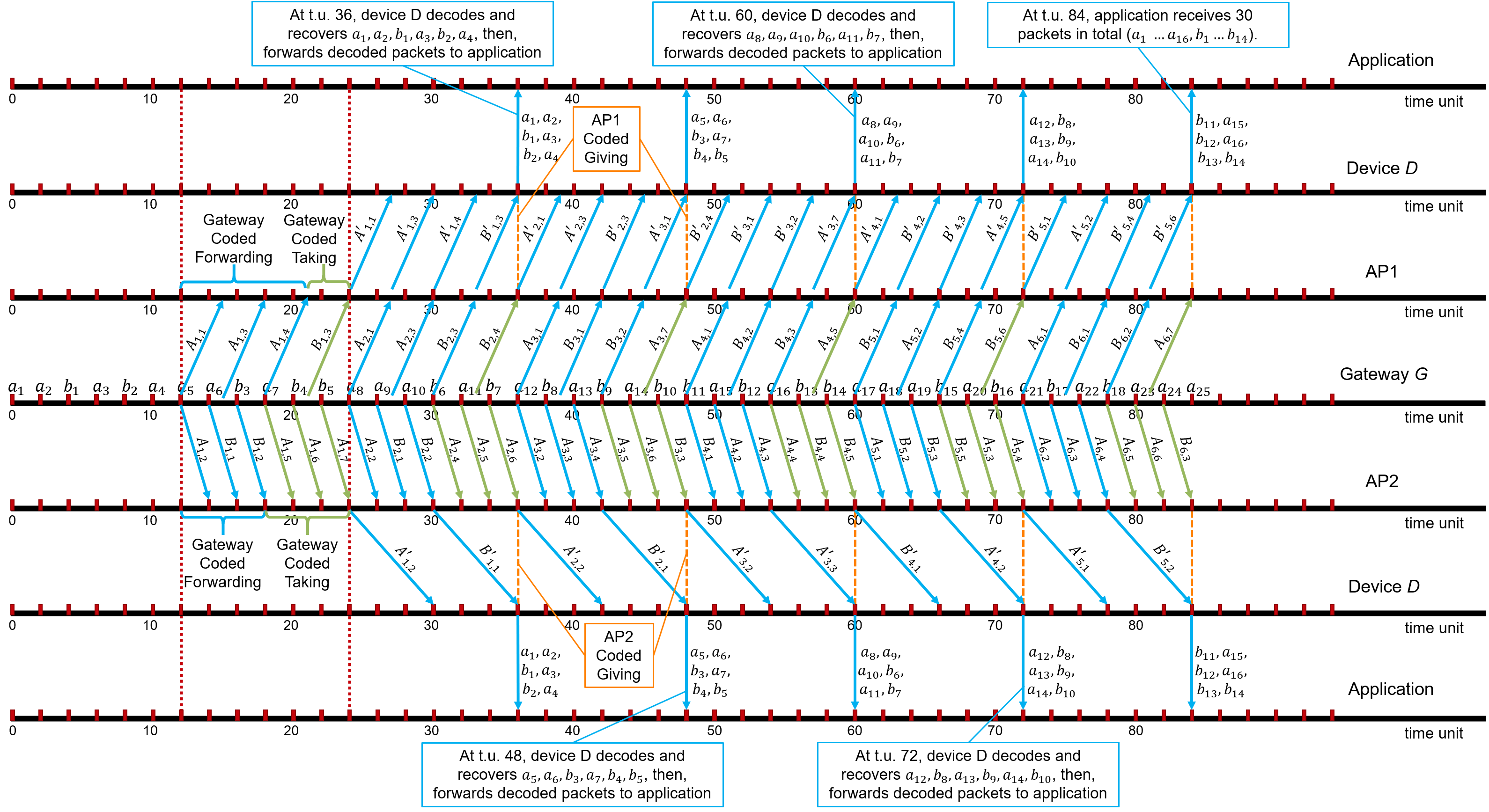
Fig. 2 shows how sequenced packets at gateway are delivered to the application using COTAG. For simplicity of explanation, this example assumes that , AP1, AP2, and are tightly synchronized. In reality, as detailed in later sections of this paper, the COTAG is self-clocking and synchronization between the nodes is not needed. COTAG introduces three concepts: Coded Forwarding, Coded Taking, and Giving.
Coded Forwarding: Instead of forwarding packets in its queue, each node (, AP1, and AP2) forwards “network coded” packets, which are linear combinations of a cohort of packets from the same TCP flow. To create a cohort of packets, COTAG a priori selects a “buffering time” denoted by . In Fig. 2, the value of is 12. All packets arriving at in the interval , = 1, 2, …, are buffered until time . These packets form cohort “”. In Fig. 2, all packets that arrive at in the interval [0, 12) form cohort 1. They are not forwarded until time 12. Similarly, packets which arrive at in the interval [12, 24) form cohort 2, and so on. At time 12, starts forwarding packets from cohort 1. The first packet in the queue from cohort 1 is . Therefore, linearly combines all cohort 1 packets from the “” flow (, , , and ) to generate a network coded packet and forwards it to AP1. The second packet in the queue from cohort 1 is . Therefore, once again generates a network coded packet by combining , , , and and forwards it to AP2. After is transmitted, the third packet in the queue is . Therefore, linearly combines and and forwards it to AP2. Gateway proceeds similarly until all packets in the queue have been considered or it is time for the next cohort. Similarly, nodes AP1 and AP2 also buffer incoming packets and forward linearly coded packets from the same cohort.
Coded Taking: , AP1, and AP2 are not done with forwarding packets in a cohort after they have been through the buffer once during the time interval. For example, at time 18, is done considering all the six packets in cohort 1 once. However, the time allocated for transmitting cohort 1 does not end till time 24. Between time 18 and 24, forwards redundant packets. Specifically, it reconsiders the first, second, third, and so on packets in cohort 1, generates appropriate network coded packets and forwards them until either the time expires or a specified redundancy limit is achieved. Since is the first packet in this cohort, at time 18, forwards , which is a linear combination of , , , and . In this example, for cohort 1, , , , and are redundant packets; there are six packets in cohort 1 but forwarded a total of 10 packets for cohort 1 to AP1 and AP2. AP1 and AP2 also follow the same strategy, although the example does not show this situation.
Giving: Sometimes, depending on the link bandwidth and the number of packets in the cohort, , AP1, and AP2 may not have adequate time to even consider all packets in the cohort at least once. In this case, “Giving” is invoked. Unlike in conventional forwarding, , AP1, and AP2 does not forward all packets that are queued. If the time for a cohort runs out before all the packets are forwarded, the nodes simply discard the remaining packets and transition to handling the next cohort. For example, AP2 receives six packets of cohort 1 in the interval [12, 24). However, due to low data rate of the mmWave link between AP2 and , AP2 is only able to forward two of these packets, in a network coded fashion, in the interval [24, 36). At time 36, AP2 discards all cohort 1 packets and starts forwarding packets from cohort 2.
III-C COTAG Mechanism
Specifically, the proposed scheme COTAG has a parameter that represents the scheme interval. The COTAG scheme applies interval parameter to arrange arrived packets in cohorts for Coded Forwarding, Coded Taking and Giving. All packets of that arrive at in the time interval , are queued and forwarded only in the interval , for integer . Let us refer to the packets of which arrive in the time interval , as cohort packets.
In time interval :
Operations at Gateway : Forwarding at in the interval occurs in the following way with the description in Algorithm. 1.
-
•
Coded Forwarding. All cohort packets are forwarded to the two APs in accordance to scheduling policy; some are forwarded to one AP, while the others are forwarded the other AP. However, they are not forwarded in the conventional way. Instead, when the scheduler is ready to forward a packet from , it forwards a random linear combination, i.e.. network coding [17, 18], of all cohort in the queue. Before forwarding, the packet header is modified to indicate that it is from cohort and it is also tagged “high priority”. It proceeds in this fashion either until all cohort packets have been forwarded once or until the interval expires. Cohort packets are not discarded from the queue immediately after forwarding; instead they are used for coded taking.
-
•
Coded Taking. If additional time is available until , also transmits redundant packets to both APs in accordance with scheduling policy. Note that, this additional time is present when the sum of the bandwidth available for from to the two APs exceeds the current TCP throughput for , a common occurrence when the bottleneck is at the mmWave links. The redundant packets are obtained by random linear combination of cohort packets. Prior to forwarding, the packet header is modified to indicate that it is from cohort . These packets are also tagged as “low priority”. At time , all cohort packets are discarded.
When a packet in arrives on incoming link :
Operations at Each AP: Algorithm. 2 describes the operations at each AP. Cohort packets are queued and not forwarded until the first cohort packet arrives. Forwarding occurs with following mechanism.
-
•
Giving. Forwarding of cohort packets occurs immediately after the arrival of the first cohort packet and only until the first cohort packet. As soon as the first cohort packet arrives, the remaining cohort packets in the queue are discarded, even if they were never forwarded. This important aspect of the proposed schemed is called Giving, because unlike conventional routers, it may give away packets without forwarding when bandwidth is not available.
-
•
Coded Forwarding. High priority cohort packets are forwarded to mobile device over the mmWave link in accordance with scheduling policy.
-
•
Coded Taking. If additional time is available until first cohort packet arrives, AP also forwards linear combination of cohort packets in the queue.
When a packet in arrives on incoming link :
Operations at Mobile Device : Algorithm. 3 describes “Algorithm Mobile Device”, the operations executed by the mobile device . Similar to , the mobile device also follows the label value of the network encoded packets of to determine which packets to decode. The mobile device decodes packets with label when each incoming link has received a packet in with label greater than , the smallest unprocessed label in buffer. If packets are successfully decoded, the unencoded packets are forwarded to the application layer for immersive content streaming. Otherwise, undecoded packets are discarded.
IV Evaluation
The performance of COTAG is evaluated using a network simulator. The network simulator uses measurements from a wearable VR setup for link bandwidth fluctuations. The setup measures the link bandwidth fluctuations caused by changes in user poses, locations, and directions while participating in an immersive experience on an Oculus Quest 2 headset. Although the Oculus Quest 2 headset does not support IEEE 802.11ay mmWave wireless link, the wearable setup includes 802.11ay devices deployed to capture the effects of user movements on the mmWave link bandwidth. The simulations explore the impact of user movements on transport layer performance during the immersive VR experience. We compare the performances of MuSher and COTAG for different network delays and packet error rates (PER) in the network simulator.
IV-A Experimental Setup
Wearable real-time VR mmWave channel measurement system: We first build the wearable mmWave link system to measure the mmWave channel capacity at real time during the use of VR headset.
IV-A1 VR scenario setup
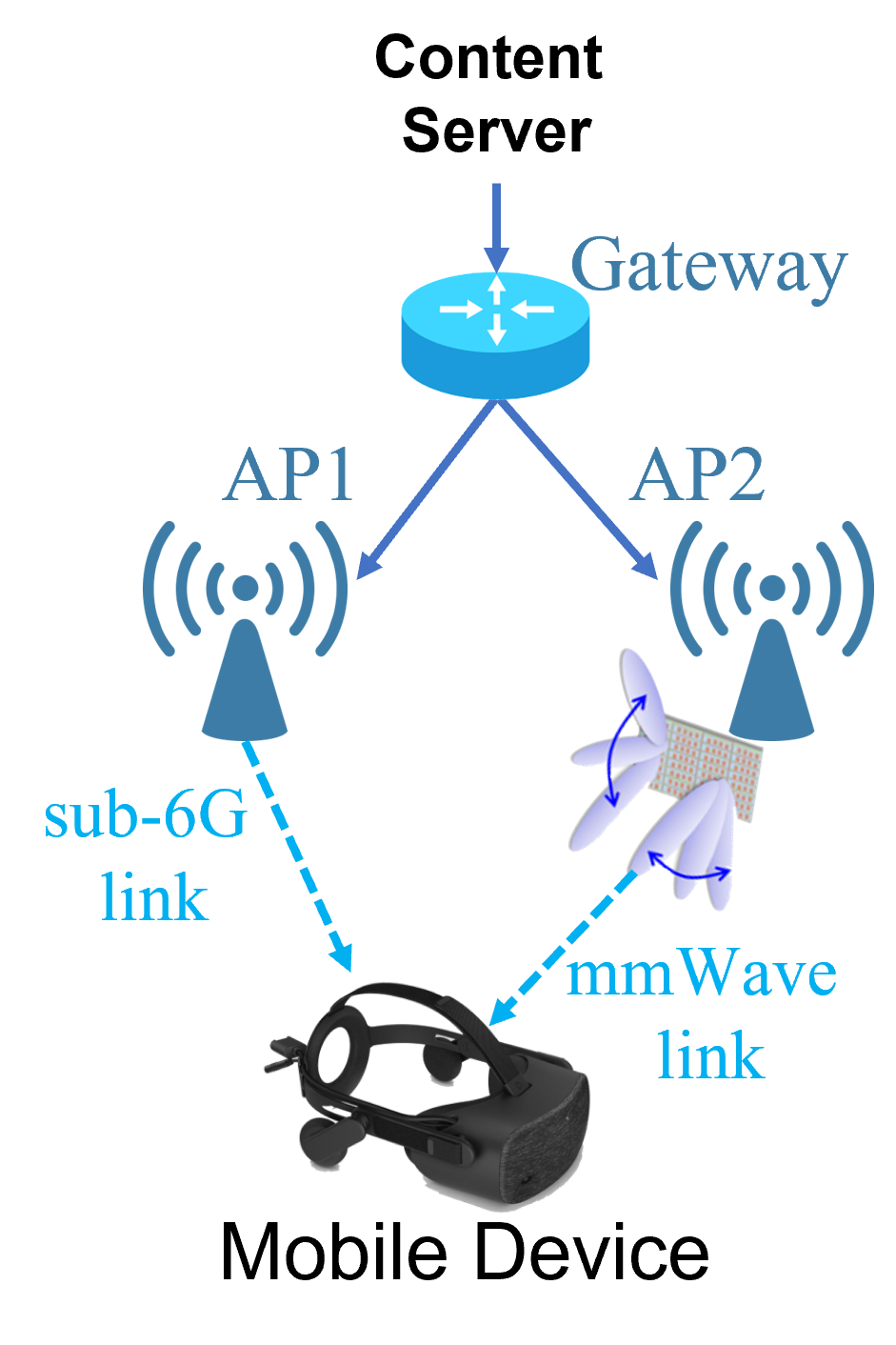
The dual connectivity scenario of mmWave network simulations are shown in Fig. 3(a). This dual connectivity involves one sub-6G connection and one mmWave connection with modern beamforming techniques. These two connections are supported by two different APs, which are connected to the same gateway. The mobile device associates with these two connections to establish dual link connectivity and receives packets from both mmWave and sub-6G APs simultaneously. Since the user movements are fairly small, the sub-6G connection seems to provide a relatively stable channel bandwidth.
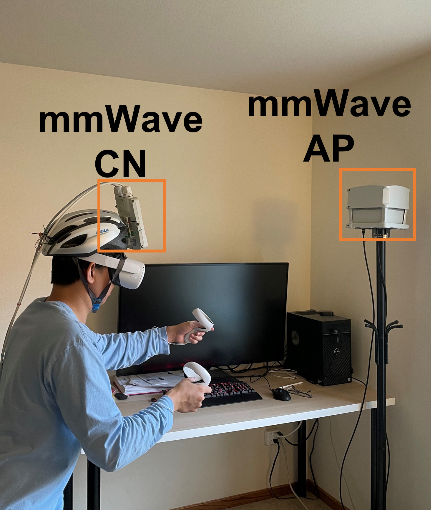
Fig. 3(b) shows a picture of a user in an immersive VR experience. The setup augments Oculus Quest 2 headset with additional mmWave devices because the current headset does not support mmWave connections. The mmWave link channel quality fluctuations are obtained from measurements while the user is in the immersive experience. The user wears both the VR headset and the mmWave client node (CN) on the head and the mmWave channel capacity between the AP and the CN is measured in real time while the user is using VR applications. To measure the network-layer link bandwidth fluctuations in real-time which the user is participating in a VR experience, we use a well-known technique called packet trains [19].
IV-A2 Packet train based measurement of link bandwidths
Packet train is an extension of a concept called packet pair [19]. A packet pair measurement system is comprised of a sender and a receiver. The network route from the sender to the receiver goes through the link whose bandwidth is to be measured. The packet pair technique assumes that desired link has the smallest bandwidth among all the links in the route. The packet pair sender transmits two back-to-back measurement packets. The technique relies on the observation that often these two packets get queued back-to-back waiting for transmission on the desired link and then get transmitted back-to-back on the desired link. When this happens, the spacing between the two packets (called the time dispersion) is inversely proportional to the link bandwidth. Due to different measurement errors, the link bandwidth may not be correctly estimated one packet pair. However, a good estimate can be obtained from repeated packet pair measurements. When the link bandwidth is high, as in the case of mmWave links, the time dispersion is very small and the receiver clock may not be accurate enough to measure time dispersion accurately.
To overcome this problem, one can use a train of measurement packets, instead of a pair. This ideas is illustrated in Fig. 4. One packet train is a group of UDP packets having the same size. As shown in the figure, ideally, all the packets in the train are queued and then later transmitted back-to-back on the mmWave link. Once the receiver receives a packet train, it calculates the bottleneck bandwidth along the path according to the train length and the time dispersion in the bottleneck bandwidth. If is the length of one packet train and the UDP packet size is , then relationship to link bandwidth can be shown to be . The errors in measurement depend on the length of the packet train and the length of each packet in the train. Long packet trains and long packets tend to have smaller errors. However, they also increase the overhead of measurement. Through targeted simulations where one could quantify the errors, we chose the following paramters: = 30 packets, = 1500 Bytes. Since the link bandwidth fluctuates, we chose to repeat the packet train measurement once every 10 ms. Note that, overhead of this measurement is only 36 Mbps for an approximately 1 Gbps link. The trace of channel measurements from this setup was input to simulations in the form of data rates.

IV-B Performance Evaluation
We set different network delays and packet error rates (PER) and measure the short-term TCP throughput and latency of MuSher and COTAG during the burst of immersive data transmitting in real mmWave channels. In simulations, TCP-CUBIC [5] is used to assure reliable, sequenced delivery of packets with the packet size of 128 bytes. The channel bandwidth observed at the network layer is set in the form of data rate value and the bandwidth changes according to the packet train measurement interval, which is 10 ms, reflecting the network-layer channel quality with the impacts at MAC and physical layers. Results are shown in Fig. LABEL:ShortTermCompare and LABEL:Time.
V Conclusion
Dual connectivity transmission based on mmWave and sub-6G wireless links is considered for delivering immersive content to AR/VR applications. To better enhance the robustness of dual connectivity transmission on network layer, we propose a COded Taking And Giving (COTAG) scheme in the presence of user movements, rotations and blockages. The simulation results show that considering network latency, packet errors, and link quality unbalance and fluctuations in dual connectivity, when traditional transport layer solutions are affected, COTAG can enhance TCP’s short-term throughput and latency for short data bursts.
Acknowledgments
This work was partially supported by National Science Foundation grant CNS 1703389, U.S.A and by grant MOST 108-2221-E-011-058-MY3 of the Ministry of Science and Technology, Taiwan, R.O.C.
References
- [1] S. Sun, T. Rappaport, M. Shafi, P. Tang, J. Zhang, and P. Smith, “Propagation Models and Performance Evaluation for 5G Millimeter-Wave Bands,” IEEE Transactions on Vehicular Technology, vol. 67, no. 9, pp. 8422–8439, Sep. 2018.
- [2] T. S. Rappaport, Y. Xing, G. R. MacCartney, A. F. Molisch, E. Mellios, and J. Zhang, “Overview of Millimeter Wave Communications for Fifth-Generation (5G) Wireless Networks–With a Focus on Propagation Models,” IEEE Transactions on Antennas and Propagation, vol. 65, no. 12, pp. 6213–6230, Dec. 2017.
- [3] P. Popovski, Č. Stefanović, J. J. Nielsen, E. de Carvalho, M. Angjelichinoski, K. F. Trillingsgaard, and A. Bana, “Wireless Access in Ultra-Reliable Low-Latency Communication (URLLC),” IEEE Transactions on Communications, vol. 67, no. 8, pp. 5783–5801, Aug. 2019.
- [4] S. Floyd and T. Henderson, “The NewReno Modification to TCP’s Fast Recovery Algorithm,” RFC Editor, RFC 2582, Apr. 1999.
- [5] S. Ha, I. Rhee, and L. Xu, “CUBIC: A New TCP-friendly High-speed TCP Variant,” ACM SIGOPS Operating Systems Review, vol. 42, no. 5, pp. 64–74, Jul. 2008.
- [6] K. Tan, J. Song, Q. Zhang, and M. Sridharan, “A Compound TCP Approach for High-speed and Long Distance Networks,” in Proceedings of International Conference on Computer Communications (INFOCOM), Apr. 2006, pp. 1–12.
- [7] D. Scholz, B. Jaeger, L. Schwaighofer, D. Raumer, F. Geyer, and G. Carle, “Towards a Deeper Understanding of TCP BBR Congestion Control,” in 2018 IFIP Networking Conference (IFIP Networking) and Workshops, May 2018, pp. 1–9.
- [8] H. Haile, K.-J. Grinnemo, S. Ferlin, P. Hurtig, and A. Brunstrom, “End-to-end congestion control approaches for high throughput and low delay in 4G/5G cellular networks,” Computer Networks, vol. 186, p. 107692, Feb. 2021.
- [9] R. Barik, M. Welzl, S. Ferlin, and O. Alay, “LISA: A Linked Slow-start Algorithm for MPTCP,” in 2016 IEEE International Conference on Communications (ICC), May 2016, pp. 1–7.
- [10] M. Z. Michele Polese, Rittwik Jana, “TCP in 5G mmWave Networks: Link Level Retransmissions and MP-TCP,” in IEEE INFOCOM WKSHPS, Mar. 2017, pp. 1–6.
- [11] S. K. Saha, S. Aggarwal, R. Pathak, D. Koutsonikolas, and J. Widmer, “MuSher: An Agile Multipath-TCP Scheduler for Dual-Band 802.11ad/ac Wireless LANs,” in The 25th Annual International Conference on Mobile Computing and Networking, Oct. 2019, pp. 1–16.
- [12] C.-Y. Huang and P. Ramanathan, “Network Layer Support for Gigabit TCP Flows in Wireless Mesh Networks,” IEEE Transactions on Mobile Computing, vol. 14, no. 10, pp. 2073–2085, Oct. 2015.
- [13] S. Sur, I. Pefkianakis, X. Zhang, and K.-H. Kim, “WiFi-Assisted 60 GHz Wireless Networks,” in Proceedings of the Annual International Conference on Mobile Computing and Networking, Oct. 2017, pp. 28–41.
- [14] G. Yang, M. Xiao, M. Alam, and Y. Huang, “Low-Latency Heterogeneous Networks with Millimeter-Wave Communications,” IEEE Communications Magazine, vol. 56, no. 6, pp. 124–129, Jun. 2018.
- [15] Z. Li, Y. Shu, G. Ananthanarayanan, L. Shangguan, K. Jamieson, and V. Bahl, “Spider: Next generation Live Video Analytics over Millimeter-Wave Networks,” Microsoft, Tech. Rep. MSR-TR-2020-17, May 2020.
- [16] L. Dai, B. Wang, Y. Yuan, S. Han, I. Chih-lin, and Z. Wang, “Non-orthogonal multiple access for 5G: solutions, challenges, opportunities, and future research trends,” IEEE Communications Magazine, vol. 53, no. 9, pp. 74–81, Sep. 2015.
- [17] D. Vukobratovic, A. Tassi, S. Delic, and C. Khirallah, “Random Linear Network Coding for 5G Mobile Video Delivery,” Information, vol. 9, no. 4, Apr. 2018.
- [18] S.-Y. R. Li, R. W. Yeung, and N. Cai, “Linear Network Coding,” IEEE Transactions on Information Theory, vol. 49, no. 2, pp. 371–381, Feb 2003.
- [19] C. Dovrolis, P. Ramanathan, and D. Moore, “Packet Dispersion Techniques and Capacity Estimation,” IEEE/ACM Transactions on Networking, vol. 12, pp. 963–977, Dec. 2004.