Application of Flexible Numerology to Blockage Mitigation in 5G-mmWave Networks
Abstract
The 5G New Radio (NR) standard for wireless communications supports the millimetre-wave (mmWave) spectrum to yield unprecedented improvement of the access network capacity. However, intermittent blockages in the mmWave signal may degrade the system performance and lead to the under-utilisation of the allocated resources. To circumvent this problem, the transmission slot-time shall be adjusted according to the blockage condition, avoiding the resource under-utilisation. In this paper, we propose that the 5G NR flexible numerology should be applied to adapt the slot-time in order to mitigate the blockage effects. We validate this claim by analysing the expected data rate of a mmWave system, under a range of blockage scenarios. We show that different blockage scenarios may require different numerologies to produce best performance, and that the correct choice of numerology may improve this performance by as much as hundreds of Mbps. Our results carry insights important for the design of blockage-aware scheduling mechanisms for 5G.
Index Terms:
millimetre-wave networks, self-body blockage, flexible numerology, performance analysis, blockage mitigation.I Introduction
The fifth-generation (5G) of mobile networks is being developed to boost the available mobile speeds to multi-Gbps, and, consequently, provide support for the increasing user traffic demands [1]. To achieve this goal, 5G networks will use the wide bandwidths available in mmWave (mmWave) frequencies. The challenge is that ordinary objects (e.g., human bodies, furniture) that are “transparent” to signals transmitted over microwave frequencies become blockages when the same signals are transmitted over mmWave.
Blockages in mmWave signal propagation are related to severe attenuation of the signal power (in certain cases, the blockage may add as much as 40 dB of attenuation [2]), which can lead to radio link failures and consequent disconnection in the communication. This issue has mostly been addressed in the literature to date by deployment strategies that allow the network to exploit spatial macro-diversity, i.e., increasing the communication robustness by enabling the user to receive a signal from distinct points in space. These deployment strategies include: reflective surfaces [3], relay nodes [4], dense networks [5], ceiling-mounted AP [6], and movable AP [7] that can position themselves in a way that increases the likelihood of having an AP operating in LOS (LOS). In order to achieve spatial macro-diversity, the MAC (MAC) layer mechanisms should properly coordinate the network nodes and allocate the transmission resources (e.g., time, frequency, space) according to the blockage condition. Yet, as we show in our numerical results, the intermittency of blockage events may cause system performance degradation and lead to resource under-utilisation if a fixed TTI (TTI) is considered.
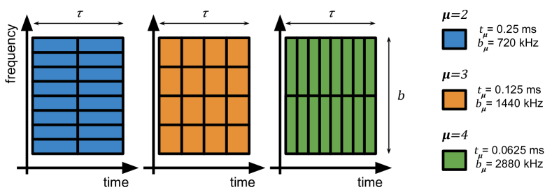
In this paper, we consider adaptable transmission times for blockage mitigation, using the flexible TTI proposed for the 5G NR (NR). The ability of TTI adjustment is enabled by the 5G NR access technology. It works with a flexible OFDM (OFDM) transmission frame system, in which the configuration of TTI, i.e., SCS (SCS) and CP (CP), is flexible, as illustrated in Figure 1. According to the 5G terminology [8], such configuration is referred to as the flexible numerology and the supported numerologies are listed in Table I. Originally flexible numerology was introduced to enable service-level differentiation, i.e., network slicing for different 5G use cases [9].
Herein, we propose an alternative application for flexible numerology. Our claim is that different numerologies will fare better under blockage conditions, and hence may be used to improve the mmWave user performance. We verify our claim by analysing the mmWave link performance using the numerologies available for 5G mmWave systems, under a range of blockage scenarios, defined and empirically-validated in [10]. Our results show that there is a trade-off between the high transmission efficiency, achieved with longer TTI, and the high probability of LOS transmission, achieved using shorter TTI. In consequence, the same numerology used for two different blockage scenarios (office and car-park) leads to opposing conclusions about the system performance, and that the correct choice of numerology may improve this performance by as much as hundreds of Mbps. Effectively, we identify conditions under which it may be favourable to use a given numerology, which shall provide insights important for the design of blockage-aware scheduling mechanisms for 5G.
The rest of the paper is organised as follows. In Section II, we present the state-of-the-art and how our work goes beyond it. In Section III, we describe our system model. In Section IV, we describe our performance metric. In Section V we analyse the link performance comparing the numerologies and the blockage conditions. Finally, we draw our conclusions in Section VI.
| TTI [ms] | CP length [us] | Bandwidth [kHz] | |
| 0 | 1 | 4.690 | 180 |
| 1 | 0.5 | 2.345 | 360 |
| 2* | 0.25 | 1.172 | 720 |
| 3* | 0.125 | 0.586 | 1440 |
| 4* | 0.0625 | 0.293 | 2880 |
| * 5G NR Rel-15 in sub-6 GHz bands can only use numerology, | |||
| while in mmWave bands, only [11]. | |||
II Related Work
The literature on blockage mitigation in mmWave communication is mostly focused on techniques that rely on spatial macro-diversity. Such techniques allow the transmitter to find an alternative physical path for the mmWave signal when the primary LOS path fails due to a blockage event. The main techniques considered are: (i) reflectors: usage of surfaces made of materials that reflect the mmWave signal to cover an obstructed spot through a NLOS (NLOS) path [12, 13]; (ii) relays: forwarding the transmission to a relay node that has a LOS path with the UE (UE) [14, 15]; (iii) movable: moving the AP location during the transmission to a position where there is a LOS path [16]; (iv) multi-connectivity: associating the UE with multiple AP, so the UE can have a LOS path served by a backup AP [17, 18].
It is the responsibility of the MAC layer to coordinate the extra communication nodes (e.g., relay nodes, neighbour AP), and provide a smooth handover between the AP, relays, or reflectors when the mmWave signal power fades due to blockage [19, 20, 21, 22]. However, the intermittent blockages together with fixed TTI may lead to poor utilisation of the transmission resources. Therefore, to avoid this under-utilisation, we propose the application of flexible numerology to mitigate blockage effects through MAC layer transmission time adaptation.
In state-of-the-art flexible numerology has been applied to improve the network latency where the TTI is optimised according to a latency deadline restriction [23] and according to the traffic pattern [24]. Also, it has been applied to improve the frame spectral efficiency when multiplexing different types of services, e.g., eMBB (eMBB) and URLLC (URLLC) [25, 26].
III System Model
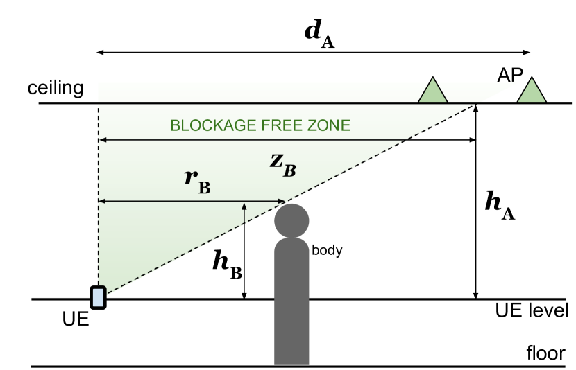
We consider a single cell, with an AP installed on the ceiling or a lamppost, transmitting a 5G OFDM frame to a UE at a distance in the horizontal plane. The AP is installed at a height above the UE level, as illustrated in Figure 2(a). This setup shall generalise over the two deployment scenarios considered in [10], but is also in-line with the 3GPP-defined scenarios for 5G mmWave system evaluation [27]: indoor office with ceiling-mounted access points and outdoor car-park with lamppost mounted access points.
We assume the resource allocation decision in the AP is made every ms, which we refer to as the SI (SI). For ease of exposure, we consider the link performance as experienced by a single user, attached to a single cell. The cell’s bandwidth is and can be filled using flexible numerology with resource blocks of bandwidth and TTI , as illustrated in Figure 1.
III-A Blockage Probability Model
Whether or not the LOS path to the UE is blocked during a slot within the SI depends on the blockage probability. We define the blockage probability as the probability of a slot being blocked during a given interval. This probability is given by the probability of self-body blockage as in [6]:
| (1) |
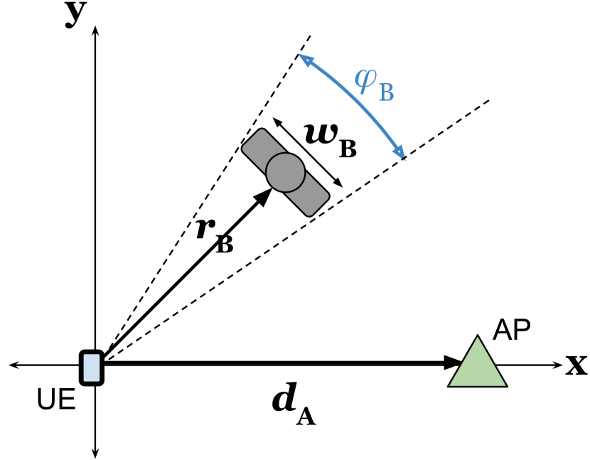
where is the body width, is the distance between the body and the UE, and is the distance between the UE level and the top of the body, and is the self-body blockage free zone radius, as illustrated in Figure 2.
III-B Signal-to-Noise Ratio
For modelling of the mmWave signal propagation, we consider the experimentally-validated channel model proposed in [10]. The model consists of the path loss and the composite Gamma-Nakagami-m fading, whose parameters take one of two values depending on whether the user body blocks the LOS path, meaning that the model parameters change with the random blockage state. The fading and path-loss coefficients for that model were estimated from the experimental data collected for a mmWave AP operating at 60 GHz in [10].
We define the set of the two possible blockage states as . Hence, given the blockage state , we can define the path loss as , where is the Euclidean distance from the AP to the UE, is the path loss at one metre distance under free space propagation, and is the attenuation exponent.
Instead of treating each fading component individually, we consider the fading gain as a single random variable with a composite fading distribution, as obtained in [28]. This approach allows us to define the complementary cumulative distribution function (ccdf) of the SNR in (4) based on the formula in [28, (15)] as follows:
| (2) |
where is the SNR without the fading component, the variable is the Nakagami-m fading parameter, () are the Gamma shadowing parameters, is the modified Bessel function of the second kind of order , and the used constants are:
| (3) |
where is the Gamma function.
Thus, we define the signal-to-noise ratio (SNR) , conditioned on , as:
| (4) |
where is the transmit power, is the noise power, and is the fading gain.
III-C Transmission Efficiency and Slot Aggregation Efficiency
We define the transmission efficiency of a resource block of type as the decrease in the spectral efficiency for shorter TTI due to inter-symbol interference caused by shorter CP [29]. The longer the TTI, the greater the transmission efficiency, i.e., for all .
We also define the slot aggregation efficiency as the ratio between the number of symbols that are used for data transmission and the total number of symbols.
IV Performance Analysis
We evaluate the performance of our system in terms of the expected data rate. To calculate it, we consider the probability of blockage, the spectral efficiency of the channel, the transmission efficiency of each resource block, and the slot aggregation efficiency.
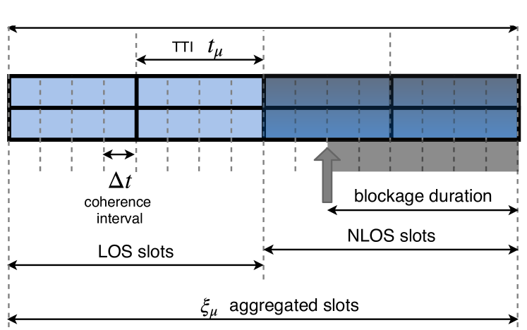
We consider that the TTI is a multiple of (see Figure 3), which is the blockage “coherence” interval. Within this interval, the blockage event has probability as described in (1) and is independent of the previous interval, but once the first blockage event happens, we assume that all the following slots within the SI are also blocked111For 5G NR it has been shown in [30] that the body blockage duration can be in the order of 100 ms (due to low mobility of pedestrians) versus the 10 ms duration frames.. Consequently, a slot, that contains coherence intervals (), is transmitted in LOS if no blockage has occurred in previous slots and in each of its own coherence intervals. Thus, the probability of the -th slot being in LOS is:
| (5) |
The spectral efficiency can be expressed as , and has only non-negative values. Hence, the expected value conditioned to the blockage state of the -th slot can be represented by this integral which can be efficiently computed numerically:
| (6) |
where is ccdf of the SNR defined in (2). Thus, the expected spectral efficiency with respect to the blockage state of the -th slot is:
| (7) |
where (a) comes from using (1) and from the fact that the channel is constant with the same blockage state.
Finally, the expected data rate using the numerology () of a slot aggregation of slots is given by the expectation of the sum of the spectral efficiency of each slot multiplied by the frame bandwidth and the transmission and slot aggregation efficiencies:
| (8) |
| (9) |
V Numerical Results
In this section, we show the benefits of the application of the flexible numerology to blockage mitigation in 5G NR mmWave systems. We compare the results for three types of resource blocks supported by mmWave NR (i.e., according to 5G NR Rel-15 [8]), under different blockage scenarios.
We consider two blockage scenarios: a UE held in a pocket ( cm, UE in pocket), and a UE operated with the hand ( cm, UE in hand). The UE in pocket scenario is a severe blockage condition where the body is obstructing half of the “angle-of-view”, thus, the probability of blockage is . The UE in hand scenario is a common blockage condition where the user is, for example, operating an app in the mobile phone, and the body obstructs a smaller angle than in the UE in pocket scenario. We consider two environments: an indoor open office and an outdoor car park. This setup reflects the scenarios and environments characterised in [10], for which coefficients of the fading and path loss models we use were estimated. These coefficients are listed on the left side of Table II (based on [10, Table I]).
We assume that the transmission efficiency decreases by 5% with each increment in the numerology (i.e., , and ). Accurate values for the numerology-dependent transmission efficiency can be obtained following the calculations presented in [29]. We assume that the slot structure is as described in [31], where each slot consists of 14 symbols. In a slot aggregation of slots, the two first symbols are used for downlink and uplink control, the third is used for demodulation reference signal, and the rest of the symbols is for data. Thus, the slot aggregation efficiency is . We set the frame bandwidth as 100 MHz [8] and we evaluate the performance with the SI ms (unless specified otherwise), as in the legacy LTE scheduling. For our analysis, we set ms as the shortest TTI among the numerologies considered. All other fixed system parameters are shown in Table II (right side).
| Channel Model | System Model | ||||||||||||
| Environment | Path Loss | Shadowing | Small-Scale Fading | Transmit Power | 20 dBm | ||||||||
| LOS | NLOS | LOS | NLOS | LOS | NLOS | Noise Density | -174 dBm/Hz | ||||||
| (dB) | (dB) | Body Width | 40 cm | ||||||||||
| Office | 1.18 | 45.1 | 1.07 | 57.4 | 7.01 | 0.15 | 5.77 | 0.20 | 2.64 | 2.35 | Body Height* | 40 cm | |
| Car Park | 1.53 | 48.7 | 1.98 | 88.8 | 10.30 | 0.11 | 5.11 | 0.23 | 8.50 | 2.74 | AP Height* | 5 m | |
| * with respect to the UE level | |||||||||||||
V-A Environment and Blockage Impact
In this subsection, we evaluate the impact of two environments (an office and a car park), with distinct channel characteristics, and two blockage scenarios (UE in hand and UE in pocket) on the expected data rate of mmWave communication. We also compare the scenarios where the UE is close to the AP ( m) and where the UE is far from the AP ( m). The results are shown in Figure 4.
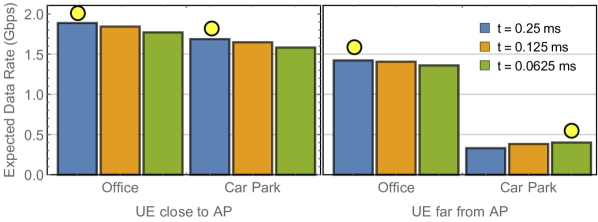
From the left side of Figure 4(a), we see that the expected data rate is higher when using a TTI of ms (blue bar), compared to other TTIs, for a user close to the AP and operating the UE with the hand. In this case, the blockage probability is very low, allowing for high transmission efficiency of the resource block with long slot duration to have a more significant impact on the data rate than the blockage. On the right-hand side of that same figure, we observe a decrease in the expected data rate because of the dual-effect of increased path loss and blockage probability for a user further away from the AP. The car park environment suffers more from blockages compared to the office environment as there is less power in the NLOS signal, likely due to lack of reflecting/scattering environment. Thus, short TTI ( ms, green bar) mitigates the blockage effects by increasing the expected number of slots in LOS and, then, yields better performance in the car park environment.
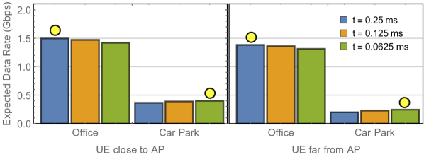
From Figure 4(b), we note that the expected data rate has similar trends when we vary the distance between the UE and the AP, as the considered range of distances have little effect on the blockage probability for the UE in the pocket. We see that the user in the office environment achieves highest expected data rate using TTI ms, and in the car park environment, the user achieves highest expected data rate using TTI ms in both cases (UE close to AP and far from AP) of the UE in pocket scenario.
V-B Scheduling Interval Impact
In LTE networks, the scheduler makes the allocation decision every TTI, which has a fixed duration of 1 ms, and the decision is valid until the next TTI [32]. The 5G NR allows slot aggregation, in which the aggregation duration can span two or more slots to reduce control overhead. Hence, the scheduling decision interval is no longer fixed and can vary with the slot aggregation size. Here, we evaluate the impact of the aggregation overhead reduction by comparing the SIs ms (short SI)222A SI of ms allows to allocate at least one of the longest TTI ( ms) considered. and ms (long SI)333Any longer SI between 5 and 10 ms leads to similar results.. The results considering the car park environment are shown in Figure 5.
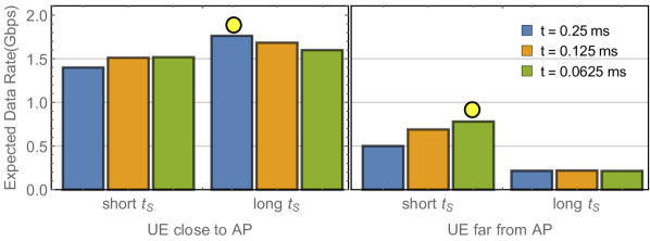
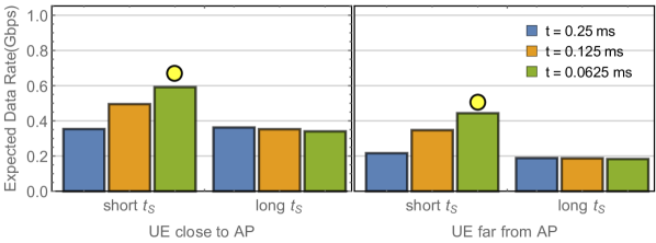
From Figure 5, we observe that, in most cases, a short SI achieves better performance with short TTI (green bar) compared to long TTI (blue bar). The only exception, as we see from the left side of Figure 5(a), is the scenario of a user close to the AP operating the UE with the hand. In this scenario, the best performance is achieved by long SI with long TTI. This is because the effects of increased transmission efficiency (long TTI) and reduced overhead (long SI) have a higher impact on the expected data rate than the low blockage probability. In other cases, i.e., UE far from AP in UE in hand scenario and both cases in UE in pocket scenario (see Figure 5(b)), the blockage probability is high and has more impact on the expected data rate than the overhead reduction. Thus, there is no benefit in increasing the SI in those cases.
To sum up, the appropriate combination of numerology and scheduling interval is essential to achieve the best performance. For example, in the cases where the blockage has more significant impact on the expected data rate (e.g., UE far from AP or UE in pocket), the use of short SI with short TTI is recommended to avoid prolonged exposure to blockage interruptions. On the other hand, in the cases where the blockage has less impact (e.g., UE close to AP), the use of long SI with long TTI is recommended to take advantage of the reduced overhead and the high transmission efficiency.
VI Conclusion
In this paper, we proposed that 5G NR flexible numerology be used to mitigate the negative effects of body blockage in 5G mmWave systems. We presented an analytical framework that allowed us to show and understand the benefits of our proposed application of flexible numerology. We showed that different blockage conditions require different combinations of numerology and slot aggregation to achieve the best performance, as presented in Table III. The effectiveness of flexible numerology in mmWave blockage scenarios is a consequence of the trade-off between the high transmission efficiency, achieved with long TTI, and the high probability of LOS transmission, achieved using short TTI.
| Office | Car Park | |||
| Environment | UE close | UE far | UE close | UE far |
| to AP | from AP | to AP | from AP | |
| UE in hand | ||||
| UE in pocket | ||||
This work is a stepping stone to further studies on the application of flexible numerology to blockage mitigation in 5G-mmWave networks. Further work is needed to investigate the implications of multiple users or services sharing the frame, as well as how the effectiveness of flexible numerology affects the blockage mitigation via macro-diversity. Nonetheless, the results we have shown thus far should motivate the development of new scheduling algorithms/policies for the 5G NR mmWave frame.
Acknowledgement
This publication has emanated from the research conducted within the scope of NEMO (Enabling Cellular Networks to Exploit Millimetre-wave Opportunities) project financially supported by the Science Foundation Ireland (SFI) under Grant No. 14/US/I3110 and with partial support of the European Regional Development Fund under Grant No. 13/RC/2077. We are thankful to Danny Finn who kindly assisted us with the Wolfram Mathematica® software.
Appendix A
All scripts used to generate the presented results were written in Wolfram Mathematica® and are available in https://github.com/firyaguna/wolfram-flexible-numerology.
References
- [1] “Setting the scene for 5G: opportunities and challenges,” International Telecommunication Union (ITU), Tech. Rep. ITU Thematic Reports, Sep. 2018. [Online]. Available: https://www.itu.int/pub/D-PREF-BB.5G_01-2018
- [2] G. R. Maccartney, T. S. Rappaport, and S. Rangan, “Rapid Fading Due to Human Blockage in Pedestrian Crowds at 5G Millimeter-Wave Frequencies,” in 2017 IEEE Global Communications Conference (GLOBECOM), Dec. 2018.
- [3] A. Narayanan, T. V. Sreejith, and R. K. Ganti, “Coverage Analysis in Millimeter Wave Cellular Networks with Reflections,” in 2017 IEEE Global Communications Conference (GLOBECOM), Dec. 2017.
- [4] W. I. Kim, J. S. Song, and S. K. Baek, “Relay-Assisted Handover to Overcome Blockage in Millimeter-Wave Networks,” in 2017 IEEE International Symposium on Personal, Indoor and Mobile Radio Communications (PIMRC), Oct. 2017.
- [5] T. Bai and R. W. Heath, “Coverage and Rate Analysis for Millimeter-Wave Cellular Networks,” IEEE Transactions on Wireless Communications, vol. 14, no. 2, pp. 1100–1114, Feb. 2015.
- [6] F. Firyaguna, J. Kibilda, C. Galiotto, and N. Marchetti, “Coverage and Spectral Efficiency of Indoor mmWave Networks with Ceiling-Mounted Access Points,” in 2017 IEEE Global Communications Conference (GLOBECOM), Dec. 2017.
- [7] M. Gapeyenko et al., “Effects of Blockage in Deploying mmWave Drone Base Stations for 5G Networks and Beyond,” in 2018 IEEE International Conference on Communications Workshops (ICC), May 2018.
- [8] “5G NR; Physical channels and modulation,” 3GPP, Tech. Rep. TS 38.211 V15.3.0, Sep. 2018.
- [9] M. Shafi et al., “5G: A Tutorial Overview of Standards, Trials, Challenges, Deployment, and Practice,” IEEE Journal on Selected Areas in Communications, vol. 35, no. 6, pp. 1201–1221, June 2017.
- [10] S. K. Yoo et al., “Channel Characteristics of Dynamic Off-Body Communications at 60 GHz Under Line-of-Sight (LOS) and Non-LOS Conditions,” IEEE Antennas and Wireless Propagation Letters, vol. 16, pp. 1553–1556, 2017.
- [11] “5G NR; User Equipment (UE) Radio Transmission and Reception; Part 2: Range 2 Standalone,” 3GPP, Tech. Rep. TS 38.101-2 V15.3.0, Oct. 2018.
- [12] S. Kwon and J. Widmer, “Multi-Beam Power Allocation for mmWave Communications under Random Blockage,” in 2018 IEEE Vehicular Technology Conference (VTC), June 2018.
- [13] M. Feng, S. Mao, and T. Jiang, “Dealing with Link Blockage in mmWave Networks: D2D Relaying or Multi-beam Reflection?” in 2017 IEEE International Symposium on Personal, Indoor and Mobile Radio Communications (PIMRC), Oct. 2017.
- [14] S. Wu, R. Atat, N. Mastronarde, and L. Liu, “Coverage Analysis of D2D Relay-Assisted Millimeter-wave Cellular Networks,” in 2017 IEEE Wireless Communications and Networking Conference (WCNC), Mar. 2017.
- [15] Z. Yang et al., “Sense and Deploy: Blockage-aware Deployment of Reliable 60 GHz mmWave WLANs,” in 2018 IEEE 15th International Conference on Mobile Ad Hoc and Sensor Systems (MASS), Oct. 2018.
- [16] J. Bao, D. Sprinz, and H. Li, “Blockage of Millimeter Wave Communications on Rotor UAVs: Demonstration and Mitigation,” in 2017 IEEE Military Communications Conference (MILCOM), Oct. 2017.
- [17] C. Tatino, I. Malanchini, N. Pappas, and D. Yuan, “Maximum Throughput Scheduling for Multi-Connectivity in Millimeter-Wave Networks,” in 2018 16th International Symposium on Modeling and Optimization in Mobile, Ad Hoc, and Wireless Networks (WiOpt), May 2018.
- [18] V. Petrov et al., “Achieving End-to-End Reliability of Mission-Critical Traffic in Softwarized 5G Networks,” IEEE Journal on Selected Areas in Communications, pp. 485–501, Mar. 2018.
- [19] F. B. Tesema et al., “Multiconnectivity for Mobility Robustness in Standalone 5G Ultra Dense Networks with Intrafrequency Cloud Radio Access,” Wireless Communications and Mobile Computing, pp. 1–17, Jan. 2017.
- [20] M. Giordani, M. Mezzavilla, S. Rangan, and M. Zorzi, “Multi-connectivity in 5G mmWave Cellular networks,” in 2016 15th IFIP Mediterranean Ad Hoc Networking Workshop (MEDHOCNET), June 2016.
- [21] V. Petrov et al., “Dynamic Multi-Connectivity Performance in Ultra-Dense Urban mmWave Deployments,” IEEE Journal on Selected Areas in Communications, pp. 2038–2055, Sep. 2017.
- [22] M. Polese et al., “Improved Handover Through Dual Connectivity in 5G mmWave Mobile Networks,” IEEE Journal on Selected Areas in Communications, pp. 2069–2084, Sep. 2017.
- [23] M. Ibrahim and W. Xu, “On Numerology and Capacity of the Self-Contained Frame Structure,” in 2016 IEEE Global Communications Workshops (GLOBECOM), Dec. 2016.
- [24] N. Patriciello, S. Lagen, L. Giupponi, and B. Bojovic, “5G New Radio Numerologies and their Impact on the End-To-End Latency,” in 2018 IEEE 23rd International Workshop on Computer Aided Modeling and Design of Communication Links and Networks (CAMAD), Sep. 2018.
- [25] S. Lagen et al., “Subband Configuration Optimization for Multiplexing of Numerologies in 5G TDD New Radio,” in 2018 IEEE International Symposium on Personal, Indoor and Mobile Radio Communications (PIMRC), Sep. 2018.
- [26] L. You, Q. Liao, N. Pappas, and D. Yuan, “Resource Optimization With Flexible Numerology and Frame Structure for Heterogeneous Services,” IEEE Communications Letters, vol. 22, no. 12, pp. 2579–2582, Dec 2018.
- [27] “5G; Study on Scenarios and Requirements for Next Generation Access Technologies,” 3GPP, Tech. Rep. TR 38.913 V14.2.0, May 2017.
- [28] A. Laourine, M. Alouini, S. Affes, and A. Stephenne, “On the Performance Analysis of Composite Multipath/Shadowing Channels using the G-Distribution,” IEEE Transactions on Communications, vol. 57, no. 4, pp. 1162–1170, Apr. 2009.
- [29] E. Lähetkangas et al., “Achieving Low Latency and Energy Consumption by 5G TDD Mode Optimization,” in 2014 IEEE International Conference on Communications Workshops (ICC), June 2014.
- [30] I. K. Jain, R. Kumar, and S. Panwar, “Driven by Capacity or Blockage? A Millimeter Wave Blockage Analysis,” in 2018 IEEE International Teletraffic Congress (ITC), Sep. 2018.
- [31] P. Mogensen et al., “5G Small Cell Optimized Radio Design,” in 2013 IEEE Global Communications Workshops (GLOBECOM), Dec. 2013.
- [32] F. Capozzi et al., “Downlink Packet Scheduling in LTE Cellular Networks: Key Design Issues and a Survey,” IEEE Communications Surveys Tutorials, vol. 15, no. 2, pp. 678–700, Feb. 2013.