Optimizing micro-tiles in micro-structures as a design paradigm
Abstract
In recent years, new methods have been developed to synthesize complex porous and micro-structured geometry in a variety of ways. In this work, we take these approaches one step further and present these methods as an efficacious design paradigm. Specifically, complex micro-structure geometry can be synthesized while optimizing certain properties such as maximal heat exchange in heat exchangers, or minimal weight under stress specifications.
By being able to adjust the geometry, the topology and/or the material properties of individual tiles in the micro-structure, possibly in a gradual way, a porous object can be synthesized that is optimal with respect to the design specifications. As part of this work, we exemplify this paradigm on a variety of diverse applications.
keywords:
Analysis, heterogeneous materials, topological optimization, porous geometry.1 Introduction
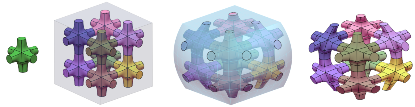
Recently, in [11, 17], methods and algorithms for the precise construction of micro-structures using functional composition [9, 10] were proposed. In that approach, the design of the macro-shape and the micro-structures of a porous geometry are decoupled. A parametric form of a (typically periodic) micro-tile is specified as some combination of curves, surfaces, and/or trivariates while the macro-shape is also specified as a parametric trivariate function . See Figure 1. , the domain of , is populated with tiles , only to compute the final result as the function composition .
|
The approach of [11, 17] has a very simple set of inputs, namely:
-
1.
A micro-tile , as some combination of parametric curves , surfaces and trivariates . Without loss of generality, we assume that is confined to a designated volume, specifically a unit cube. is typically periodic in the sense that the faces are -continuous with respect to , , and may even be -continuous, .
-
2.
A trivariate parametric deformation macro-function .
-
3.
: the dimensions of enumerations in , in of the micro-tile .
Algorithm 1 summarizes this entire process.
Input:
: a micro-tile consisting of curves and/or surfaces and/or
trivariates;
: a trivariate parametric deformation macro-function
;
: the dimensions of the grid enumeration of
tiles in the domain of ;
Output:
: A micro-structure of tiles in
a 3D grid deformed to following the macro-shape of , via
functional compositions, as ;
Algorithm:
|
 |
The result is a precise layout of individual tiles that (continuously) follows the macro shape. However, in , the parametric domain of , all the placed tiles are of the same geometry (up to rigid motion). Clearly, inasmuch as is rarely isometric, can be arbitrarily deformed, which is where this effort begins.
One application that demonstrates these composition based parametric micro-structures is the design of a heat sink [3]. Following the goal of using maximimal surface area to optimize the dissipation of heat while minimizing the volume of material, the synthesis of the geometry can be achieved with relative ease through exploiting hierarchical parametric micro-structures. See Figure 2.
Striving to control the shapes of the tiles in Euclidean space serves as a first motivation for this work. Some general design specifications can be imposed on the object of design in the form of strength, weight, heat or electrical conductivity, etc. One can then consider the geometry and the topology of individual tiles, as well as some interior (materials) properties, as degrees of freedom in some analysis or optimization process, a typical part of a design cycle.
The rest of this work is organized as follows. In Section 2, previous efforts in synthesizing micro-structures are surveyed. Section 3 presents the necessary building block to enable this proposed design paradigm of micro-structures. In Section 4 some examples are considered in a variety of engineering applications. Finally, we conclude in Section 5.
2 Previous work
In recent years, the interest in porous geometry and micro-structures, on one hand, and in heterogeneous materials on the other, has been on the rise. One major motivation for 3D representations stems from the new abilities introduced by additive manufacturing to fabricate such structures [14]. Porous geometry, micro-structures, and heterogeneous materials, all enabled by modern additive manufacturing technologies, are finding applications in a variety of fields from medicine and biology [2], through mechanical and aero-space engineering to electric engineering [25] and material science [1].
The authors in [5] perform optimization of micro-structures towards multi-scale modeling. A set of parameters is identified at the micro-scale level that govern properties of the model like the shape, stress, strain, etc. The finite element method is used in the analysis step. Evolutionary schemes, which are based on genetic algorithms, are used to search for optimal parameter values. Although the NURBs representation is used for the shape of the structures, such an approach lacks precision.
In [7] the authors present a framework for modeling heterogeneous objects using trivariate Bézier patches. The Bézier patches have two sets of coordinates. The first set of three coordinates prescribe the shape of the object, while the rest of the coordinates specify the material composition of the object. While this allows for construction of a wide range of structures with functionally graded materials (FGM), it only admits a single level of details, and is limited only to Bézier trivariates. Modeling of micro-structures, for instance, is beyond the scope of this work.
The authors in [26] adopt principles from stochastic geometry [15] for designing porous artifacts. While such an approach is suitable for designing random micro-structures, for example toward bone tissues, it is less favorable for applications requiring a high level of precision like, for instance, a wing of an aircraft. Also, the approach does not address the question of ensured connectivity of the porous structures. The authors in [30] use Voronoi tessellations to also generate random porous structures of three kinds: porous geometries with intersecting fractures, interconnected tubes and fibers. A set of points is randomly sampled in the space which gives rise to Voronoi tessellations. Offsets are then computed for the edges of the tessellations to generate the three kinds of micro-structures. The authors’ aim at fluid flow analysis while the presented approach is limited to constructing geometry which is piecewise linear or cylindrical.
In [20] the authors use implicit surfaces for modeling micro-structures. Their approach allows for design of regular as well as irregular structures that are amenable to geometric operations such as blending and deformation. Such an approach does not readily support the creation of FGM objects. Further, this implicit approach does not guarantee connectivity in the case of irregular (random) structures.
In [2] the authors propose a method for creating scaffolds as support structures for tissue engineering. The scaffolds, once fabricated out of some biodegradable or bioresorbable material, are seeded with (biological) cells and provide support and shape to tissue during its growth. In this approach, the scaffolds are modeled as porous micro-structures using a polygonal representation. The method does not generalize to freeform spline geometry so FGM objects are not supported.
In [29] the authors propose a method for designing mesoscopic structures using trusses. The output of the system is in the form of triangles in STL format. Since this method is tailored to trusses as the basic building blocks of the structure, the scope of application is limited. The authors mention filling the volume of trivariates with tiles, though no details are provided. The authors in [6] also propose a framework for designing additive manufactured mesostructures. Their method is based upon the process-structure-property-behavior model. The basic building element is an octet truss which is represented parametrically. Extensions for support of other types of elements are not addressed.
In [18] the authors propose a method to design cellular structures geared towards additive manufacturing. The cellular structure is achieved through an adaptive triangulation of the interior of the solid, with finer tetrahedra along the boundary of the solid. Their method also supports a dual construction obtained from the Voronoi diagram of the triangulation. The approach does not generalize to freeform geometry.
In [16] the authors propose a modeling primitive based on a generalized cuboid shape, which is referred to as a block. The design of a complex object proceeds by laying out blocks, which are then connected to form the basic shape of the object to be modeled. A control mesh is then extracted from the faces of the blocks, which allows parameterization of the surface. While this provides for a simple and elegant modeling approach, it does not allow the two stage methodology for the design of micro and macro structures.
Some of the above work either ignores or is not capable of supporting analysis or optimization applications over the synthesized geometry. In others, analysis is feasible while it is unclear how the results of the analysis or optimization stages can be fed back into the geometry in order to enhance the designed shape to complete the design and analysis cycle. In this work, we propose a new paradigm for the design of precise FGM micro-structures and porous geometry using functional composition. By parametrically controlling the geometry, topology and materials of individual micro-tiles, one is provided with a tight link between the design and analysis or optimization stages, and hence establish a design framework of such structures. The next section, Section 3, we present the main concept behind the proposed paradigm.
3 Micro-structures Synthesis as a Design Paradigm
Recalling Algorithm 1 and following [11, 17], the construction of micro-structures involves three main steps:
-
1.
Specifying the macro shape parametrically.
-
2.
Paving a basic micro-tile in the domain of the macro-shape or the deformation map as .
-
3.
Functionally composing the tiling created in step 1, , into the deformation map , to obtain the required micro-structure .
Assuming the tile is a (trimmed) trivariate or a set of such (trimmed) trivariates, and following this pavement process, isogeometric analysis can be immediately applied to the structure, as is done in [17], for example. Then, the results of the analysis and/or optimizations can be fed directly to the next geometry synthesis cycle in which the parameters of the geometry/material properties, etc., are modified to follow the provided constraints and analysis or optimizations. In order to specify material properties and other fields, the control points for the trivariates are extended to , . The first three dimensions are used for the geometry, whereas higher dimensions are optionally used for holding scalar, vector and tensor properties, such as materials.
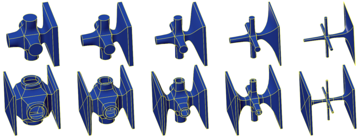
Let be a set of parameters for a family of geometric shapes, topologies and FGM distributions, etc., of a tile . Typically, these parameters will be constrained so critical properties such as the sign of the Jacobian, will not be affected. Figure 3 shows different tiles with parametric control over the wall thicknesses of both solid and hollow , and illustrates parametric control over the diameters of the tubes in a tile.
|
Algorithm 1 can now be modified to accommodate black box optimizations or analysis tools to manipulate the micro-structure. See Algorithm 2.
Input:
: a parametric micro-tile consisting of curves
and/or surfaces and/or trivariates;
: a trivariate parametric deformation macro-function
;
: the initial dimensions of the grid
enumerating tiles in the domain of ;
: an optimizer - a black box that optimizes the
synthesized micro-structure;
Output:
: A micro-structure of tiles
deformed to following the macro-shape of via
functional composition as influenced by
optimizer ;
Algorithm:
In Algorithm 2, the geometry is synthesized using a multi-parameters family of micro-tiles. The optimizer sets the parameters (i.e. wall thickness or pipe diameter) at iteration , to affect only the synthesized geometry at iteration . While Algorithm 2 hints at parameters that control the geometry, the parameters can also control material properties like heat conductivity.
For the first pass of the optimization, Algorithm 2 needs to synthesize an initial micro-structure so the optimizer has something on which to operate. This initial micro-structure is application dependent and in Section 4 we present several such applications.
The presented scheme provides for significant freedom to modify individual micro-tiles while preserving the continuity of the the entire arrangement. If a tile is modified in the domain of the deformation macro-function, and its adjacent micro-tiles are updated accordingly to preserve the continuity, the outcome will preserve continuity as well (assuming the deformation macro-function is sufficiently continuous). Further, the continuity of the geometry must be preserved as well as the continuity of properties such as material. Finally, the modified topology should not affect the continuity. For example, it is infeasible to modify a branching tile from 2 branches to 4 branches without also modifying adjacent tiles to retain continuity properties.
4 Applications and Examples
In this section we present four different design optimization application of micro-structures. In Section 4.1 micro-structures are optimized toward heat exchangers. Section 4.2 considers the question of solid heterogeneous rocket fuel design. In Section 4.3 a wing design based on micro-structures is considered, and finally, in Section 4.4, local thermal control, is optimized in plastic extruders.
4.1 Heat Exchanger
Although often not visible from the exterior of a mechanical system and not the focus of widespread attention, heat exchangers are used universally for heating and cooling functions. Common examples of heat exchangers include radiators, oil coolers, refrigeration/air conditioners/heat pumps, and etc. They occur in a variety of types whose forms are typically driven by applications and traditional manufacturing techniques.
Typically, heat exchangers are selected from a catalog of rectilinear or cylindrical prismatic shapes, thus one is forced to design around the existing standard pre-manufactured shapes. This can lead to awkward, inefficient applications because the design must be adapted to conform to and accommodate the catalog available heat exchanger shapes. The designer is required to adjust the flow so that the conditions at the inlet of the heat exchanger can result in good heat transfer. Additive manufacturing opens the opportunity to design custom heat exchangers specific to the cavity or envelope that naturally occurs in an emerging design.
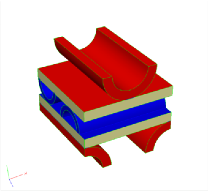
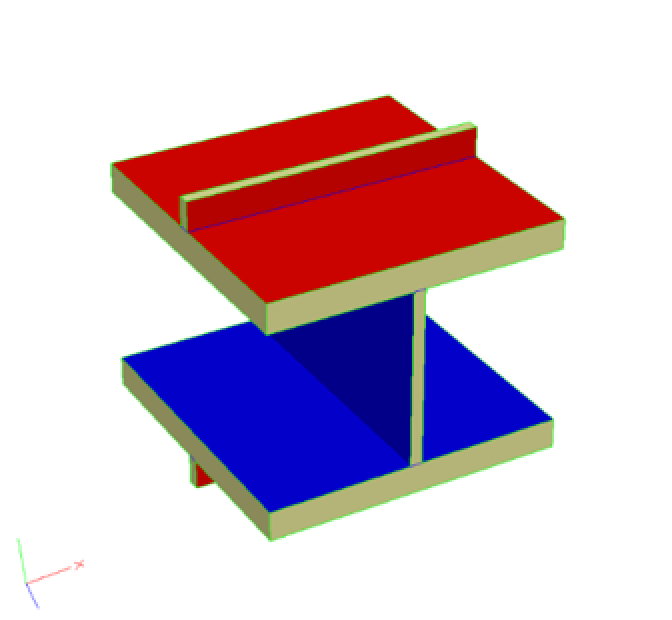
The simplest, inexpensive and most common heat exchangers are manufactured by taking a sandwich of corrugated metal, a metal sheet and then corrugated metal (at 90 degrees to the first corrugated layer), another sheet and then repeating. This suite of plies is then welded together and headers added to create a closed loop for one of the fluids. If one were to generate a single tile of this device it would look like the left-hand image seen in Figure 4. For the rest of the discussion we will be using a simpler repeat pattern that is easily constructed by additive manufacturing and can be seen on the right side of Figure 4.
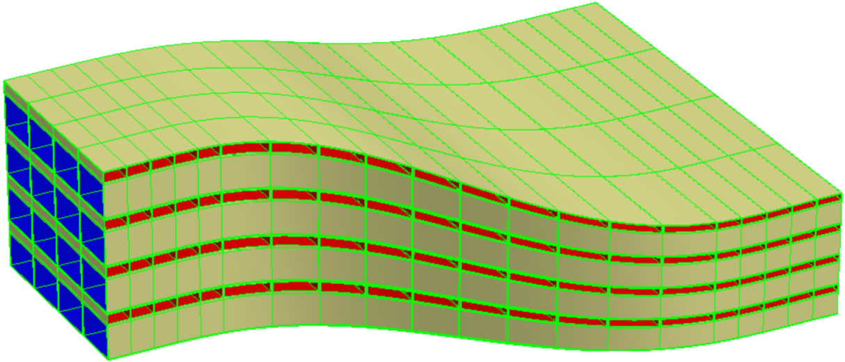
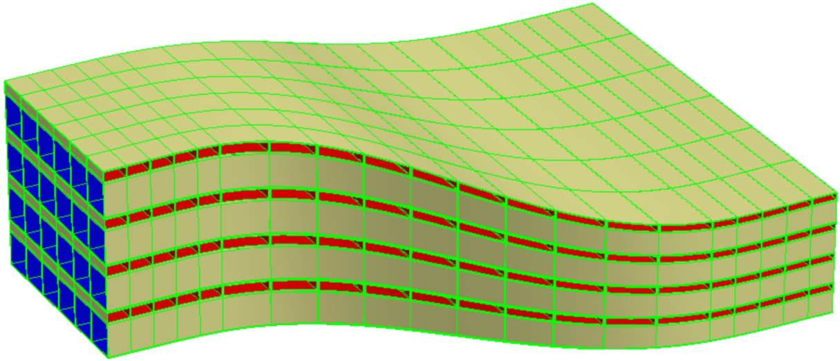
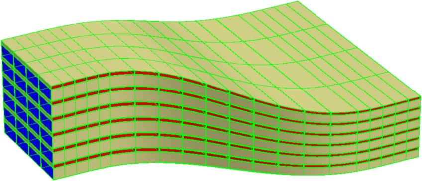
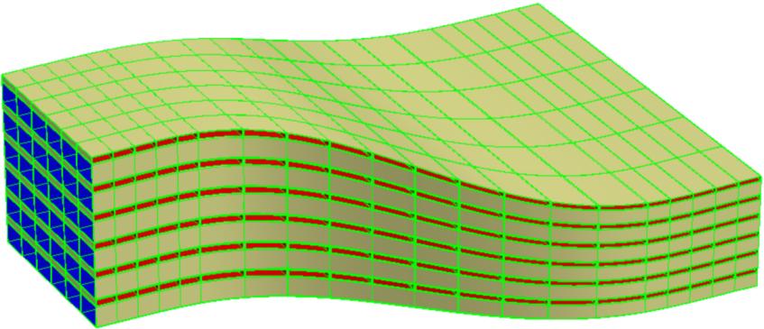
Figure 5 depicts the composition of the tile seen in the right side of Figure 4 into a duct with changing cross-sections. In this case the spacings in the duct are changing, which is driven by the the knot sequence of the geometry that defines the duct ().
An effective heat exchanger maximizes the heat transfer over the entire device. This is not an isolated geometric problem but is a complex heat transfer problem relating the geometry, metal properties, thermal gradients and flow characteristics of the device. A low fidelity, lumped-parameter heat exchanger model has been constructed for this problem that can output trivariate metal thicknesses, hot-to-cold area ratios, and relative tile sizes throughout . The model takes into consideration the physical laws in each hot and cold channel (including temperature and pressure of the appropriate fluid), deals with mass and energy conservation while using a convective heat transfer model. This is accomplished before the geometry of the heat exchanger is composed.
The first step in building the device is to reconstruct the duct so that its knot sequence reflects the relative spacings of the tiles () in physical space (). This is done so that each tile is generated with the appropriate size. Algorithm 3 is then followed, where it should be noted that each tile is individually constructed during the composition. The tile’s parameters are sampled from the scalar trivariate fields, so that after the construction is complete the geometry matches up at the individual tile interfaces. This allows for the building of a coherent structure (by sewing) that can be represented as a geometric solid.
Input:
: a parametric micro-tile consisting of the canonical solid shape;
: a trivariate parametric deformation macro-function;
: a trivariate scalar of hot-to-cold area ratios;
: a trivariate scalar of metal thicknesses;
: the initial dimensions of the grid
enumerating tiles in the domain of ;
Output:
: A micro-structure of tiles
deformed to following the macro-shape of via
functional composition as influenced by
the sizing from the lumped-parameter heat exchanger model;
Algorithm:
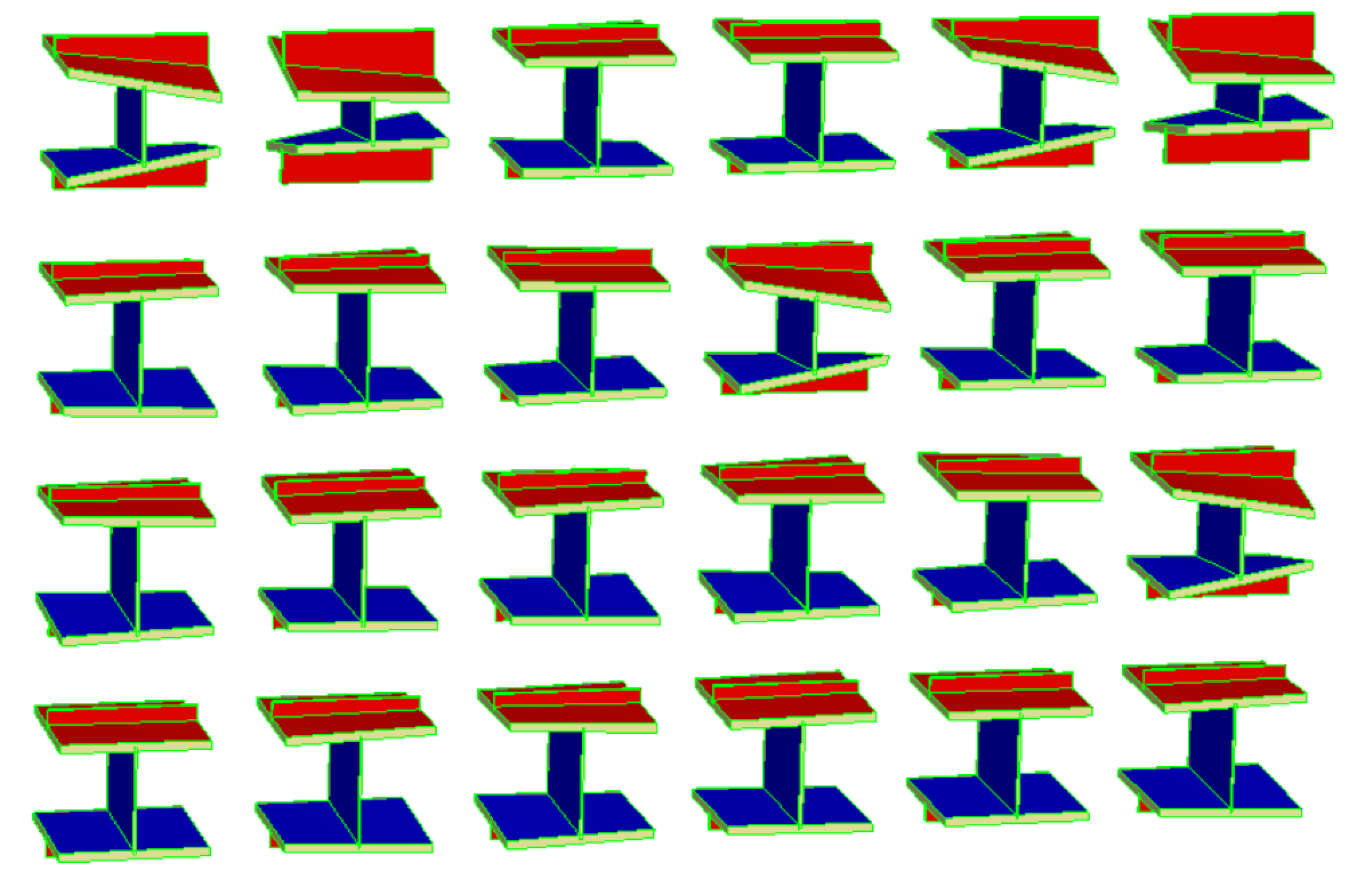
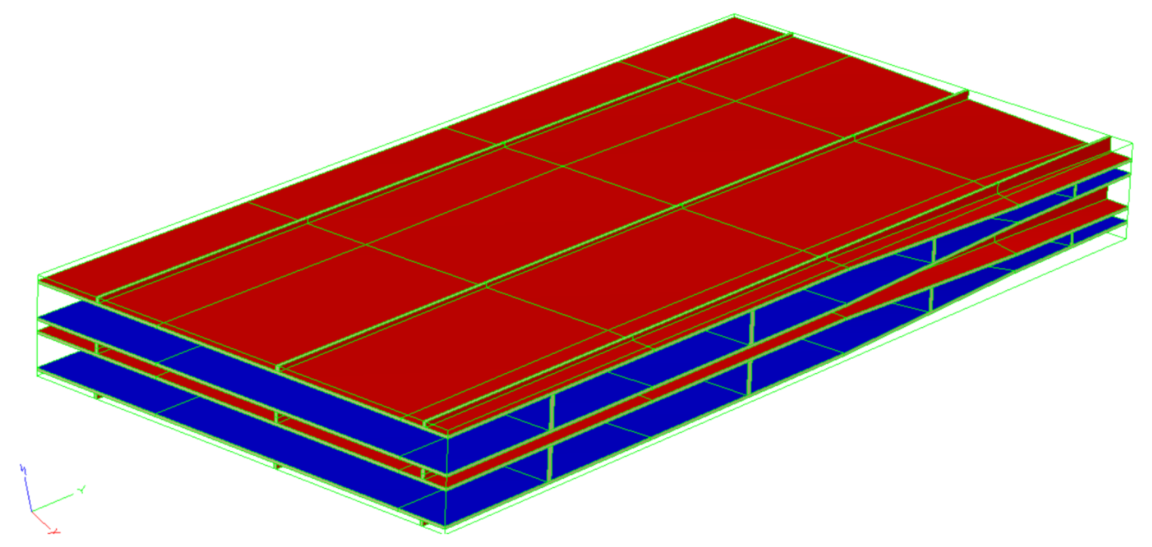
Figure 6 shows the results of Algorithm 3 on a simple rectilinear outer shape with a small number of tiles. The left side of the figure show all of the individual tiles used in the composition (), where the right-hand side of Figure 6 shows the composed result driven by the spacings and thicknesses output from the low fidelity, lumped-parameter heat exchanger model.
4.2 Design of a Solid Fuel Rocket Grain
This application concerns the use of accelerants and retardants mixed with the propellant in a solid rocket engine. Mixing the fuel is considered in order to control and plan the burn rate and thereby the expected thrust. The problem given is to match a prescribed thrust profile and the geometry of the solid fuel rocket casing, which defines the end state of the burn.
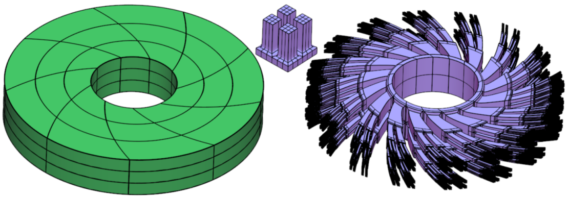
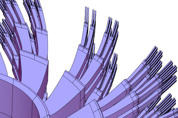
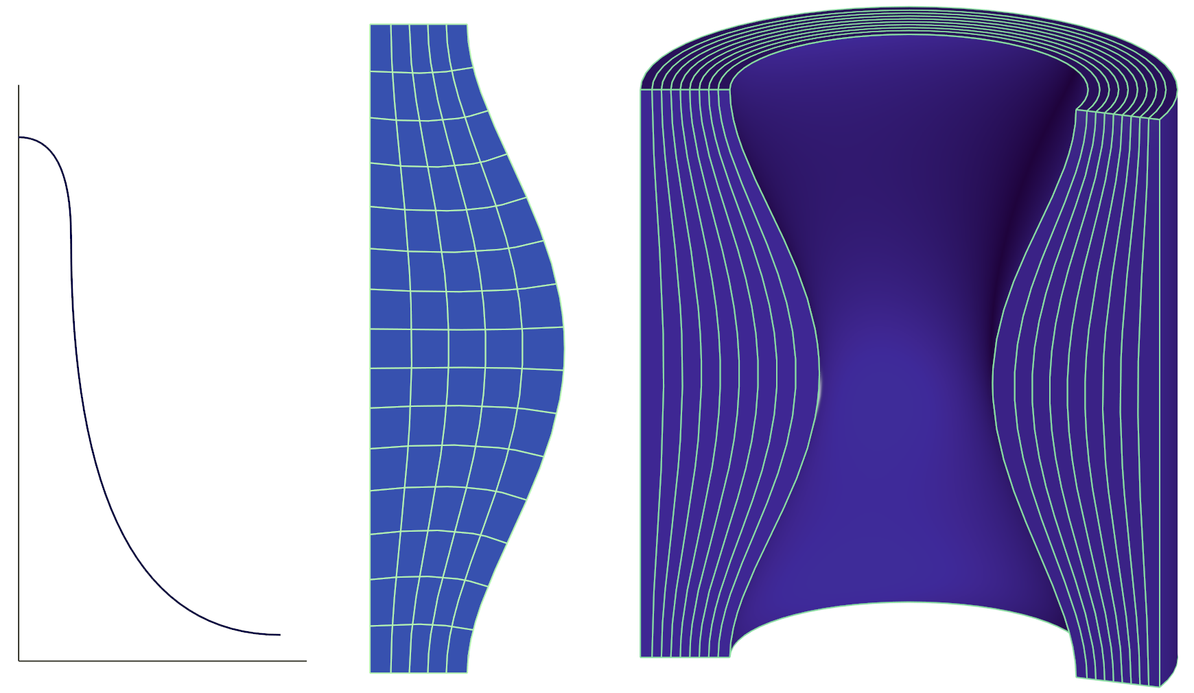
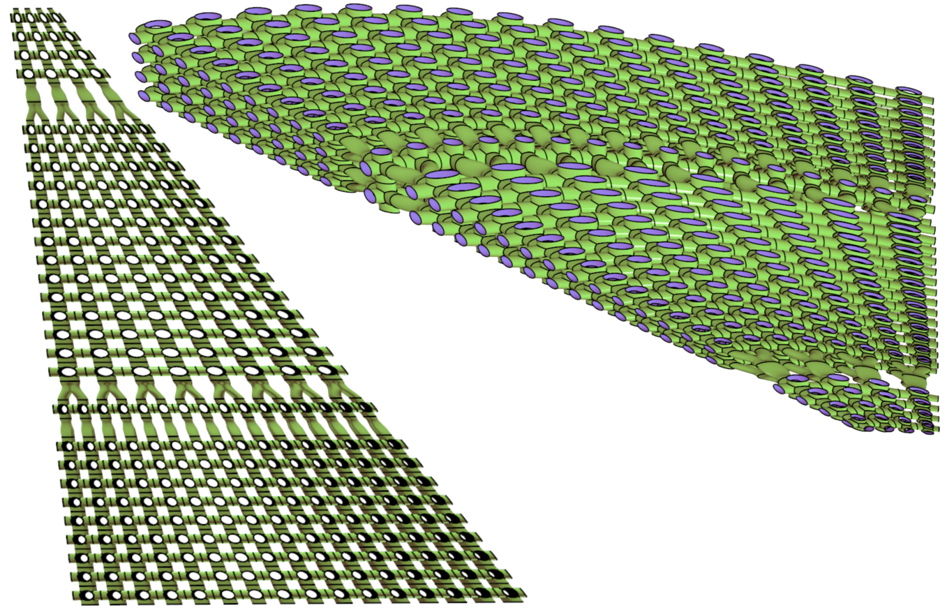
For simplicity and to begin with, we assume that the micro-structure elements are solid and that the geometry of the solid fuel grain is a volume-of-revolution constructed by rotating a 2D planar section about the rocket’s longitudinal axis, not an atypical setting. See Figure 7. In other words, each micro-structure element is a full, possibly heterogeneous, logical cuboid.
|
The micro-structures-based construction scheme of the heterogeneous solid fuel grain follows Algorithm 4.
Input:
: a 2D section of
rocket fuel geometry, being a (orthogonal)
parametrization of the fuel, inside out;
: a thrust profile function, over time;
: micro-structure sampling rate;
Output:
: A micro-structure with heterogeneous composition
(accelerants/retardants)
of a 3D volume-of-revolution shaped fuel grain , with
as its cross section, satisfying
the thrust profile ;
Algorithm:
Algorithm 4 builds the volume-of-revolution (in line 1) by rotating about the rocket’s longitudinal axis, only to partition this trivariate (in line 2) to layers , by subdividing at different values. Note that each is a trivariate as well - see Figure 7 (c). Each layer has a varying thickness. Further, the front surface (burning) area of varies as well, as the burning progresses in the layer. In the limit, however, as goes up and the thicknesses of the layers are vanishing, the front surface area can be assumed fixed. We plan the burning rate (using accelerants/retardants) so each layer will burn completely before the next layer starts to burn. That is, as the burning front progresses, it simultaneously interpolates the next layer. Thus the layers serve literally as synchronization surfaces for the timing of the burn front progression. Then, in line 7-11 of Algorithm 4, we compute for each tile in layer , its burn front area (in ) and depth (in ) and estimate ’s total thrust as its front area times its depth.
|
Accumulating the total thrust that a layer produces as , we globally normalize, in line 15, the relative amount of accelerant or retardant that is required for this layer (time step). This global normalization depends on the ratio between what is the desired thrust at this time step and the basic thrust produced in the layer . Then, in line 18, the global normalization is combined with a local, tile-level, normalization. For tile , the relative depth with respect to the layer’s average depth sets the local normalization. The deeper the tile, the faster it must burn (and hence requires more accelerant) to ensure that the entire layer burns out simultaneously. Then the burn front interpolates the next layer synchronously in time.
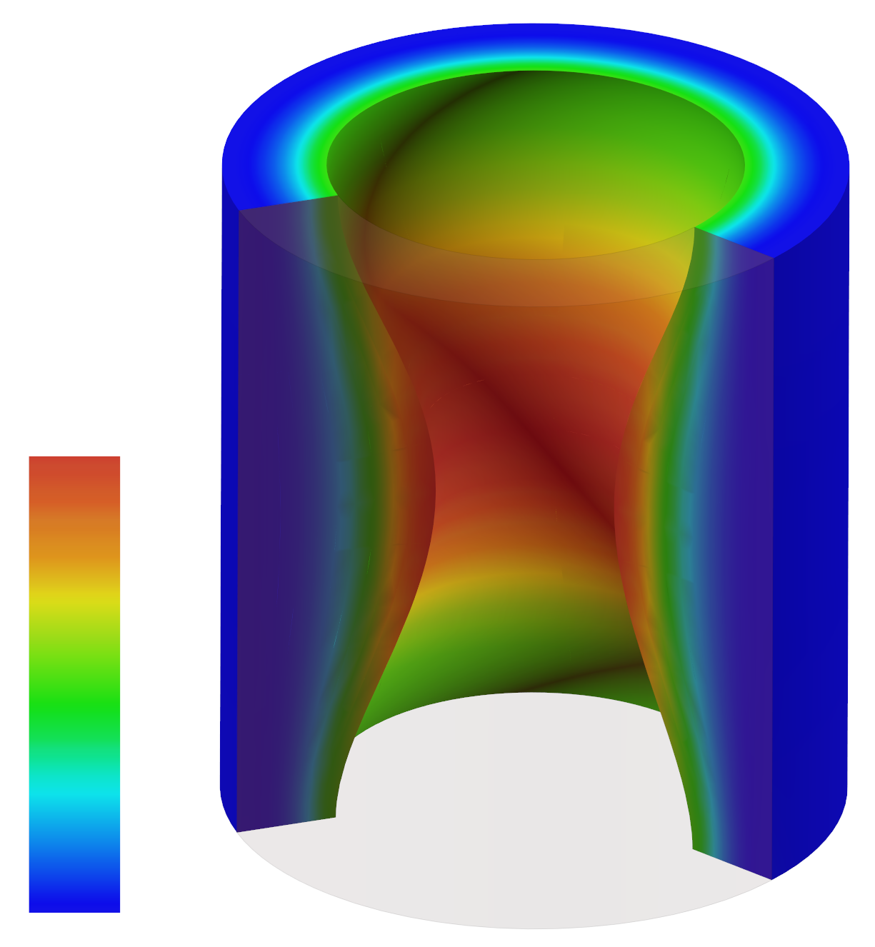
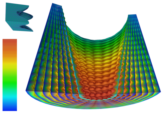
Figure 8 (a) shows one simple result, using the thrust profile and geometry from Figure 7. Figure 8 (b) shows that designing a fuel grain which is not a volume-of-revolution solid fuel is feasible as well. Finally, Figure 8 (c), shows the potential use of porous tiles, in an aim to further increase the burning surface area and hence the thrust.
4.3 Wing Design
Aircraft wings have many functions and their design and packing reflects this complexity. Wings primarily provide lift (due to their outer shape), store fuel, contain mechanisms to provide additional lift during maneuvers such as take-off and landings, hold landing gear and the mechanisms to both extend and retract, and provide the ability to steer the craft through the use of flaps. This means that the internals of wings contain housings for flaps, slats, landing gear, fuel tank(s), and all of the wiring and pneumatic piping (both primary and backup) required for the full functioning of the aircraft. The wing must be able to withstand the forces and stresses encountered during the mission and therefore the internal structures that support the wing must be flexible, robust and light in weight.
Traditionally, manufacturing has given us wing internal structures that are a collection of a small number of spars (usually 2) and a handful of ribs that are usually orthogonal and are all interconnected. The spars and a couple of ribs can form a wing box that may hold fuel. Usually, the ribs have many cutouts to lighten the structure and allow for the running of wiring and piping. Overall, the skin (at least between the spars and the outermost rib) is part of the structure (that is, the skin carries load). At times the expanse of skin (partitioned into bays) allows buckling (not good) and therefore may also require stiffeners to reinforce the structure in appropriate regions.
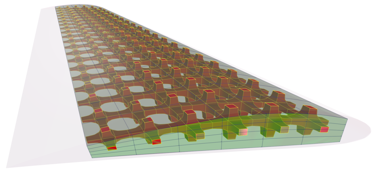
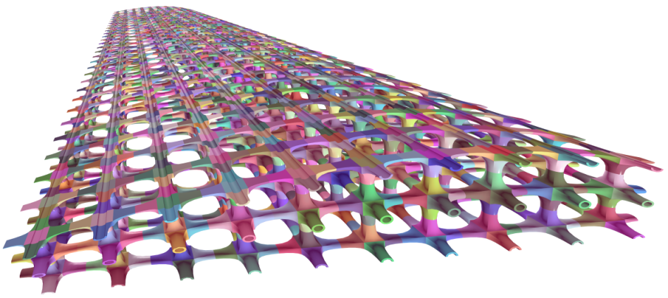
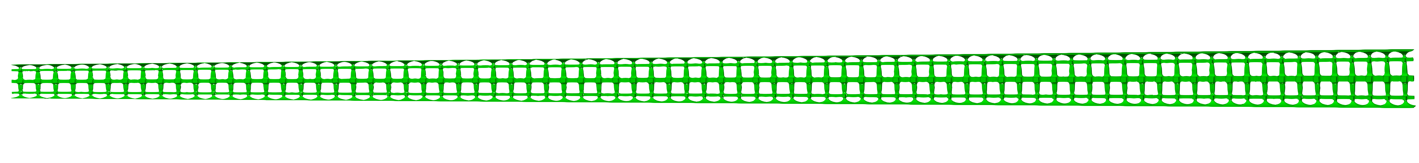
The use of additive manufacturing in building porous, lightweight micro-structures has the potential for fundamentally changing wing structures and therefore wing-structural design. Because the majority of internal space in the wing remains open, routing wiring and piping does not degrade the structural integrity. Fuel can be stored while maintaining the structure by simply cordoning and walling off parts of the micro-structural scaffolding and using the segregated region to hold fuel. The wing’s skin can be an integral part of manufacturing (and not separately applied) by using tiles like those seen in Figure 3. Stiffeners are not required because the unsupported expanse of skin is now much smaller (also the skin itself, as part of the tile, can be locally thickened). The individual tiles can be hollowed to further reduce the weight. See Figure 9.
|
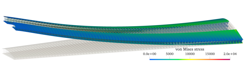
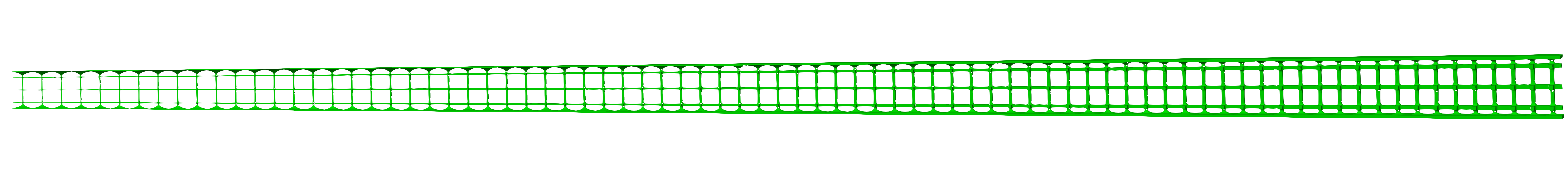
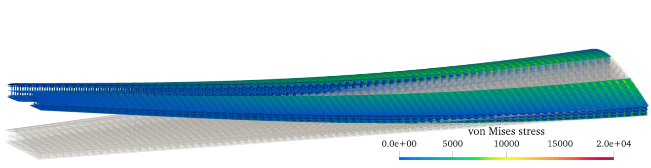
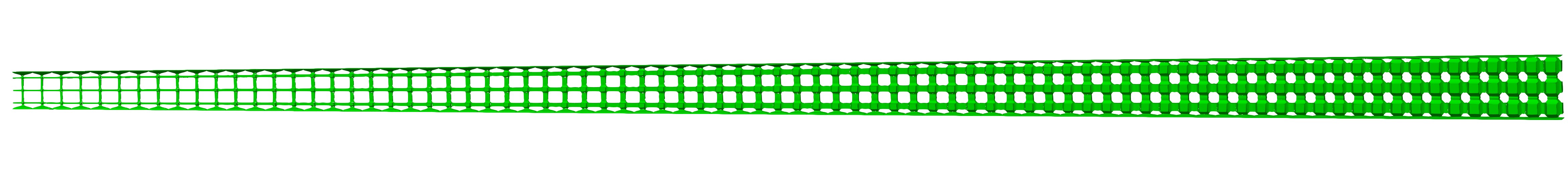
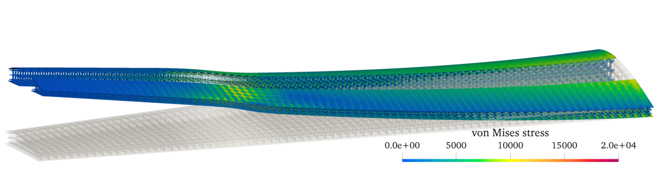
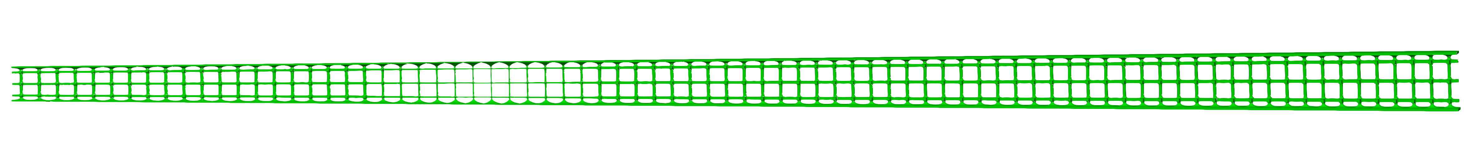
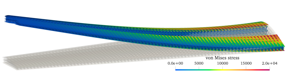
With the aim of exploring the basic structural response of porous wing designs, four different configurations were analyzed in this section (see results in Figure 10).
All the cases considered present the same external wing profile and number of tiles (), with a configuration similar to those shown in Figure 3.
The same type of simulation was carried out for all designs: linear elasticity analysis using the same trivariate parametrizations for the description of the geometry and for the discretization of the solution, following an isogeometric analysis framework (see [8] and references therein).
Each wing configuration presents a total of 51600 tricubic Bézier trivariates, thus, each model has 7 million unknowns: the elastic displacements of each control point in the three Cartesian directions. Contiguous tiles are conforming (the parametrizations of their common faces coincide), therefore, the solution’s continuity is imposed by enforcing the equality of the unknown variables associated to coincident control points111By enforcing the discrete elastic displacement solution to be continuous at the interface between connected trivariates, the number of unknowns is reduced to 7 million from almost 10 ().. In general and much like continuity preservation between surface patches, as long as one preserves the continuity between adjacent tiles in the domain of the deformation function (and the deformation function is sufficiently continuous), the result will preserve continuity. Finally, in the case of non-conforming tiles, the solution’s continuity could be achieved in a weak way by means of mortaring techniques [4]. Using a multiple-core machine (70 threads were used), the computational time was under 40 minutes in all cases. The computations were performed using the isogeometric analysis library igatools [21].
|
|---|
 |
 |
 |
 |
 |
 |
 |
In the structural analyses performed, the wing is fixed at the root, the wider transversal section that connects the wing with the aircraft’s fuselage (the right extremity of the wing in Figure 10). We considered a linear elastic material with a Young modulus to Poisson ratio ratio (typical of steel-based materials). Additionally, in a simplified setting, a uniformly distributed pressure (lift), caused by the aerodynamic loads, was applied on the bottom wing surface. Under these conditions, the wing bends vertically behaving roughly as a cantilever beam: the higher stress concentration appears at the root, whereas the largest wing deflection occurs at the tip. However, as shown in the obtained results, the reduction of the tile’s thicknesses can also induce stress concentrations, as it can be seen at thinner section of the configuration c; or in the case d, in which the presence of thinner tiles in the wing skin, near the root, cause an increase of the stress level, with respect to other designs.
On the other hand, the oscillatory behavior of the stress distributions at the wing skin follows the pattern defined by the tiles distribution. In fact, the amplitude of these oscillations is more accentuated in the case d, that presents a thinner external skin layer.
As a summary, Table 1 gathers the maximum wing deflection, compared to the total volume of wing material (that will determine the wing self-weight, of crucial importance for an aircraft structure), for the four designs studied.
| Case | Relative volume | Relative deflection |
|---|---|---|
| a | ||
| b | ||
| c | ||
| d |
Looking at the table results, the heaviest design (case b) is also the stiffest, as expected. However, as it can be seen for cases a and c, by optimizing the distribution of the tile’s thicknesses, it could be possible to achieve much lighter designs without significantly reducing the wing’s overall stiffness.222In a very simplified setting, considering a solid wing design whose span and chord have a fixed length, the maximum wing deflection can be estimated to be proportional to the cube of its thickness (i.e., to the cube of its volume).
Further design improvements would benefit from the use of multi-objective shape optimization techniques, in which the maximum stress is minimized, while trying to keep a low total volume. The optimizer could operate globally, or over some neighborhood or even on individual tiles, as long as the (geometric as well as material) continuity between adjacent tiles is properly ensured. Indeed, the use of graded materials (see, e.g., [28, 17]) potentially offers a wide range of possibilities in this endeavor.
4.4 Local Heating of Extruders
Plastic profile extrusion is a manufacturing process particularly suited for continuous profiles. These include pipes and floor skirtings, but also more complex geometries, such as window panes. An extrusion line consists of three important parts: (1) an extruder, responsible for melting, mixing, and transporting the raw plastic, (2) the extrusion die, responsible for reshaping the melt to the desired profile, and (3) the calibration, which fixes the profile shape during solidification. With its high influence on the quality of the final product especially in terms of shape accuracy, the extrusion die is certainly the component that has been investigated in most detail. Quality criteria for an extrusion die revolve around shape accuracy of the final product: This is, in particular, influenced by the velocity distribution at the outflow of the extrusion die, as well as the viscoelastic stresses induced within the die. Possible design measures to influence these criteria are the shape of the flow channel within the die, and also the temperature distribution.
In recent years, the research around extrusion dies has been directed towards numerical design methods; i.e., the automated design of the extrusion die, given a certain product shape as input. Ettinger gives an overview of work regarding shape optimization [13]. More recent research can be found in [24, 31, 22]. We note that all of this work is focused on shape optimization of the flow channel. So far, when it comes to simulations, the temperature control within the extrusion die has mostly been considered ideal: In practice, this means that the process is treated as isothermal. This assumption is justified by the heating systems that are currently used: The extrusion die is simply wrapped with a heating band [19].It is clear that such an approach gives no local control over the temperature.
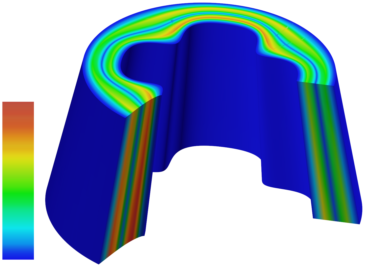
The micro-structuring approach proposed herein could - for the first time - enable local temperature control; this would be achieved without altering the overall mechanism for heating. The extrusion die can still be wrapped with the heating band, but the die would then be micro-structured with material of graded heat conductivity. This would allow for inhomogeneous temperature distributions within the flow channel. As an example, confer with Figure 11. We see an extrusion die intended to produce a floor skirting profile. A common problem arises when there is a higher outflow velocity in the T-junction and a relatively low outflow velocity at the tips of the profile, where wall-adhesion is high due to the high surface area of the wall in this regions. Mitigation of these effects based on flow-channel shape has been investigated in [27]. A similar effect could be achieved with locally reducing temperature in the T-junction, while, at the same time, increasing temperature in the tips. Figure 11 illustrates a possible distribution of micro-structures that would result in the aforementioned temperature distribution.
Furthermore, the use of micro-structuring opens up the realm of developing systems using entirely new temperature control approaches. For example, one could use variable inductive heating, whereby the micro-structures are graded with respect to electrical conductivity.
For this application, the microstructures will be parameterized in terms of their geometry and their material properties. These can then be modified locally with respect to the design objective of homogeneous velocity distribution [12]. In order to keep the number of optimization parameters manageable, expert knowledge will be included into the parameterization. We envision the use of a trust-region optimization algorithm like BOBYQA [23].
|
5 Conclusions and Future Work
We have presented a design paradigm exploiting parametric tiling in micro-structures. Control over both the shape and the materials were presented. Further degrees of freedom to optimize include
-
1.
Control over the size of the micro-structure grid or recursive level or embedding nano-structures within micro-structures, etc. [17].
-
2.
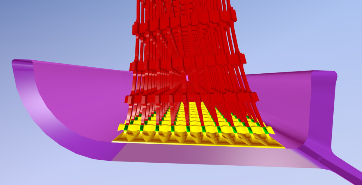
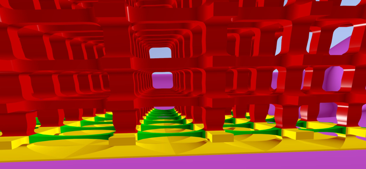
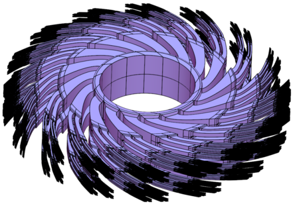
Control over the topology of the tiles, employing tiles with different topologies in different locations. One such potential example is shown in Figure 12 where bifurcations are employed. This example employs tiles with (trimmed) surfaces and contiguous surfaces in the tiles that are not conforming. For simpler analysis and optimization, it is better to design with conforming (preferably untrimmed) trivariate based tiles.
- 3.
|
|
The example in Figure 12 demonstrates the potential in an effort to keep all tiles of uniform size. Such a constraint is typically application driven (i.e. minimal thickness walls in additive manufacturing) and is not a limit of the presented process. The micro-tiles can be deformed arbitrarily. Further, as many tiles as desired can fit into one deformation macro-function. It is limited only by computer memory needs and computational costs.
Up to continuity requirments, the different tiles in the domain of the deformation macro-function are independent and can be arbitrarily different (and even random). Each tile can present a different topology, geometry or material properties. How this generality will be fully exploited in design is yet to be seen.
There has been a great deal of recent interest in the use of Topological Optimization to generate interesting (and sometimes unintuitive) structural designs. This focus is partially due to the commonalities with additive manufacturing that both use the same volumetric underpinning (voxels). This means that a structural design can be simply printed without translation. But like any engineering tool there are limitations, which in this case include: deep optimal designs (which can be fragile), difficulties when surface smoothness is critical, compatibility with contemporary CAD systems, and dealing with designs where (structural) analysis is only one of many disciplines in play.
It is the last point above (designs for multi-physics devices) when micro-structures provide a general viable alternative to voxels and therefore the possibility to design in multidisciplinary settings. Examples of this can be seen throughout Section 4 where the outer/macro shape need not be rectilinear and the micro-shapes have few limitations. The difficulty in this design setting is that the number of parameters that drive the design through optimization can be quite large (and some continuous). This can be effectively handled in a gradient-based optimization manner where the parametric derivatives for the entire problem are available. Generating these derivatives can efficiently be accomplished through the use of tightly coupled physics solvers that include their Adjoint so that the full Jacobian of the coupled problem can be made available. Then the chain-rule can be applied to couple the Jacobian to the parametric derivatives produced from differentiating the geometry construction.
Acknowledgments
This research was supported in part by the ISRAEL SCIENCE FOUNDATION (grant No. 597/18) and in part with funding from the Defense Advanced Research Projects Agency (DARPA), under contract HR0011-17-2-0028. The views, opinions and/or findings expressed are those of the author and should not be interpreted as representing the official views or policies of the Department of Defense or the U.S. Government. Pablo Antolin and Annalisa Buffa gratefully acknowledge the support of the European Research Council, through the ERC AdG n. 694515 - CHANGE.
References
References
- [1] Amadio, G., and Jackson, T. L. A new packing code for creating microstructures of propellants and explosives. In 51st AIAA/SAE/ASEE Joint Propulsion Conference (July 2015), pp. 1–13.
- [2] Armillotta, A., and Pelzer, R. Modeling of porous structures for rapid prototyping of tissue engineering scaffolds. The International Journal of Advanced Manufacturing Technology 39, 5 (Nov 2008), 501–511.
- [3] Bornoff, R., and Parry, J. An additive design heatsink geometry topology identification and optimisation algorithm. In 2015 31st Thermal Measurement, Modeling Management Symposium (SEMI-THERM) (March 2015), pp. 303–308.
- [4] Brivadis, E., Buffa, A., Wohlmuth, B., and Wunderlich, L. Isogeometric mortar methods. Comput. Methods Appl. Mech. Engrg. 284 (2015), 292–319.
- [5] Burczyński, T., and Kuś, W. Microstructure optimization and identification in multi-scale modelling. Springer Netherlands, Dordrecht, 2009, pp. 169–181.
- [6] Chu, C., Graf, G., and Rosen, D. W. Design for additive manufacturing of cellular structures. Computer-Aided Design and Applications 5, 5 (2008), 686–696.
- [7] Conde-Rodríguez, F., Torres, J.-C., García-Fernández, Á.-L., and Feito-Higueruela, F.-R. A comprehensive framework for modeling heterogeneous objects. The Visual Computer 33, 1 (Jan 2017), 17–31.
- [8] Cottrell, J. A., Hughes, T. J. R., and Bazilevs, Y. Isogeometric Analysis: Toward Integration of CAD and FEA, 1st ed. Wiley Publishing, 2009.
- [9] DeRose, T. D., Goldman, R. N., Hagen, H., and Mann, S. Functional composition algorithms via blossoming. ACM Trans. Graph. 12, 2 (Apr. 1993), 113–135.
- [10] Elber, G. Free form surface analysis using a hybrid of symbolic and numerical computation. PhD Thesis, University of Utah, 1992.
- [11] Elber, G. Precise construction of micro-structures and porous geometry via functional composition. In Proceedings of the 9th International Conference on Mathematical Methods for Curves and Surfaces (2016), pp. 108–125.
- [12] Elgeti, S., Probst, M., Windeck, C., Behr, M., Michaeli, W., and Hopmann, C. Numerical shape optimization as an approach to extrusion die design. Finite Elements in Analysis and Design 61 (2012), 35–43.
- [13] Ettinger, H. J., Pittman, J. F. T., and Sienz, J. Optimization-driven design of dies for profile extrusion: Parameterization, strategy, and performance. Polymer Engineering & Science 53, 1 (2013), 189–203.
- [14] Gao, W., Zhang, Y., Ramanujan, D., Ramani, K., Chen, Y., Williams, C. B., Wang, C. C., Shin, Y. C., Zhang, S., and Zavattieri, P. D. The status, challenges, and future of additive manufacturing in engineering. Computer-Aided Design 69, Supplement C (2015), 65 – 89.
- [15] Kendall, W. S., and van Lieshout, M. Stochastic geometry: Likelihood and computation. Chapman and Hall/CRC, London, 1998.
- [16] Leblanc, L., Houle, J., and Poulin, P. Modeling with blocks. The Visual Computer 27, 6 (Apr 2011), 555.
- [17] Massarwi, F., Machchhar, J., Antolin, P., and Elber, G. Hierarchical, random and bifurcation tiling with heterogeneity in micro-structures construction via functional composition. Computer Aided Design 102 (2018), 148–159.
- [18] Medeiros e Sá, A., Mello, V. M., Rodriguez Echavarria, K., and Covill, D. Adaptive voids. The Visual Computer 31, 6 (Jun 2015), 799–808.
- [19] Michaeli, W. Extrusionswerkzeuge für Kunststoffe und Kautschuk. Carl Hanser Verlag, 1991.
- [20] Pasko, A., Fryazinov, O., Vilbrandt, T., Fayolle, P.-A., and Adzhiev, V. Procedural function-based modelling of volumetric microstructures. Graphical Models 73, 5 (2011), 165 – 181.
- [21] Pauletti, M. S., Martinelli, M., Cavallini, N., and Antolin, P. Igatools: An isogeometric analysis library. SIAM Journal of Scientific Computing 37, 4 (2015), 465 – 496.
- [22] Pauli, L., Behr, M., and Elgeti, S. Towards shape optimization of profile extrusion dies with respect to homogeneous die swell. Journal of Non-Newtonian Fluid Mechanics 200, 79-87 (2013).
- [23] Powell, M. J. The bobyqa algorithm for bound constrained optimization without derivatives. Cambridge NA Report NA2009/06, University of Cambridge, Cambridge (2009), 26–46.
- [24] Rajkumar, A., Ferrás, L., Fernandes, C., Carneiro, O., Becker, M., and Nóbrega, J. Design guidelines to balance the flow distribution in complex profile extrusion dies. International Polymer Processing 32, 1 (2017), 58–71.
- [25] Rumpf, R. C., Pazos, J. J., Digaum, J. L., and Kuebler, S. M. Spatially variant periodic structures in electromagnetics. Philos Trans A Math Phys Eng Sci. 373 (2015).
- [26] Schroeder, C., Regli, W. C., Shokoufandeh, A., and Sun, W. Computer-aided design of porous artifacts. Computer-Aided Design 37, 3 (2005), 339 – 353. Heterogeneous Object Models and their Applications.
- [27] Siegbert, R., Elgeti, S., Behr, M., Kurth, K., Windeck, C., and Hopmann, C. Design criteria in numerical design of profile extrusion dies. Key Engineering Materials 554 (2013), 794–800.
- [28] Stanković, T., Mueller, J., Egan, P., and Shea, K. A Generalized Optimality Criteria Method for Optimization of Additively Manufactured Multimaterial Lattice Structures. J. Mech. Des 137, 11 (Nov. 2015), 111405.
- [29] Wang, H., Chen, Y., and Rosen, D. A hybrid geometric modeling method for large scale conformal cellular structures. In Volume 3: 25th Computers and Information in Engineering Conference, Parts A and B (January 2005).
- [30] Xiao, F., and Yin, X. Geometry models of porous media based on voronoi tessellations and their porosity-permeability relations. Computers and Mathematics with Applications 72, 2 (2016), 328 – 348. The Proceedings of ICMMES 2014.
- [31] Zhang, C., Yang, S., Zhang, Q., Zhao, G., Lu, P., and Sun, W. Automatic optimization design of a feeder extrusion die with response surface methodology and mesh deformation technique. The International Journal of Advanced Manufacturing Technology 91, 9-12 (2017), 3181–3193.