Analytical Modeling of UAV-to-Vehicle Propagation Channels in Built-Up Areas
Abstract
This letter presents an analytical path loss model for air-ground (AG) propagation between unmanned aerial vehicles (UAVs) and ground-based vehicles. We consider built-up areas, such as the ones defined by ITU-R. The three-dimensional (3D) path loss model is based on propagation conditions and essential parameters are derived by using geometric methods. Owing to the generality, the analytical model is capable of arbitrary deployments of buildings, such as suburban, urban and dense urban. The analytical model is evaluated numerically, and validations conducted by ray-tracing simulations show the high accuracy of the proposed model. The closed-form analytical formulas provide a useful tool for quick and accurate prediction of UAV-to-vehicle propagation channels.
Index Terms:
Air-ground (AG), analytical modeling, built-up areas, multipath, propagation, ray tracing, UAV.I Introduction
The advent of the internet of everything (IoE) in the fifth generation and beyond (5GB) wireless systems will give rise to a new category of use cases termed air-ground (AG) integrated communication, where aerial and terrestrial terminals are interconnected. As an example, unmanned aerial vehicles (UAVs) serving as users can connect to a cellular base station (BS) [1], but can also act as aerial BSs to provide data services for ground terminals (such as smartphones or vehicles). The UAV-to-vehicle communication is anticipated to play a critical role in the traffic control system and emergency communication. UAVs can assist vehicular networks by acting as intermediate relays or BSs. UAVs can also be deployed in an area where a disaster occurs, and therefore acts as bundle carriers and relays. However, the requirements in control, communication and navigation pose challenging issues to system designers of integrated networks. In particular, modeling the UAV-to-vehicle propagation channel remains an open issue, especially in built-up areas. Such environments have many potential scatterers composed of buildings, which will cause the channel to experience severe multipath effects. Additionally, because the altitude of the UAV may change, it is important to consider three-dimensional channel models that take the altitude of the transceiver into account.
The literature on AG channel characterization and modeling is sparse, and the existing work focuses on measurement-based and geometry-based approaches. Measurement campaigns were conducted for different scenarios such as urban, over-water and mountain area in [2], where tapped delay line (TDL) models were presented. However, since the measurement were carried out at a single altitude, they are insufficient for setting up an altitude-dependent model. In [3, 4], authors discuss a more generic geometry-based stochastic model (GBSM), with the assumption that scatterers are distributed stochastically on a cylinder and an ellipsoid, respectively. In the above methods, measurement based on the specific scenarios lead to a lack of generality. Moreover, GBSM have trouble reflecting realistic performance metrics that can be observed in real scenarios. As a tradeoff, three-dimensional analytical model become more promising for quick and accurate prediction of UAV-to-vehicle channels.
Despite their obvious importance, UAV-to-vehicle channels have received little attention. Authors in [5] focused on transmission rates and packet losses of UAV-to-car communications while ignoring the complex channel characteristics. In this paper, we present the importance of AG channel modeling and propose an analytical channel model for UAV-to-vehicle communication. The main contributions of this work can be summarized as follows: (1) a novel path loss model is proposed with consideration of the scenario characteristics defined by ITU-R, (2) the critical parameters of the multipath channel are derived, and (3) validations by ray-tracing simulations are conducted in the reconstructed Manhattan scenario based on a real environment [6].
The remainder of this letter is organized as follows. In Section II, we introduce the general scenarios defined by ITU-R and present the derivation of the analytical model. Section III presents numerical results and analysis. Besides, validations based on ray-tracing simulations of the proposed model are conducted. Conclusions are drawn in Section IV.
II Propagation Modeling in Built-Up Areas
II-A Scenario Description
In order to set up a generic path loss model in BU areas, the statistical ITU-R Rec. P.1410 model for building deployments is adopted [7]. An advantage of this model is that the area can be modeled without precise information concerning building shapes and distributions. The statistical model requires only three empirical parameters describing the built-up area: the ratio of the land area covered by buildings to the total land area (), the average number of buildings per unit area (), and a parameter for determining the distribution of building height (). Typical values for these three empirical parameters are listed in Table I. The probability density function (PDF) for the building height is based on a Rayleigh distribution and is given by
| (1) |
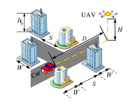
In this study, the virtual-city environment is chosen similar to a Manhattan grid [8]. Fig. 1(a) shows such an environment, composed of an array of structures of width and inter-building spacing . The parameters and are measured in meters and can be linked to the ITU-R statistical parameters, since by definition = / (where is the map side measured in kilometers), and is the number of buildings. The parameters can be linked to the ITU-R parameters by . Thus, we can calculate and as follows: and . Fig. 1(a) shows the environment representation with essential parameters for UAV-to-vehicle communication in built-up areas. Note that parameters in Table I are the typical values of standard cities. In channel modeling, we can use special values which are obtained according to the actual sizes of environments.
| Environment | |||
|---|---|---|---|
| Suburban | 0.1 | 750 | 8 |
| Urban | 0.3 | 500 | 15 |
| Dense Urban | 0.5 | 300 | 20 |
| High-rise Urban | 0.5 | 300 | 50 |
II-B UAV-to-Vehicle Path Loss Model in Built-Up Scenarios
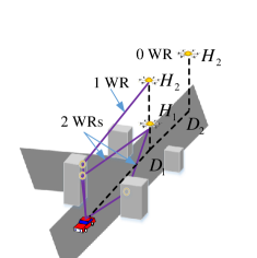
For the BU case, we found that the channel is well modeled by a two-ray (TR) model consisting of the direct path and the ground reflection, plus intermittent multipath components (MPCs) which are determined according to the altitude of UAV and the horizontal distance. Note that due to the long path travelling, the power of diffractions and high-order reflections is insignificant, which can be neglected in the modeling of path loss. As shown in Fig. 1(b), at a distance of and a lower altitude , the number of wall reflection (WR) may be two. When the height increases to (at the same distance ), the reflection may become only one since the height of potential reflected point increases as the height of UAV increases. Another geometrical consideration for the WR the space between buildings, for example, at a distance of . At this location, there is no WR regardless of the altitude of UAV. Thus, according to the different conditions of propagation and the TR model in [9], the path loss model for UAV-to-vehicle propagation channels can be expressed as
| (2) | ||||
where is the wavelength and is the link distance. and are reflection coefficient for the building and the ground, respectively. and are the phase differences between the wall or ground reflection and the line-of-sight (LOS), respectively, which can be calculated by
| (3) |
where where is the antenna height mounted on the top of vehicle. and are the path length of building reflection and ground reflection, respectively. According to the relationship of geometry, can be calculated by
| (4) |
In this paper, we assume the ground vehicle is at the center of the road while the UAV also flies along the center of the road, which means that the distances to the buildings on either side of the vehicle (and their ground projections) are . Thus, the path length of two-side wall reflections is the same and can be calculated by
| (5) |
where the calculation is derived based on the geometry.

II-C Periodic Characteristic of the Wall Reflection
As shown in Fig. 2(a), when the UAV flies along the road the reflection point of the WR changes. If the UAV and the ground vehicle are static, the WR can be determined according to the geometry of the environment. If the UAV (or the vehicle) moves, the WR behavior will become periodic as the UAV (or the vehicle) travels from building to building. As can be seen in Fig. 2(a), there is a WR when the potential reflection point is on the wall. When the potential reflection point moves to the space in between buildings, there is no WR. Note that we assume here that the altitude of UAV is lower than the critical altitude which is derived in the next subsection. In addition, it should be noted that the WRs happen from the buildings on both sides of the road.
II-D Determining the Critical Altitude of UAV
As shown in Fig. 1(b), increasing the altitude of UAV will lead the WR to disappear. Thus, it is important to calculate the critical altitude of UAV. In other words, we want to determine whether a WR occurs based on the heights of the buildings, vehicle and UAV. Note that the following deduction assumes the potential reflection points are on the wall. We introduce the heights of the buildings on both sides of the road as and , respectively. For the UAV-to-vehicle case, the height of the vehicle is fixed and lower than the building height so that the vital issue to determine the number of WR is to find the critical altitude of the UAV. We show that the critical altitude of the UAV is given by
| (6) |
where is the critical altitude of UAV, is the antenna height of vehicle and is the height of building producing the potential reflections. Thus, when the altitude of UAV and , there will be two WRs. Similarly, when or , there will only be one WR. When and , there is no WR.
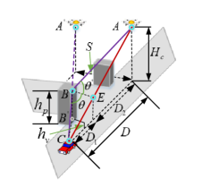
Proof: As shown in Fig. 2(b), the mirror symmetry point of the UAV about the wall is . Eq. (5) can easily be deduced by simple geometry. In order to obtain the critical altitude of UAV, we assume the reflected point is on the top edge of the building with a height of . According to Snell’s law, =. We make a vertical line from point and intersect it with the LOS at point . Since =, and , we can state that . Therefore it can be established that and . Thus, can be calculated by
| (7) |
where is actually equal to . By substituting Eq. (7) into Eq. (5), we can obtain .
III Numerical Results and Validation
III-A Numerical Results
This section provides simulation results. We set the carrier frequency at 4 GHz which is in the typical range for UAV and vehicle communications [2, 5]. For simplification, we assume = = 1. The scenario is urban, and the parameters are listed in Table I so that we can calculate m and m. The altitude of UAV is set to 50 m, and the height of the vehicle is 1.5 m. Fig. 3 shows the periodicity of WR because of the changing horizontal position of the UAV. When the number of multipath is 2, the WR are non-existent. Note that the heights of the buildings are randomly generated and the critical altitudes are calculated with Eq. (6). Thus, the WR can be 0, 1 and 2 because of the random heights of the buildings.
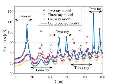
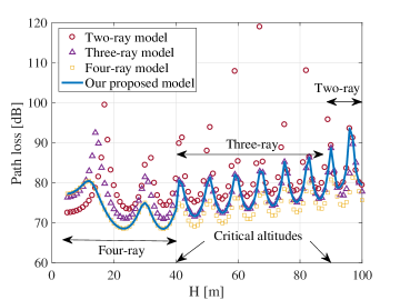
Fig. 4 shows that as the altitude of UAV rises, the number of multipath changes linearly, which is different from the periodic characteristics when the horizontal position of the UAV changes. In the simulation, the two critical altitudes (corresponding to the buildings on the two sides of the road) are calculated so that when the altitude of UAV is lower than the smaller critical altitude, the number of WR is 2; when the UAV altitude is between the two critical altitudes, the number of WR is 1. Once the altitude higher than largest critical altitude, there is no WR.
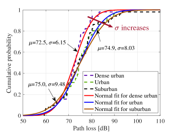
For different scenarios, we compare the path loss in Fig. 5. We obtain the path loss result when 50 m and varies from 0 to 100 m. The sizes of the scenarios are obtained according to the parameters in Table I. The cumulative probability density functions (CDFs) are plotted and optimally fitted by Normal distribution. We observe that the mean values () of them are similar and around 72.5-75 dB. However, the standard deviation presents a noticeable difference. The trend is the following: as the density of building decreases, that is, from dense urban to urban to suburban, changes from 6.15 dB to 8.03 dB to 9.48 dB. It is hard to understand since we take it for granted that the density of building decreases, the level of path loss fluctuation (the physical meaning of ) will become smaller owing to fewer rays. In fact, due to the larger space between buildings in the lower density scenario, the periodic characteristic of multipath is more evident for the UAV-to-vehicle channel so that fluctuations become larger. Another reason is that more WRs in the higher density scenes lead to smaller fluctuations of the path loss.
III-B Validation for Proposed Model by Ray Tracing
We validate our proposed model by ray-tracing simulation, which has been verified as a method for channel modeling by massive measurements in Europe, South Korea, and America. The digital map shown in Fig. 6(a) is based on a real environment in Manhattan, New York and obtained from the OpenStreet website. The CDF of the building height is plotted in Fig. 6(b). The result () of Rayleigh fit is 87.3. Besides, the size of the scenario is marked. The simulation is conducted at 4 GHz, the altitude of UAV and vehicle is set to 200 m and 1.5 m, respectively, and the horizontal location of the UAV goes from 0 to 225 m.

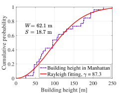
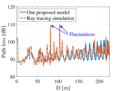
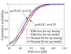
Fig. 7 shows a comparison between the proposed model and the ray-tracing simulations. The results indicate that our proposed model shows good agreement with the ray-tracing result. The mean values and standard deviations of the path loss for our model and ray tracing is 91.87 dB, 4.21 dB, and 92.87 dB, 4.25 dB respectively. Similar results show the accuracy of our proposed model. However, due to the randomness of building height in our model and the relative irregularity of Manhattan scenario, the large fluctuations of the path loss at two locations are not well taken into account with our model. In general, however, our model can provide a reasonably accurate prediction for UAV-to-vehicle communication.
IV Conclusion
In the paper, we proposed an analytical path loss model for predicting the propagation channel of UAV-to-vehicle scenarios. The corresponding parameters are derived based on a geometrical method. We found that the number of multipath changes by the way of periodicity and linearity in the horizontal and vertical dimension, respectively. Besides, the standard deviation of path loss decreases as the density of building increases, which is different from traditional channels. Finally, the accuracy of the proposed path loss model is validated by ray-tracing simulations conducted in a realistic environment. The study of this paper can be used to guide the design and deployment for UAV-to-vehicle communications.
References
- [1] Y. Zeng, J. Lyu and R. Zhang, “Cellular-connected UAV: potential, challenges, and promising technologies,” IEEE Wireless Commun., vol. 26, no. 1, pp. 120-127, Feb. 2019.
- [2] D. W. Matolak and R. Sun, “Unmanned aircraft systems: air-ground channel characterization for future applications,” IEEE Veh. Technol. Mag., vol. 10, no. 2, pp. 79-85, Jun. 2015.
- [3] X. Cheng and Y. Li, “A 3D geometry-based stochastic model for UAV-MIMO wideband non-stationary channels,” IEEE Internet Things, PP (99), Oct. 2018.
- [4] S. M. Gulfam, J. Syed, M. N. Patwary and M. Abdel-Maguid, “On the spatial characterization of 3-D air-to-ground radio communication channels,” in Proc. IEEE Intl. Conf. on Commun. (ICC), London, UK, Jun. 2015, pp. 2924-2930.
- [5] S. A. Hadiwardoyo, C. T. Calafate, J. Cano, Y. Ji, E. Hernández-Orallo and P. Manzoni, “3D simulation modeling of UAV-to-car communications,” IEEE Access, vol. 7, pp. 8808-8823, Dec. 2018.
- [6] D. He, B. Ai, K. Guan, L. Wang, Z. Zhong and T. Kürner, “The design and applications of high-performance ray-tracing simulation platform for 5g and beyond wireless communications: a tutorial,” IEEE Commun. Surveys Tuts., vol. 21, no. 1, pp. 10-27, Aug. 2018.
- [7] P Series, “Propagation data and prediction methods for the design of terrestrial troadband millimetric radio access systems,” Int. Telecommun. Union, Rep. ITU-R Rec. P.1410-2, 2003.
- [8] A. Al-Hourani, S. Kandeepan, and A. Jamalipour, “Modeling air-to-ground path loss for low altitude platforms in urban environments,” in Proc. IEEE GLOBECOM Symp. Sel. Areas Commun., Satellite Space Commun., Austin, TX, USA, Dec. 2014, pp. 1-7.
- [9] R. He, Z. Zhong, B. Ai, J. Ding and K. Guan, “Analysis of the relation between fresnel zone and path loss exponent based on two-ray model,” IEEE Antennas Wireless Propag. Lett. vol. 11, pp. 208-211, Feb. 2012.