FEM-based Scalp-to-Cortex data mapping via the solution of the Cauchy problem
Abstract
We propose an approach and the numerical algorithm for pre-processing of the electroencephalography (EEG) data, enabling to generate an accurate mapping of the potential from the measurement area - scalp - to the brain surface. The algorithm based on the solution of ill-posed Cauchy problem for the Laplace’s equation using tetrahedral finite elements linear approximation. Application of the proposed algorithm sufficiently increases the spatial resolution of the EEG technique, making it comparable with much more complicated intracranial EEG techniques.
keywords:
Cauchy problem, ill-posed problem, electroencephalography, mathematical modelling, medical physics, electrostatics1 Introduction
The majority of existing methods for EEG data processing and source analysis falls into the following categories: parametric inversions (the dipole fitting), current-reconstruction methods ([1, 2, 3, 4, 5, 6]) and, somewhat less frequently, beamforming methods ([7, 8, 9, 10]. The approaches are very different (sometimes, fundamentally). All of them, however, use the EEG measurements as enter data and, thus, highly depend on its quality.
The measured electrical potential is strongly distorted by outer (with respect to the brain) head tissues. The current research is aimed to improve the EEG data via partial excluding the influence of the outer tissues on the EEG signal.
Since the outer compartments (tissues) do not contain any sources producing the objective signal, the electric potential related to the brain sources satisfies the Laplace’s equation there. Measuring the potential on the part of the head surface makes it possible to state the Cauchy problem for the Laplace’s equation in order to map the data from the scalp to the brain surface. Such mapping is an auxiliary problem, allowing to sufficiently increase the accuracy of source localization due to better quality and spatial resolution of enter data.
The Cauchy problem for the data mapping in the context of EEG was considered in [11], where authors propose to use the boundary elements method (BEM) in order to construct the cost functional for further minimization of it. The method, however, probably may have some drawbacks common for the BEM techniques. It is known that the conventional BEM (i.e., double layer formulation) accuracy degrade when the distance between the source and one of the surfaces becomes smaller [12]. Beyond this, when two surfaces approach each other, the resulting system of linear equations tends to be singular. Further, conventional BEM cannot incorporate conductivity anisotropies. Finally, numerical comparison presented in [13] indicated much higher modelling errors in the BEM versus finite element method (FEM).
In the current paper, we use the technique based on the mixed quasi-reversibility (MQR) method for linear finite elements and proposed by L.Bourgeois in [14]. The method allows to reduce the Cauchy problem to the system of linear equations per compartment, built using two regularization parameters, the choice of which is also considered in [14, 15]. As we show later, the application of our algorithm enables us to ’focus’ a measured signal, sufficiently improving its spatial resolution even in complicated cases of in-brain source currents.
Regarding practical use of the proposed method, it can be applied either directly to detect active parts of the cortex or as an intermediate procedure to propagate data from scalp to cortex before employing other processing techniques. Though in this study we focused only on mathematical and numerical aspects, we believe that the proposed method may serve as a basis for fast and accurate algorithms for analysis of real EEG data.
The paper is organized as follows. In Section 2, we describe the conductivity model of the human head, discuss the approximations being used and write out the governing equation of the EEG. In Section 3, we discuss the Laplace’s equation for the sourceless compartments of the head and present some important notes about our implementation of the MQR method. The Section 4 presents some numerical results. Concluding remarks are given in Section 5.
2 Mathematical description of EEG
The current section is aimed to introduce the notations, which will be used in paper, and remind the reader about some aspects of EEG together with its assumptions and equations.
2.1 The computational domain and sources
The head volume in general and the brain in particular consist of many parts and organs: scalp, skull bone, cerebrospinal fluid, the brain itself and its components. Using the macroscopic approximation, we assume the conductivity to be identical across the particular compartment of the head, i.e., we expect the conductivity to be the piecewise-constant distribution over the computational domain.
Consider the domain with a piecewise-smooth boundary . The domain under consideration represents the volume of the head and is assumed to consist of several subdomains
representing corresponding organs inside the head (see Fig.1). Each organ expected to have the constant electrical conductivity (see [16]).
We further assume a nested domain topology of the introduced partitioning. We denote the outer boundary of each volume as . For convenience, indexing can be done starting from outer areas (scalp, skull) to inner areas. In such way, the outer subdomain , for example, is bounded with the surfaces (outer surface) and (inner surface). The outer head surface in such indexing is .

In the EEG technique, the measurements are being performed in a bounded area of the surface located commonly at the top of a head. In further consideration, this part of the boundary, which we call accessible part of the boundary, is represented by the subdomain of the outer surface (see Fig. 1). Generally, if the domain consists of more than two sourceless domains, we define the area for each of them as follows:
For further discussion we also need to introduce the rest of the boundary for the subdomain , which we call inaccessible part of the boundary. This part of the boundary contains unknown data, which we will need to restore.
| (2.1) |
EEG method measures the electrical potential evoked by the biochemical currents inside a head. There are two main kinds of such currents: currents generated in the brain and the muscle currents. Since the EEG technique aimed to study the electrical activity of the brain, the signal of interest is generated by brain currents. Muscle currents have much higher frequencies and thus can be easily filtered. Therefore, we can assume the current sources are located only inside the brain (more accurately - on the brain surface), while all other areas do not contain electrical sources: .
The structure of the calculation domain for simplified head models is depicted in Fig.1.
Remark 2.1.
For simplicity, in the current article, we take into account only simple head models consisting of two domains: the brain is represented by the inner domain , and the outer tissues (scalp, skull, cerebrospinal fluid, etc.) are described by the only one outer domain . Despite that, all other reasoning is correct with respect to numerous sourceless domains, and, thus, the algorithm described in further consideration can be easily applied to a real head model containing a massive amount of sourceless domains.
2.2 Governing Equation
As mentioned above, the conductivity assumed to be a piecewise-constant distribution over the volume under consideration (head). The conductivity of the media outside the head expected to be zero:
| (2.2) |
Given the frequencies of the neural currents within the interval of 1-100 Hz, the quasi-static approximation is justified. This was proved in numerous well-known works on EEG, e.g. [17, 12, 18, 19, 20].
Let the volumetric distribution of a primary neuronal current density (the source) be denoted as . Under the assumptions, the electrical potential satisfies the equation
| (2.3) |
The potential further satisfies Neumann boundary condition on :
| (2.4) |
This boundary condition follows from the assumption of zero conductivity of the media outside the head [12].
We assume the existence of the described in subsection 2.1 accessible part of the boundary , on which the electrical potential is known:
| (2.5) |
Remark 2.2.
Equation (2.3) contains the coefficient - distribution of the tissues conductivity over a head volume. This distribution can be obtained using methods such as magnetic resonance imaging (MRI) or computed tomography (CT). There are also other techniques for conductivity distribution acquisition. Additionally, some standard models of such distribution are often employed. Regardless of the approach, in the current work we assume the distribution to be known at every point . In biomedical applications, the discussed conductivity varies within a considerable interval. For example, the conductivity of the brain is about one order greater than the conductivity of the tissues located outside the brain (see, e.g., [16, 21]). This fact causes distortion of the electrical potential measured on the outer surface of the domain (head). This situation will be discussed later, in Section 4. In the current paper, the conductivity of the inner part of the model, representing the brain, was taken as a constant equal to S/m, and the conductivity of the outer sourceless part was taken as S/m.
3 The Cauchy problem for sourceless domains
Areas outside a brain volume consist of skin, skull bones, muscles. Muscles in a tensed state can also produce rather strong currents and, consequently, electric field. However, they generate currents with much higher frequencies, which allows to filter it out. Accordingly, we consider the ”useful” signal to be produced only by brain currents. Thus, in our consideration we can expect the tissues outside a brain do not contain any sources, which assumption is important for further reasoning.
In sourceless homogeneous volumes the equation (2.3) will take a form:
| (3.1) |
where - the number of sourceless domains. Indeed, the equation above can be obtained from (2.3) by nulling the right-hand side due to absence of sources with the assumption that the conductivity .
We can also write the Dirichlet and Neumann boundary conditions for sourceless domains:
| (3.2) | |||
| (3.3) |
where denotes the potential on the outer side of the interface . The boundary conditions are obtained from requirements for potential and its normal derivative to be continuous inside the computational domain . Assuming the conductivity , we can easily obtain zero Neumann condition, common for EEG problem.
3.1 Statement of the problem
The equation (3.1) enable us to state an auxiliary problem, which we named the propagation problem.
Propagation problem for the electrical potential. Assume the function to be known. Find the function , such that:
| (3.4) | |||||
| (3.5) | |||||
| (3.6) |
Remark 3.1.
In medical applications, the interface between the brain and cerebrospinal fluid contains sources. Moreover, the mentioned interface is the only area, where the electrical currents are possible except muscle currents. Due to this fact, from the mathematics’ point of view, the Cauchy problem for the Laplace’s equation can be stated in this case only for open domain, which does not contain the brain surface itself. Despite this, our numerical experiments showed that its solution (i.e., backpropagation of the potential to the brain surface) is accurate enough and can be used in practice. This caused by the fact we do not compute the potential only on boundary, but compute it in the whole sourceless domain. Thus, we can estimate the electrical potential at the points arbitrary closed to the desirable surface. The respective numerical experiments will be shown in Section 4.
The Cauchy problem, in general, is a well-known problem, and the Cauchy problem for the Laplace’s equation with incomplete boundary data is one of the classical examples of an ill-posed problem. During the last years, a number of validated approaches to its solution were presented. The approaches can be divided into three main categories: approaches based on the optimization (least square, Tiknonov’s regularization etc), methods based on construction via quasi-reversebility of the linear systems of equations and solving it and iterative approaches (see, for example, [22]).
The first category includes classical Tikhonov’s regularization [23, 24], which is well-established and mostly used, but have some issues with the solution accuracy [25]. Additionally, it includes a set of powerful methods proposed by the group of M. Klibanov together with one of the authors of the current paper. The approach based on the construction of strictly convex Tikhonov-like functional weighted with a problem-depending Carleman weight functions [25, 26]. Despite a great accuracy of the solution, the method, however, is rather hard to implement and is better suitable for nonlinear problems, for which it was designed. Other solutions based on the optimization approaches are presented, for example, in [11].
The second category is probably the most known category of the approaches. It based on usage of quasi-reversibility method, which is being used in order to state a weak formulation of a problem, which, after discretization, is turned into linear system of algebraic equations. Some methods are presented, for example, in [14, 15, 27, 28, 29].
3.2 The method
The equations (3.4-3.6) are the Cauchy problems for the Laplace’s equation. Uniqueness of this problem was proved in many ways. The most effective and beautiful proof can be found in [30]. Solution of the problem considered in a set of works (see, for example, [14, 22, 23, 24, 26, 27, 28]).
In the current paper, we use the MQR method provided for linear finite-element approximations in [14] and [31]. As one can see below, the method depends on two regularization parameters. The most efficient way of choosing the regularization parameters is the balancing principle, which is described in [28].
For simplicity, we will next consider only the case of two compartments: ’inactive’ sourceless compartment and ’active’ subdomain containing the electrical sources. Consider the Cauchy problem (3.4). In our consideration the part of the boundary is shown, e.g., in Fig.1.
We introduce the following notations:
| (3.7) | |||
| (3.8) | |||
| (3.9) |
Let be two fixed small numbers (regularization parameters).
Weak formulation of MQR method [14]. Find a pair of functions , such that:
| (3.10) | |||||
| (3.11) |
In [14] one can find proofs of existence and uniqueness of the solution, its stability and convergence of the solution of (3.10) and the exact solution of the problem (3.4) with , when the error in the enter data .
The finite element approximation
In order to make further consideration shorter we start with the fact the second term of the equation (3.10) and the third term in (3.11) can be omitted, the justification of which one can find in [14]. We also note that since we consider the Cauchy problem for the outer domain , the function .
Omitting the index under the function , we can rewrite the system under consideration as follows:
| (3.12) | |||||
| (3.13) |
where the function is known on . In our consideration the part of the boundary is shown, e.g., in Fig.1.
Among many different methods available to numerical solution of the diffusion equation (finite-difference, finite-volume, see e.g. [32], finite-element etc.), we used the finite-element method with linear basis functions on tetrahedrons as it combines simplicity and flexibility.
Let be the linear finite element space with the basis (here is the number of nodes). Denote the following subspaces, which are the finite-dimensional analogs of the corresponding subspaces (3.7):
| (3.14) | |||
| (3.15) | |||
| (3.16) |
Here is the approximation of the function with the following properties:
| (3.17) |
where
| (3.18) |
The formulation of the MQR method is still the same as (3.12-3.13) with the difference that the pair of functions to be found now belongs to .
Finite dimensional approximations of the functions , , can be written as follows:
| (3.19) | |||||
| (3.20) |
where is the number of nodes belonging to .
For convenience introduce the notation to be indices of nodes of a finite element mesh, which belong to some domain . We also use the following notation:
Substituting (3.19, 3.20) into (3.10, 3.11) and assuming , we obtain:
| (3.21) | |||||
| (3.22) |
where
Since , we can state that , and the first term of (3.21) takes the form:
| (3.23) |
Since the function , the second term can be written as follows:
| (3.24) |
Reasoning in the same way, we obtain for both equations 3.21 and 3.22, one can rewrite these equations as follows:
| (3.25) | |||||
| (3.26) |
where
Denote the number of nodes located in some domain as . It is easy to see that in the representation above the discreet system contains equations and the same number of variables. It is thus can be solved by an iterative solver.
4 Numerical results
The current section is aimed to present the numerical results on the algorithm described above. We start with two cases of the simple model representing the brain with the inner sphere, and outer tissues with the outer spherical layer. Then, we present the numerical results for more realistic model of the head, based on simplified MRI data ([33]). In the current paper, we use simulated data. The simulations were implemented with the finite element numerical solution of the equation (2.3) for the sources/conductivity distributions presented below.
 |
 |
| (a) | (b) |
 |
 |
| (c) | (d) |
4.1 Spherical model with the sources located under the surface of the active domain
The case considered in this subsection is unrealistic since the currents here are located under the surface of the ”active” domain. In truth, the biochemical sources are placed on the interface between a brain and cerebrospinal fluid, i.e., on the brain surface. However, in this case, in the strict sense, the Cauchy problem for the Laplace’s equation cannot be stated. Thus, we find it reasonable to start the presentation of our numerical results in the strict case of the sourceless boundary.
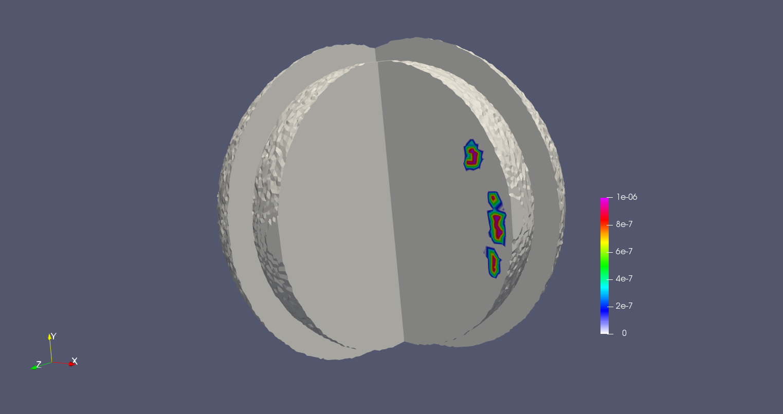
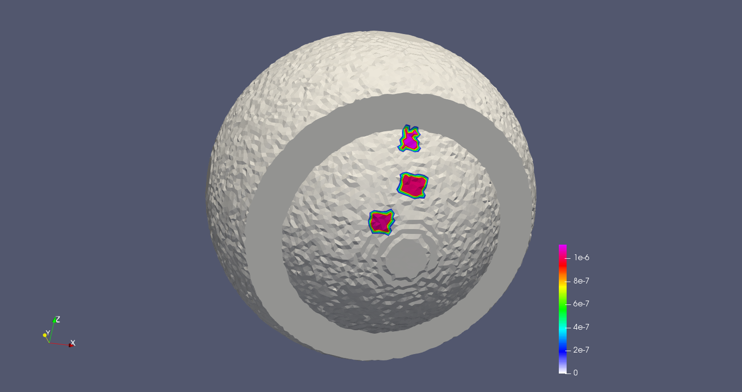
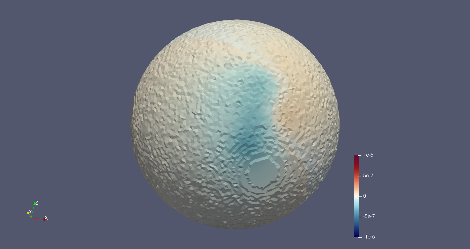
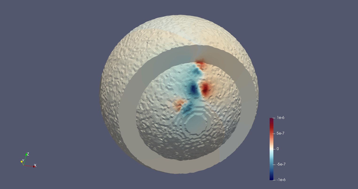
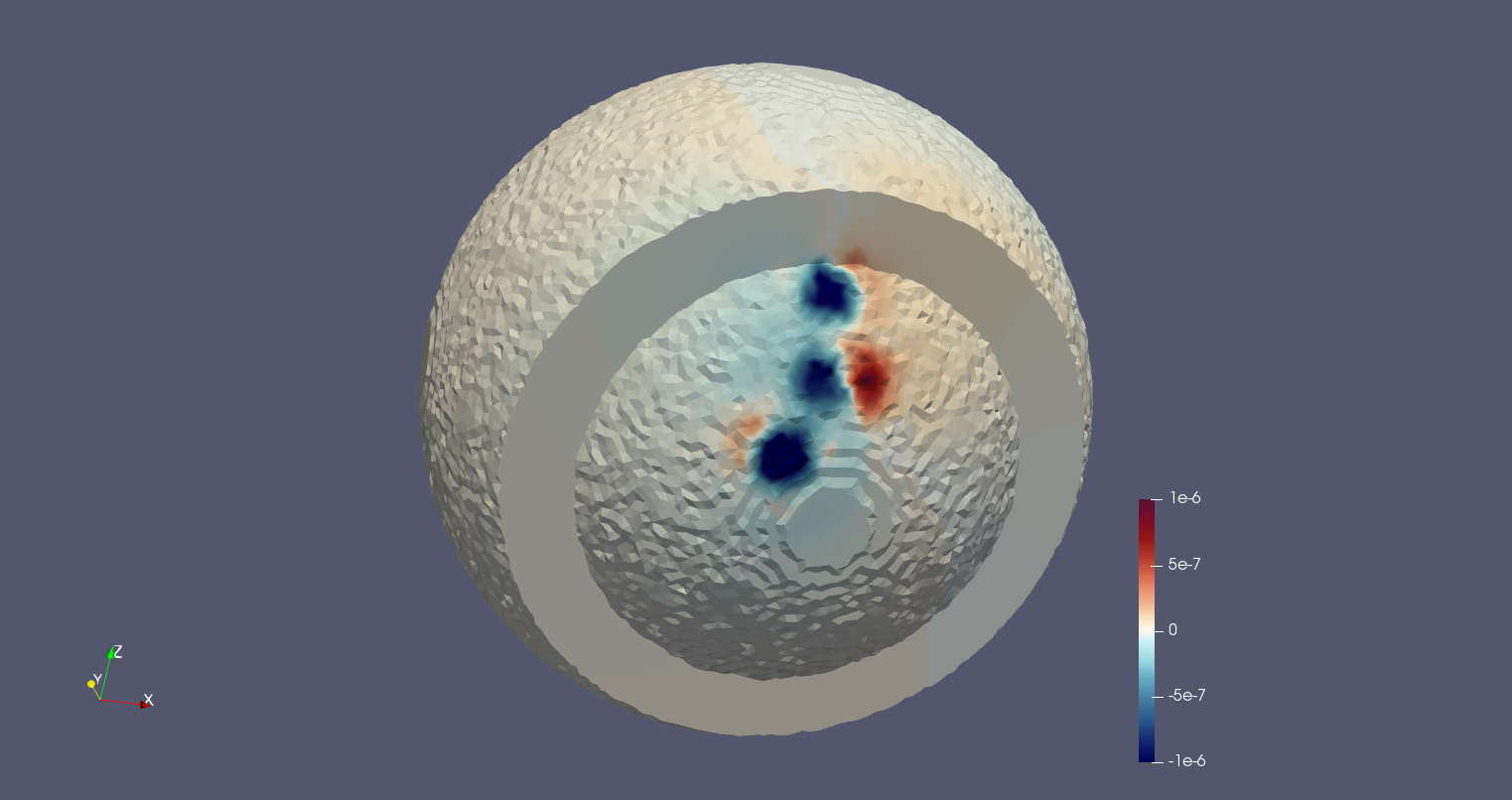
The head here is represented with a simple model, which consists of the spherical ”active” domain with the radius (see Fig. 1a) and a spherical layer representing the outer sourceless area with the radius . The conductivity of the inner domain is , and the domain can be characterized with the conductivity . The electrical sources are depicted with the support (three spots) on Fig.2 a). The support spots contain the constant currents inside it: A.
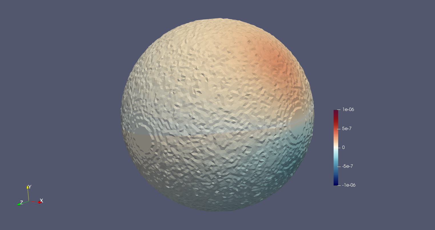
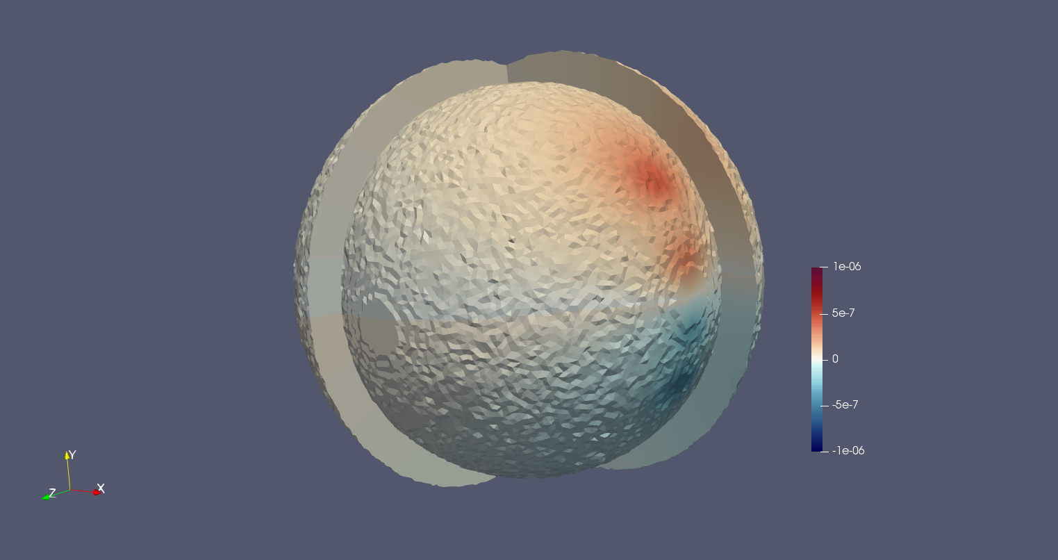
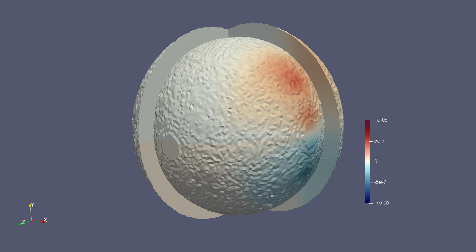
Fig.2a) and b) depict the simulated electric potential on the outer surface and the surface of the ”active” domain, respectively, while c) and d) show respectively the simulated potential on the ’brain’ surface, and the result of its reconstruction using the algorithm presented above.
The finite element mesh for the sourceless domain consists of tetrahedra and vertices. The calculation time for the Cauchy problem solver implemented with the Matlab is equal to seconds with a laptop equipped with Gb RAM and CPU Intel Core-i7 7820HQ.
 |
 |
| (a) | (b) |
 |
 |
| (c) | (d) |
4.2 Spherical model: more realistic case
Geometrically, the model under consideration in the current subsection is identical to the one in the previous subsection. It also characterized with the same conductivity distribution. The difference is in the current. First of all, the currents here are located on the interface between active and inactive domains, which is closer to the real-life encephalographic situation. Strictly speaking, the domain , in this case, should not contain its boundary surface, and it should be the opened domain. However, since the potential can be calculated via the solution of the Cauchy problem for the surface, which is arbitrary close to the surface , we were not surprised that the modelled and restored via the Cauchy problem solution potentials on an active domain surface are relatively close to each other. The following results can be seen in Fig.3.
The finite element mesh for the sourceless domain consists of tetrahedra and vertices. The calculation time for the Cauchy problem solver implemented with the Matlab is equal to seconds with a laptop equipped with Gb RAM and CPU Intel Core-i7 7820HQ.
| (a) | (b) |
| (c) | (d) |
4.3 Simplified head model based on real MRI data
The model described in this subsection is a simplified but more realistic model of the head. The mesh was constructed using the iso2mesh software [33]. Here the ”realistic” distribution of the current density over the brain surface was used.
In order to make the result more realistic, we employed two kinds of current density distributions. Fig 4 depicts the model with several ’active’ spots (support areas) of the cortex, where the current, corresponding to the spot is constant inside it. The Fig 5 shows the situation, when the current is randomely defined in each point inside the support areas (areas itself are similar to the previous case).
The finite element mesh for the sourceless domain consists of tetrahedra and vertices. The calculation time for the Cauchy problem solver implemented with the Matlab varies in the interval seconds in dependence of the current distribution used for modelling. All calculations have been provided with a laptop equipped with Gb RAM and CPU Intel Core-i7 7820HQ.
| (a) | (b) |
| (c) | (d) |
5 Conclusion
In this paper we presented an approach for Scalp-to-Cortex data mapping, based on finite elements computational scheme. The application of the approach shows great spatial resolution of the result, which is comparable to intracranial EEG (iEEG, ECoG) techniques. The method based on solving the Cauchy problem for the Laplace’s equation in homogeneous compartment and can be described as propagation of EEG data collected on the scalp through skull to the brain surface. Our numerical implementation employs the approximation of the first order finite elements on tetrahedral grids, which enables to model sophisticated irregularly shaped conductors with high precision. The method is considered as a pre-processing procedure, after which classical inverse source localization problem solvers can be applied. Notably, our algorithm successfully works with minimal soft- and hardware capabilities and does not require professional knowledge. All calculations were provided in Matlab, using only a quad-core laptop and without explicit parallelization; the computational algorithm thus has a big potential on optimization. This allows us to assume that with further improvements our method can be successfully implemented for usage with mobile platforms. Speaking of future work, we believe the solution of the Cauchy problem described in this paper can be easily adopted for source localization in magnetoencephalography. The other line of our work is to consider the same problem but with more complex algorithms in order to achieve better accuracy and compare numerically the spatial resolution of conventional EEG, ECoG and our method. Both of these areas will be certainly reflected in our future publications.
References
- [1] R.D. Pascual-Marqui, C.M. Michel, and D. Lehman. Low resolution electromagnetic tomography: a new method for localizing electrical activity in the brain. Int.J. Psychophysiol., 18:49–65, 1994.
- [2] R.D. Pascual-Marqui. Standardized low-resolution brain electromagnetic tomography (sloreta): technical details. Methods Find. Exp. Clin. Pharmacol. (Suppl. D), 24:5–12, 2002.
- [3] M. H+ m+ l+ inen and R. J. Ilmoniemi. Interpreting magnetic fields of the brain: minimum norm estimates. Medical and biological engineering and computing, 32(1):35–42, 1994.
- [4] F.H. Lin, T. Witzel, S.P. Ahlfors, S.M. Stufflebeam, J. W. Belliveau, and M.S. H+ m+ l+ inen. Assessing and improving the spatial accuracy in meg source localization by depth-weighted minimum-norm estimates. NeuroImage, 31(1):160 – 171, 2006.
- [5] S. Baillet, J. C. Mosher, and R. M. Leahy. Electromagnetic brain mapping. IEEE Signal Processing Magazine, 18(6):14–30, Nov 2001.
- [6] Roberta Grech, Tracey Cassar, Joseph Muscat, Kenneth P. Camilleri, Simon G. Fabri, Michalis Zervakis, Petros Xanthopoulos, Vangelis Sakkalis, and Bart Vanrumste. Review on solving the inverse problem in eeg source analysis. Journal of NeuroEngineering and Rehabilitation, 5(1):25, Nov 2008.
- [7] B. D. Van Veen, W. van Drongelen, M. Yuchtman, and A. Suzuki. Localization of brain electrical activity via linearity constrained minimum variance spatial filtering. IEEE Trans. Biomed. Eng., 44(9), 1997.
- [8] J.C. Mosher and R.M. Leahy. Recursive music: a framework for eeg and meg source localization. IEEE Trans. Biomed. Eng., 45(11), 1998.
- [9] Arjan Hillebrand and Gareth R. Barnes. Beamformer analysis of meg data. In Magnetoencephalography, volume 68 of International Review of Neurobiology, pages 149 – 171. Academic Press, 2005.
- [10] K. Sekihara and S.S. Nagarajan. Adaptive Spatial Filters for Electromagnetic Brain Imaging. Springer: Berlin, 2008.
- [11] Maureen Clerc and Jan Kybic. Cortical mapping by laplace–cauchy transmission using a boundary element method. Inverse Problems, 23(6):2589, 2007.
- [12] J.C. De Munck, C.H. Wolters, and M. Clerc. EEG and MEG: forward modeling, chapter Chapter 6, pages 203–272. CUP/BRRR, 2012.
- [13] Fredrik Andersson. Evaluation of numerical techniques for solving the current injection problem in biological tissues. Proceedings - International Symposium on Biomedical Imaging, 2016-June:876–880, 2016.
- [14] Bourgeois L. Convergence rates for the quasi-reversibility method to solve the cauchy problem for laplace’s equation. Inverse Problems, 22(2):413–430, 2006.
- [15] Bourgeois L. A mixed formulation of quasi-reversibility to solve the cauchy problem for laplace’s equation. Inverse Problems, 21(3):1087–1104, 2005.
- [16] Juha Latikka, Timo Kuurne, and Hannu Eskola. Conductivity of living intracranial tissues. Physics in Medicine and Biology, 46:1611–1616, 2001.
- [17] J. Sarvas. Basic mathematical and electromagnetic concepts of the biomagnetic inverse problem. Physics in Medicine and Biology, 32(1):11–22, 1987.
- [18] Plonsey R. Biomagnetic Phenomena. New York: McGraw-Hill, 1969.
- [19] M. Hämäläinen, R. Hari, R. J. Ilmoniemi, J. Knuutila, and O. V. Lounasmaa. Magnetoencephalography: theory, instrumentation, and applications to noninvasive studies of the working human brain. Rev. Modern Phys., 1993.
- [20] T.V. Zakharova, P.I. Karpov, and V.M. Bugaevskii. Localization of the activity source in the inverse problem of magnetoencefalography. Computational Mathematics and Modeling, 28(2):148–157, 2017.
- [21] Thom F. Oostendorp. The conductivity of the human skull: Results of in vivo and in vitro measurements. IEEE TRANSACTIONS ON BIOMEDICAL ENGINEERING, 47:1487–1492, 2000.
- [22] H.W. Engl and A. Leitão. A mann iterative regularization method for elliptic cauchy problems. Numerical Functional Analysis and Optimization, 22(7-8):861–884, 2001.
- [23] Frederik Berntsson and Lars Eld ’en. Numerical solution of a cauchy problem for the laplace equation. Inverse Problems, 17:839–853, 2001.
- [24] H.J. Li, X.S. Feng, J. Xiang, and P.B. Zuo. New approach for solving the inverse boundary value problem of laplace’s equation on a circle: Technique renovation of the grad-shafranov (gs) reconstruction. Journal of Geophisical Research: space physics, 118:1–7, 2013.
- [25] V. M.Klibanov, N. A. Koshev, L.I.Jingzhi, and A. G. Yagola. Numerical solution of an ill-posed cauchy problem for a quasilinear parabolic equation using a carleman weight function. Journal of Inverse and Ill-posed Problems, 2016.
- [26] Anatoly. B. Bakushinsky, Michael V. Klibanov, and Nikolaj A. Koshev. Carleman weight functions for a globally convergent numerical method for ill-posed cauchy problems for some quasilinear pdes. Nonlinear Analysis: Real World Applications, 34:201–224, 2017.
- [27] Hui Cao and Sergei V. Pereverzev. The balancing principle for the regularization of elliptic cauchy problems. Inverse Problems, 23:19431961, 2007.
- [28] Hui Cao, Michael V. Klibanov, and Sergei V. Pereverzev. A carleman estimate and the balancing principle in the quasi-reversibility method for solving the cauchy problem for the laplace equation. Inverse Problems, 25:25pp, 2009.
- [29] Jérémi Dardé, Antti Hannukainen, and Nuutti Hyvönen. An -based mixed quasi-reversibility method for solving elliptic cauchy problems. SIAM Journal on Numerical Analysis, 51:2123–2148, 2013.
- [30] M.M. Lavrentyev, V.G. Romanov, and S.P. Shishatsky. Ill-posed Problems of Mathematical Physics and Analysis. M. Nauka, 1980.
- [31] L. Bourgeois. Convergence rates for the quasi-reversibility method to solve the cauchy problem for laplace’s equation. Inverse Problems, 22:413–430, 2006.
- [32] Yu.A. Kuznetsov, O.V. Boiarkine, I.V. Kapyrin, and N.B. Yavich. Numerical analysis of a two-level preconditioner for the diffusion equation with an anisotropic diffusion tensor. Russ. J. Numer. Anal. Math. Modelling, 22(4):377–391, 2007.
- [33] http://iso2mesh.sourceforge.net/cgi-bin/index.cgi?Home.