Electron enrichment of zigzag edges of armchair–oriented graphene nano–ribbons increases their stability and induces pinning of Fermi level
Abstract
Zigzag edges of neutral armchair–oriented Graphene Nano–Ribbons show states strongly localized at those edges. They behave as free radicals that can capture electrons during processing, increasing ribbon’s stability. Thus, charging and its consequences should be investigated. Total energy calculations of finite ribbons using spin–polarized Density Functional Theory (DFT) show that ribbon’s charging is feasible. Energies for Pariser-Parr-Pople (PPP) model Hamiltonian are compatible with DFT allowing the study of larger systems. Results for neutral ribbons indicate: i) the fundamental gap of spin–polarized (non–polarized) solutions is larger (smaller) than experimental data, ii) the ground state is spin–polarized, a characteristic still not observed experimentally. Total energy of GNRs decreases with the number of captured electrons reaching a minimum for a number that mainly depends on zigzag–edges size. The following changes with respect to neutral GNRs are noted: i) the ground state is not spin–polarized, ii) fundamental gap is in-between that of spin–polarized and non–polarized solutions of neutral ribbons, iii) while in neutral ribbons valence and conduction band onsets vs. the fundamental gap, linearly and symmetrically approach mid–gap with slope 0.5, charging induces Fermi level pinning, i.e., the slopes of the valence and conduction bands being about 0.1 and 0.9, in agreement with experiment.
*Corresponding author. E-mail: enrique.louis@ua.es (Enrique Louis)
1 Introduction
The discovery of graphene has triggered a wealth of studies, both at research and production Institutions, aiming to find out applications for such a novel material [1, 2, 3]. Possible applications cover many industrial sectors requiring a panoply of properties that may justify referring to graphene as the miracle material. Requirements go from being a defect free well–defined gap material as in most applications related to nano– and micro–electronics [4, 5] up to the unavoidable functionalization of graphene if the aim is to use this material in any kind of chemical reaction (catalysis, sensors, electrochemistry, …) [1].
Controlled functionalization usually requires starting from defect–free pieces of graphene. Thus, applications in the two industrial sectors mentioned above utilize preferably perfect ribbons. In the last few years bottom–up techniques have succeeded in producing nearly perfect Graphene Nano–Ribbons (GNRs) very particularly long rectangular ribbons showing long armchair edges and short zigzag edges. We will refer to these kind of samples as armchair–oriented GNRs reserving the name Armchair Graphene Nano–Ribbons (AGNRs) to those infinitely long ribbons exclusively limited by armchair edges. Bottom–up fabrication strategies, that rely on the coupling and subsequent cyclo–dehydrogenation of suitable precursor molecules on a metallic surface (mostly gold surface)[4, 5, 6, 7, 8, 9, 10, 11, 12, 13, 14, 15, 16] have been developed up to the point that ribbons with well–defined shape and dimensions, and thus, forbidden gap, can now be produced in many laboratories [5]. In addition, transferring the GNR by means of a STM tip to a thin NaCl deposit onto the metallic substrate has allowed a reliable characterization of the electronic structure of the GNR. According to the authors of Ref.[4] the whole process neither deforms nor changes the charge–state of the ribbons.
Finite GNRs show both armchair and zigzag edges, although the GNRs commonly used in experimental studies are usually much longer along the armchair direction (i.e., armchair–oriented GNRs as defined previously). The much shorter zigzag edges of these GNRs host localized electronic states [17, 18] that are predicted to be spin polarized [19, 20, 21]. However, spin polarization at GNRs edges has still never been observed. It is argued that such localized states may induce defect formation, edge roughness, …, or interact with the substrate and, as a consequence, the study (both experimental and theoretical) of their intrinsic electronic and magnetic structures is difficult. As remarked in [22] ”the armchair edges and the region surrounding them are substantially more aromatic, compared to zigzag edges”. This is probably the origin of the much less technological difficulties that the fabrication of armchair–oriented GNRs seems to pose, as compared to zigzag–oriented GNRs. Our study shows that these molecular orbitals localized at zigzag edges of neutral GNRs may act as free radicals that can capture electrons during ribbon processing. When this happens edge reactivity vanishes and the whole ribbon’s stability increases as the behavior of total energy demonstrates.
It is obvious that, although no experimental evidence of charge capture by GNRs is yet available (see Ref.[4]), the foregoing remarks make mandatory the investigation of the charging process and its consequences. In this work, electron charging of freely suspended perfect GNRs is investigated. Calculating the total energy of a ribbon with a given size (i.e., , and being the number of carbon atoms along armchair and the zigzag directions, respectively) as a function of the amount of charge it may capture, we obtain in all cases a curve with a single minimum that gives the most probable charged state of the nano–ribbon. The total energy of small ribbons were firstly calculated both by means of spin polarized Density Functional Theory (DFT) and mean–field UHF solutions of PPP model. Since results provided by both methods are consistent, the less demanding model (PPP) was subsequently employed.
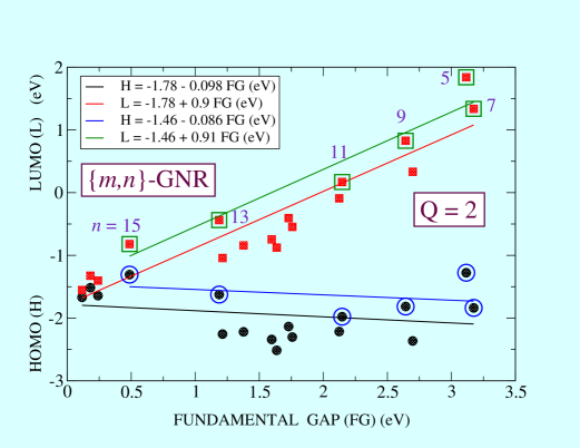
Let us finally say that thanks to GNRs charging the evolution of levels around the gap as a function of ribbon size changes completely. While in neutral ribbons valence and conduction band onsets (HOMO and LUMO levels) plotted vs. the fundamental gap, linearly and symmetrically approach the mid-gap with slope 0.5, charging breaks this symmetry inducing Fermi level pinning as the band gap decreases [23]; the slopes of the valence and conduction bands being close to about 0.1 and 0.9, to be compared with the experimental data, 0.08 and 0.92, respectively.
| DFT | PPP | PM6 | |||||
|---|---|---|---|---|---|---|---|
| Charge | m = 14 | m = 20 | m = 14 | m = 20 | m = 14 | m = 20 | |
| n = 7 | 2 | -3.32 | -3.76 | -2.82 | -3.22 | -3.68 | -4.02 |
| 4 | 1.92 | -0.90 | 3.25 | 0.61 | -0.38 | -3.03 | |
| 6 | 14.63 | 8.52 | 17.90 | 10.91 | 10.61 | 4.71 | |
| 8 | 32.10 | 23.95 | 39.65 | 27.85 | 29.13 | 17.91 | |
| n = 9 | 2 | -3.39 | -3.79 | -1.38 | -3.02 | -2.84 | -3.13 |
| 4 | 0.18 | -2.33 | 1.95 | -0.26 | -1.47 | -3.30 | |
| 6 | 11.62 | 5.58 | 14.42 | 8.65 | 8.02 | 3.51 | |
| 8 | 28.92 | 19.93 | 34.09 | 23.96 | 23.70 | 15.19 | |
| n = 15 | 2 | -3.98 | -4.88 | -1.33 | -1.33 | -5.92 | -6.20 |
| 4 | -2.81 | -4.74 | -0.81 | -2.03 | -5.48 | -6.62 | |
| 6 | 4.34 | 0.13 | 7.12 | 3.24 | 0.59 | -3.31 | |
| 8 | 18.15 | 10.26 | 21.91 | 14.45 | 12.19 | 5.12 | |
2 Methods and numerical procedures
Calculations have been carried out on freely suspended -GNRs, being the number of carbon atoms along the armchair direction and the number corresponding to the zigzag edge. Since most of our ribbons show , we will associated to their lengths and to their width. Actual size is given by:
being a typical C-C bond length that we take as 1.41 . The total number of carbon atoms present in the GNR is . The chosen ribbons widths were = 7, 9, 13, 15 and 19, while the largest length was = 100 that corresponds approximately to 210.1 (only for the narrower ribbons). Dangling bonds of all carbon atoms at the ribbon edges have been bonded to hydrogen so that all carbon atoms have a single non–saturated -like orbital. Largest ribbons were formed by around 1500 atoms. Extra electrons were always added in pairs to preclude spin polarized ground states. Actually, we carried out calculations for Q = 2, 4, 6 and 8. Calculations were carried out by means of two semiempirical methods, namely, PPP and PM6. For the smallest systems spin polarized DFT calculations have also been carried out.
Ab initio calculations were done with the Gaussian09 package [30]. As regards the exchange-correlation functional, the widely accepted B3LYP[24, 25, 26, 27] functional in combination with the 6-31+G*[28, 29] basis set has been used. It incorporates diffuse functions around carbon atoms to get a better description of delocalized orbitals of charged systems. Geometries of all ribbons have been optimized.
PM6 [31] is the latest parametrization of the NDDO method [32], which has been modified adopting Voityuk’s core-core diatomic interaction parameters together with the method of parameter optimization. Parametrization including 70 elements and the heats of formation for a subset of 1,373 compounds (with only H, C, N, O, F, P, S, Cl and Br elements) give an average unsigned error (4.4 kcal/mol) better than alternative semiempirical methods, such as RM1(5.0), AM1(10.0) and PM3(6.3), or the HF/6-31G*(7.4) and B3LYP/6-31G*(5.2). The geometry of all systems was also optimized.
Finally, PPP Hamiltonian was solved within Unrestricted Hartree-Fock approximation using parameters fitted to the electronic structure of small PAH (see [33] and [34]). Note that the fact that this Hamiltonian includes a single orbital per site should not be a major drawback as in graphene all carbon atoms have a single non–saturated –like orbital.
3 Results and Discussion
Probably forced by the lack of experimental confirmation of the existence of magnetism in the zigzag edges of GNRs, other theoretical studies of GNR have discarded unrestricted spin polarized solutions from the very beginning [35, 36]. This is so despite of the fact that mono–determinantal unrestricted solutions are spin polarized no matter the chosen framework, model Hamiltonians solved within Unrestricted Hartree-Fock, or the most sophisticated ab initio DFT and GW approaches [4, 19, 20, 21]. In the following we discuss an alternative way to reconcile the experimental evidence with calculations.
3.1 Localized states at the zigzag edges
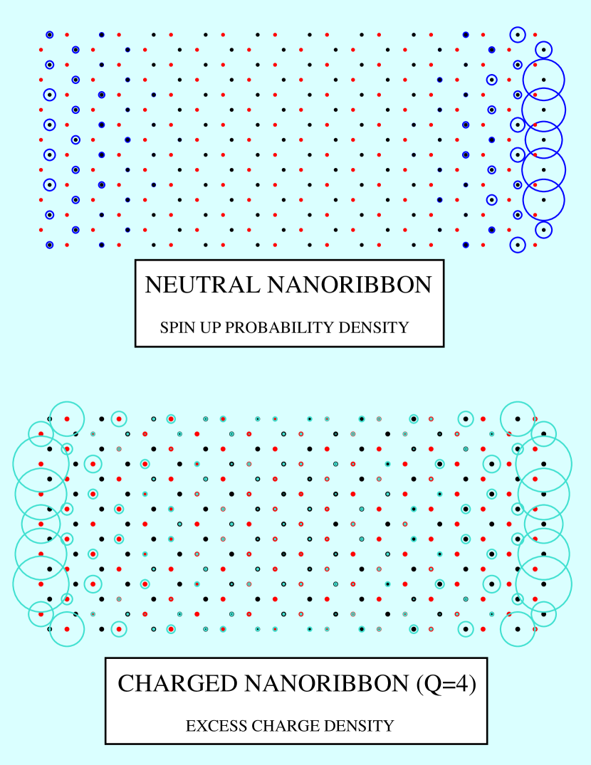
As pointed out in the Introduction, the zigzag edges of neutral GNRs host unpaired electrons described by localized states that act as radical centers ready to capture charge. This is clearly illustrated in Fig.1 which shows that the staggered magnetization in a neutral {20,15}-GNR is mostly localized at the two zigzag edges of the ribbon. In the Figure only the up component of the spin is shown, the down component is derived from it by exchanging zigzag sides. Spin polarization illustrates the breaking of the specular symmetry with respect to the plane perpendicular to the long axis of the ribbon that splits it in two identical parts. If electrons are incorporated to the ribbon, no matter how they were captured, the ribbon ground state becomes non–magnetic and the original symmetry of the ribbon becomes restored (see lower panel of Fig.1). Both empty and occupied localized states lie around the Fermi level. Changes in the total number of electrons have therefore important consequences on the electronic structure around the gap. Let us show two examples of the kind of states involved in the chemical deactivation via electron enrichment of a typical GNR.
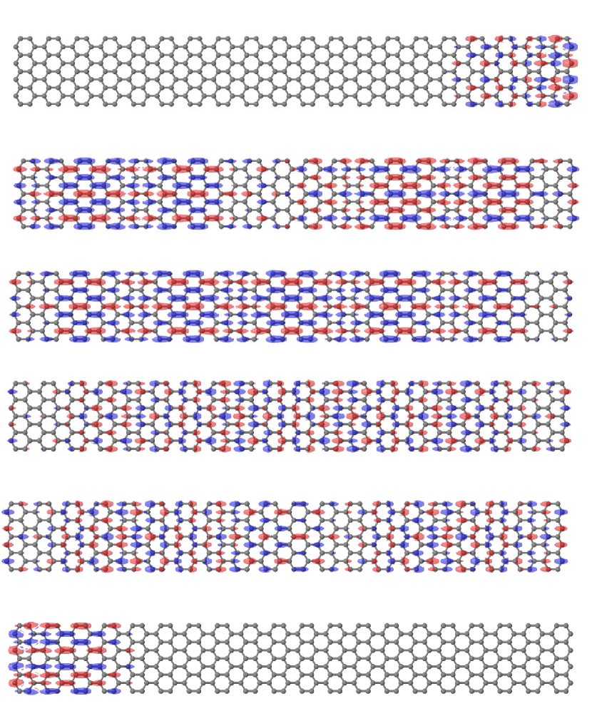
The characteristics of neutral spin polarized GNRs are illustrated by the spin densities of the six molecular orbitals around the Fermi level (see Fig. 2) in a neutral {40,9}-GNR. First and sixth orbitals (starting from the lowermost level) are strongly localized at the zigzag edges of the ribbon. The Fermi level lies between the 3rd and fourth orbitals, its energy being -3.456 eV. Molecular orbital energies calculated by means of UHF-PPP are: -5.68, -5.62, -5.477, -1.453, -1.31 and -1.25 eV. As already remarked, spin down orbitals are obtained from the spin up orbitals by exchanging sides. As a final result, antiferromagnetic correlations between zigzag edges exist. Instead, extended orbitals are either symmetric or antisymmetric respect the specular plane mentioned in the previous paragraph (see 2nd up to 5th orbitals in Fig.2).
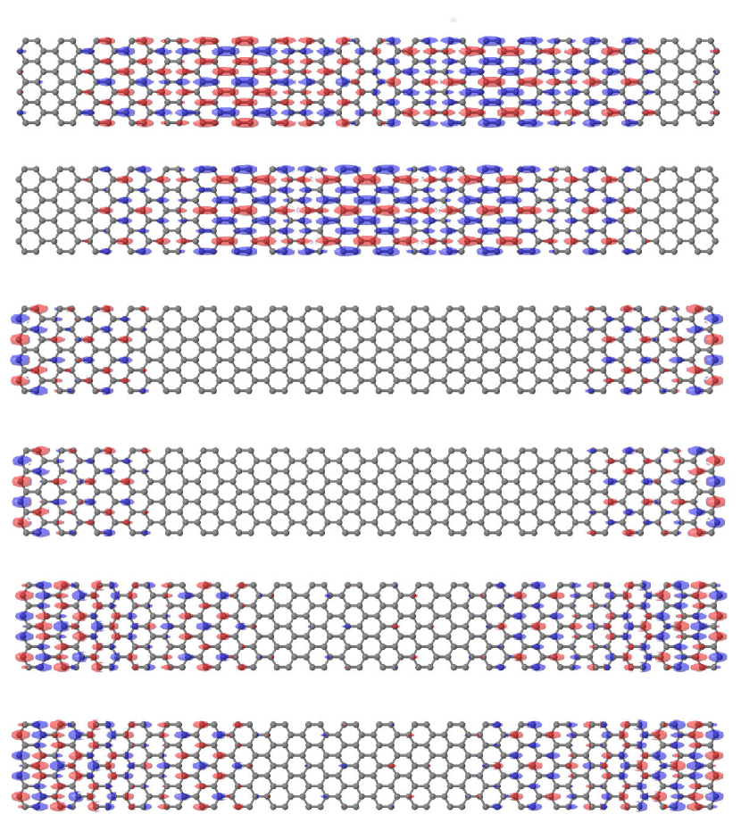
The recovery of the full symmetry induced by charging the ribbons is nicely illustrated in Fig. 3. This Figure shows the spin densities of six spin up molecular orbitals around the Fermi level of a {40,9}-GNR charged with Q = 2. Orbital energies, as calculated by means of UHF-PPP, are: -3.73, -3.73, -2.14, -2.14, -0.41 and -0.067 eV. Third and fourth orbitals are strongly localized at the zigzag edges of the ribbon and fully occupied since the Fermi level lies between the 4th and fifth orbitals. The original symmetry of the graphene lattice becomes all fully restored because all states no matter extended or localized are now symmetric or antisymmetric. As a consequence, both and are null (non-magnetic configuration).
3.2 Charging stabilizes GNRs
At this point the issue is whether charging reduces the nano-ribbon total energy and, thus, increases its stability. Calculated total energies (all in eV) of small -GNRs by means of DFT, UHF-PPP and PM6, are reported in Tables 1 and 2. As shown in the Tables, whenever the excess charge is not too high, charged ribbons are more stable than neutral ribbons. This result, which is the core of the present work, holds for the three theoretical methods used here. In addition it is noted that DFT energies are always smaller than those obtained with the UHF solution of the model PPP Hamiltonian. Instead, no conclusion can be derived from a comparison of DFT and MP6 results. Anyway, the main result is very robust as the three theoretical methods used here always agree at a qualitative and, in some cases, even at a semi–quantitative level: the total energy of GNR diminishes upon ribbon’s charging reaching a minimum at a charging level that depends on ribbon’s length and width. Thereafter, the energy increases monotonically.
| Charge | = 20 | = 40 | = 60 | = 80 | = 100 | |
|---|---|---|---|---|---|---|
| = 7 | 2 | -3.22 | -3.59 | -3.67 | -3.71 | -3.72 |
| 4 | 0.61 | -2.73 | -3.79 | -4.33 | -4.69 | |
| 6 | 10.91 | 1.0 | -1.5 | -3.06 | -4.0 | |
| 8 | 27.85 | 9.66 | 3.55 | 0.21 | -1.74 | |
| = 9 | 2 | -3.02 | -3.33 | -3.42 | -3.41 | 3.45 |
| 4 | -0.26 | -3.25 | -4.26 | -4.74 | -4.78 | |
| 6 | 8.65 | 0.40 | -2.71 | -4.21 | -4.25 | |
| 8 | 23.96 | 7.96 | -1.63 | -1.62 | -1.67 | |
| = 13 | 2 | -3.8 | -1.87 | -1.93 | -1.96 | |
| 4 | -2.18 | -4.05 | -4.59 | -4.81 | ||
| 6 | 4.22 | -2.39 | -4.97 | -5.95 | ||
| 8 | 16.71 | 3.20 | -2.16 | -4.93 | ||
| = 15 | 2 | -3.51 | -1.51 | -1.57 | -1.84 | |
| 4 | -2.17 | -3.49 | -4.38 | -4.38 | ||
| 6 | 3.24 | -2.41 | -4.53 | -5.57 | ||
| 8 | 14.45 | 2.52 | -2.35 | -4.91 | ||
| = 19 | 2 | -4.07 | -2.43 | -2.56 | -2.62 | |
| 4 | -4.07 | -4.04 | -2.56 | -5.59 | ||
| 6 | 1.04 | -3.08 | -5.36 | -6.81 | ||
| 8 | 10.09 | 0.49 | -3.62 | -6.81 |
 |
 |
 |
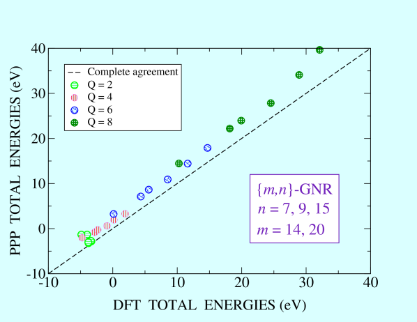
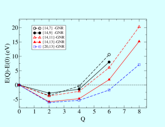
Aiming to illustrate in a pictorial way the agreement of DFT and HF-PPP results, Figure 4 depicts the energies of charged -GNRs referred to that of the respective neutral ribbons. The results correspond to ribbons charged with Q = 2, 4, 6, 8 and sizes = 14 and 20 and = 7, 9 and 15. (see Table 1). The straight line corresponds to complete agreement, that is, all DFT energies coinciding with all UHF-PPP energies. Note that the numerical data are not far from this ideal line validating the use of HF-PPP for the calculation of total energies, fundamental gaps, … etc. Once we have confirmed the consistency between results provided by different methods, much larger systems have been exclusively calculated using the UHF-PPP scheme. Table 2 provides the corresponding results. Charge at which energy is minimal in each case is shown in bold characters in both Tables 1 and 2.
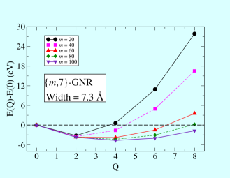
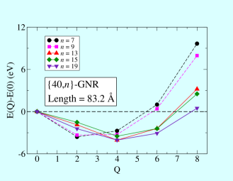
Numerical data compiled in both Tables are better analyzed after a graphical representation that is given by Figure 5. In the upper panel results for {,7}-GNR and five lengths = 20, 40, 60, 80 and 100 have been represented. It can be observed that the minimum shifts from Q = 2 to Q = 4 for the larger GNRs. Although results for even larger ribbons are difficult to obtain, we believe that four is the maximum number of electrons that a = 7 GNR admits. Notice that a non–completely screened Coulomb interaction between electrons at opposite zigzag edges makes the convergence of energy vs. length (that is, ) very slow. The middle panel depicts some results obtained with the semiempirical PM6 method. Energy minima for short GNRs are obtained for Q =2. Nevertheless, the total number of electrons stabilizing a zigzag edge should increase with its size. This is confirmed by the lower panel showing a stabilization with four electrons for {40,13}, {40,15} and {40,19} ribbons. Summarizing, the number of electrons stabilizing a zigzag edge of a given width goes to a constant value for very large GNRs. On the other hand, the number of extra charge that admits a zigzag edge is more or less proportional to its width.
 |
 |
3.3 Fundamental gap of neutral and charged GNRs versus ribbon width and length
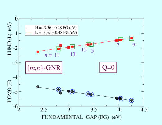
The upper panel of Figure 6 depicts results for the HOMO (circles) and LUMO (squares) energy levels versus the fundamental gap (FG) for neutral GNRs of several widths and lengths. Results, obtained with HF-PPP, correspond to widths of = 5, 7 and 9 and lengths of = 20, 40, 60 and 80, and widths of = 11, 13, 15 and 19 and lengths of = 20 and 40. Empty symbols correspond to ribbons of fixed length ( = 20). Both HOMO and LUMO levels show a monotonic dependence on ribbon’s FG and a very irregular dependence on ribbon’s width. The straight lines fitted to the numerical results are shown in the inset. The slopes are very close to S = 0.5 (valence and conduction band, respectively), as expected in a system with electron-hole symmetry [23].
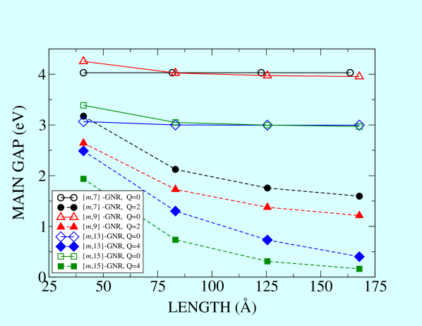
Recent experiments [23] on armchair oriented GNRs of several widths deposited on Au(1,1,1) surface report results at variance with the symmetric case illustrated in the upper panel of Figure 6. The authors presented results for the valence and conduction band onsets versus the fundamental gap (FG) that for large gap values (FG 1.7 eV) vary linearly with ribbon’s FG with slopes of approximately 0.5, as found in a symmetric system. However, for FG 1.7 eV , the valence band shows Fermi level pinning as the fundamental band gap decreases. The slope of the fitted straight line being slightly smaller than 0.1. At the same time, the fundamental gap monotonically diminishes with both and (see Fig.5 of Ref.[23] and the dashed curves of our Fig.7). We have been able to obtain here similar results for freely suspended ribbons as long as they are charged with two or more electrons. Our results are depicted in the lower panel of Figure 6. They correspond to the same set of ribbons that was employed for the neutral case. The straight lines fitted to the numerical results are shown in the inset. When all numerical results are included in the fittings, the slopes are -0.098 and 0.9 for HOMO and LUMO levels, respectively, not far from the results reported in Ref. [23] namely, -0.08 0.05 and 0.92 0.05. Results do not change much if fittings are carried out including only data for ribbons of length 40.9 Å. These slopes were obtained from fittings of data with FG 3.2 eV, higher than the experimental value of 1.7 eV, a discrepancy likely due to the mean field approach adopted here. On the other hand, the results shown in the lower panel of Fig. 6 reveal a monotonic dependence of the two band onsets on the ribbon’s width, as opposed to what we obtained for neutral ribbons. This is further illustrated by Fig. 7 which shows that the main gap of charged GNRs smoothly depends on both length and width.
As a summary of this paragraph we can say that a wide gap in neutral armchair oriented GNRs is only obtained if a spin polarized formalism allowing spin symmetry breaking is used, something not yet fully supported by experiments. Instead, gaps in non–polarized ribbons are very small no matter which method is used in the calculations. The present results indicate that charging has several appealing effects: i) the ground state of the charged ribbons is non–polarized, ii) gaps are substantially smaller than those found in spin polarized solutions, although are larger than the experimental ones, and iii) valence and conduction bands are no longer symmetrically placed with respect to the Fermi level. We believe that these results are enough to justify the following of the route initiated in this work as at present there is no alternative theory that can explain the experimental results of Ref. [23].
4 Concluding Remarks
Zigzag edges of graphene nanoribbons, in particular armchair oriented GNRs, host localized electronic states of opposite spin at both ribbon edges. Consequently, the most sophisticated quantum chemistry tools now available, predict a spin polarized ground state. However, spin polarized edge states have not yet been observed experimentally. This dramatic disagreement is usually ascribed to the high susceptibility of these states to develop edge defects and roughness or to some indefinite interaction with the supporting substrate. In this work, taking for granted the predicted spin polarized character of zigzag edges in GNRs and the reliability of the experimental studies that aiming to find any traces of spin polarization have failed, we undertook the task of seeking alternative effects that may obscure or eliminate that spin polarization. Taking note of the fact that some of the so called edge states may be empty, we consider the possibility that adding extra charge to the ribbons might contribute to increase their stability. Our work, then, was focused on this issue. All calculations, no matter which method we used, gave a curve of total energy versus extra charge that showed a minimum at a value of the charge that varied with ribbon’s width and length. Width dependence of the fundamental gap reveals valence bands which show Fermi level pinning as the fundamental band gap decreases, in agreement with recent experimental data and at variance with the symmetry characteristic of neutral ribbons. It is pertinent to remark that it would be interesting to investigate the conductance of charged ribbons along the lines, for instance, of a recently published work [36]. As regards the actual values of the forbidden gap it is noted that, in neutral ribbons the gap of spin polarized gaps is larger than what has been observed up to now, the opposite occurs in non-polarized. Instead, charged ribbons show a forbidden gap in-between those two, closer to the experimental data.
Acknowledgments
This work has been partially supported by the Spanish ”Ministerio de Ciencia, Innovación y Universidades” (Grants FIS2015-64222-C2-1-P, FIS2015-64222-C2-2-P, MAT2016-77742-C2-2-P and AYA2015-66899-C2-2-P), and the Universidad de Alicante is gratefully acknowledged.
References
-
[1]
A. Eftekhari, H. Garcia,
The
necessity of structural irregularities for the chemical applications of
graphene, Materials Today Chemistry 4 (2017) 1 – 16.
doi:10.1016/j.mtchem.2017.02.003.
URL http://www.sciencedirect.com/science/article/pii/S24685%19417300034 -
[2]
P. Solis-Fernandez, M. Bissett, H. Ago,
Synthesis, structure and
applications of graphene-based 2d heterostructures, Chem. Soc. Rev. 46
(2017) 4572–4613.
doi:10.1039/C7CS00160F.
URL http://dx.doi.org/10.1039/C7CS00160F -
[3]
Y. Zhu, H. Ji, H.-M. Cheng, R. S. Ruoff,
Mass production and industrial
applications of graphene materials, National Science Review 5 (1) (2018)
90–101.
doi:10.1093/nsr/nwx055.
URL http://dx.doi.org/10.1093/nsr/nwx055 -
[4]
S. Wang, L. Talirz, C. A. Pignedoli, X. Feng, K. Müllen, R. Fasel,
P. Ruffieux, Giant edge state splitting at atomically precise graphene zigzag edges,
Nature Communications 7 (2016) 11507.
URL http://dx.doi.org/10.1038/ncomms11507http://10.0.4.14/ncomms11507https://www.nature.com/articles/ncomms11507{#}supplementary-information -
[5]
T. Leopold, R. Pascal, F. Roman,
On-surface synthesis of atomically precise graphene nanoribbons,
Advanced Materials 28 (29) (2016) 6222–6231.
doi:10.1002/adma.201505738.
URL https://onlinelibrary.wiley.com/doi/abs/10.1002/adma.20%1505738 -
[6]
W.-X. Wang, M. Zhou, X. Li, S.-Y. Li, X. Wu, W. Duan, L. He,
Energy gaps of atomically precise armchair graphene sidewall nanoribbons,
Phys. Rev. B 93 (2016) 241403.
doi:10.1103/PhysRevB.93.241403.
URL https://link.aps.org/doi/10.1103/PhysRevB.93.241403 -
[7]
W. Xu, T.-W. Lee, Recent progress
in fabrication techniques of graphene nanoribbons, Mater. Horiz. 3 (2016)
186–207.
doi:10.1039/C5MH00288E.
URL http://dx.doi.org/10.1039/C5MH00288E -
[8]
C.-N. Yeh, P.-Y. Lee, J.-D. Chai,
Electronic and Optical Properties of the Narrowest Armchair Graphene Nanoribbons
Studied by Density Functional Methods,
Australian Journal of Chemistry 69 (9) (2016) 960–968.
URL https://doi.org/10.1071/CH16187 -
[9]
C.-S. Wu, J.-D. Chai, Electronic
properties of zigzag graphene nanoribbons studied by tao-dft, Journal of
Chemical Theory and Computation 11 (5) (2015) 2003–2011.
doi:10.1021/ct500999m.
URL https://doi.org/10.1021/ct500999m -
[10]
S. Li, C. K. Gan, Y.-W. Son, Y. P. Feng, S. Y. Quek,
Anomalous length-independent frontier resonant transmission peaks in armchair
graphene nanoribbon molecular wires,
Carbon 76 (2014) 285 – 291.
doi:10.1016/j.carbon.2014.04.079.
URL http://www.sciencedirect.com/science/article/pii/S00086%22314004114 -
[11]
L. Talirz, H. Söde, T. Dumslaff, S. Wang, J. R. Sanchez-Valencia, J. Liu,
P. Shinde, C. A. Pignedoli, L. Liang, V. Meunier, N. C. Plumb, M. Shi,
X. Feng, A. Narita, K. Müllen, R. Fasel, P. Ruffieux,
On-surface synthesis and characterization of 9-atom wide armchair graphene nanoribbons,
ACS Nano 11 (2) (2017) 1380–1388, pMID: 28129507.
doi:10.1021/acsnano.6b06405.
URL https://doi.org/10.1021/acsnano.6b06405 -
[12]
Y.-C. Chen, D. G. de Oteyza, Z. Pedramrazi, C. Chen, F. R. Fischer, M. F. Crommie,
Tuning the band gap of graphene nanoribbons synthesized from molecular precursors,
ACS Nano 7 (7) (2013) 6123–6128, pMID: 23746141.
doi:10.1021/nn401948e.
URL https://doi.org/10.1021/nn401948e -
[13]
L. Talirz, H. Söde, J. Cai, P. Ruffieux, S. Blankenburg, R. Jafaar, R. Berger,
X. Feng, K. Müllen, D. Passerone, R. Fasel, C. A. Pignedoli,
Termini of bottom-up fabricated
graphene nanoribbons, Journal of the American Chemical Society 135 (6)
(2013) 2060–2063, pMID: 23350872.
doi:10.1021/ja311099k.
URL https://doi.org/10.1021/ja311099k -
[14]
P. Ruffieux, J. Cai, N. C. Plumb, L. Patthey, D. Prezzi, A. Ferretti,
E. Molinari, X. Feng, K. Müllen, C. A. Pignedoli, R. Fasel,
Electronic structure of atomically
precise graphene nanoribbons, ACS Nano 6 (8) (2012) 6930–6935, pMID:
22853456.
doi:10.1021/nn3021376.
URL https://doi.org/10.1021/nn3021376 - [15] M. Koch, F. Ample, C. Joachim, L. Grill, Voltage-dependent conductance of a single graphene nanoribbon, Nature Nanotechnology 7 (2012) 713. URL http://dx.doi.org/10.1038/nnano.2012.169https://www.nature.com/articles/nnano.2012.169
-
[16]
P. B. Bennett, Z. Pedramrazi, A. Madani, Y.-C. Chen, D. G. de Oteyza, C. Chen,
F. R. Fischer, M. F. Crommie, J. Bokor,
Bottom-up graphene nanoribbon
field-effect transistors, Applied Physics Letters 103 (25) (2013) 253114.
doi:10.1063/1.4855116.
URL https://doi.org/10.1063/1.4855116 -
[17]
S. Hauptmann,
The aromatic sextet: Von e. clar; john wiley & sons ltd, london, new york,
sydney, toronto 1972; 128 seiten mit zahlreichen formelbildern; format 13 ×
20 cm; broschiert £ 1, 50,
Zeitschrift für Chemie 13 (5) (1973) 200–200.
doi:10.1002/zfch.19730130531.
URL https://onlinelibrary.wiley.com/doi/abs/10.1002/zfch.19%730130531 -
[18]
M. Solà, Forty years of Clar’s aromatic
-sextet rule, Frontiers in chemistry 1 (2013) 22.
doi:10.3389/fchem.2013.00022.
URL https://www.ncbi.nlm.nih.gov/pubmed/24790950https://www.ncbi.nlm.nih.gov/pmc/PMC3982536/ -
[19]
L. Yang, C.-H. Park, Y.-W. Son, M. L. Cohen, S. G. Louie,
Quasiparticle
energies and band gaps in graphene nanoribbons, Phys. Rev. Lett. 99 (2007)
186801.
doi:10.1103/PhysRevLett.99.186801.
URL https://link.aps.org/doi/10.1103/PhysRevLett.99.186801 -
[20]
O. V. Yazyev,
Emergence of
magnetism in graphene materials and nanostructures, Reports on Progress in
Physics 73 (5) (2010) 056501.
doi:10.1088/0034-4885/73/5/056501.
URL https://doi.org/10.1088%2F0034-4885%2F73%2F5%2F0565%01 -
[21]
M. Golor, C. Koop, T. C. Lang, S. Wessel, M. J. Schmidt,
Magnetic
correlations in short and narrow graphene armchair nanoribbons, Phys. Rev.
Lett. 111 (2013) 085504.
doi:10.1103/PhysRevLett.111.085504.
URL https://link.aps.org/doi/10.1103/PhysRevLett.111.085504 -
[22]
A. D. Zdetsis, E. N. Economou,
A pedestrian approach to the aromaticity of graphene and nanographene:
Significance of huckel’s (4n+2) electron rule,
The Journal of Physical Chemistry C 119 (29) (2015) 16991–17003.
doi:10.1021/acs.jpcc.5b04311.
URL https://doi.org/10.1021/acs.jpcc.5b04311 -
[23]
N. Merino-Díez, A. Garcia-Lekue, E. Carbonell-Sanromà, J. Li, M. Corso,
L. Colazzo, F. Sedona, D. Sánchez-Portal, J. I. Pascual, D. G. de Oteyza,
Width-dependent band gap in
armchair graphene nanoribbons reveals fermi level pinning on au(111), ACS
Nano 11 (11) (2017) 11661–11668, pMID: 29049879.
doi:10.1021/acsnano.7b06765.
URL https://doi.org/10.1021/acsnano.7b06765 - [24] A. D. Becke, Density-functional exchange-energy approximation with correct asymptotic behavior, Phys. Rev. A 38 (6) (1988) 3098–3100.
-
[25]
C. Lee, W. Yang, R. G. Parr,
Development of the
colle-salvetti correlation-energy formula into a functional of the electron
density, Phys. Rev. B 37 (1988) 785–789.
doi:10.1103/PhysRevB.37.785.
URL http://link.aps.org/doi/10.1103/PhysRevB.37.785 -
[26]
A. D. Becke, Density functional thermochemistry. iii. the role of exact exchange,
J. Chem. Phys. 98 (7) (1993) 5648–5652.
doi:10.1063/1.464913.
URL http://aip.scitation.org/doi/abs/10.1063/1.464913 -
[27]
P. J. Stephens, F. J. Devlin, C. F. Chabalowski, M. J. Frisch,
Ab initio calculation of vibrational absorption and circular dichroism
spectra using density functional force fields,
J. Phys. Chem. 98 (45) (1994) 11623–11627.
doi:10.1021/j100096a001.
URL http://dx.doi.org/10.1021/j100096a001 - [28] P. C. Hariharan, J. A. Pople, The influence of polarization functions on molecular orbital hidrogenation energies, Theor. Chim. Acta 28 (1973) 213.
-
[29]
T. Clark, J. Chandrasekhar, G. W. Spitznagel, P. V. R. Schleyer,
Efficient diffuse function-augmented basis sets for anion calculations.
iii. the 3-21+g basis set for first-row elements, Li–F,
J. Comput. Chem. 4 (3) (1983) 294 – 301.
doi:10.1002/jcc.540040303.
URL http://dx.doi.org/10.1002/jcc.540040303 - [30] M. J. Frisch, G. W. Trucks, H. B. Schlegel, G. E. Scuseria, M. A. Robb, J. R. Cheeseman, G. Scalmani, V. Barone, B. Mennucci, G. A. Petersson, H. Nakatsuji, M. Caricato, X. Li, H. P. Hratchian, A. F. Izmaylov, J. Bloino, G. Zheng, J. L. Sonnenberg, M. Hada, M. Ehara, K. Toyota, R. Fukuda, J. Hasegawa, M. Ishida, T. Nakajima, Y. Honda, O. Kitao, H. Nakai, T. Vreven, J. A. Montgomery, Jr., J. E. Peralta, F. Ogliaro, M. Bearpark, J. J. Heyd, E. Brothers, K. N. Kudin, V. N. Staroverov, R. Kobayashi, J. Normand, K. Raghavachari, A. Rendell, J. C. Burant, S. S. Iyengar, J. Tomasi, M. Cossi, N. Rega, J. M. Millam, M. Klene, J. E. Knox, J. B. Cross, V. Bakken, C. Adamo, J. Jaramillo, R. Gomperts, R. E. Stratmann, O. Yazyev, A. J. Austin, R. Cammi, C. Pomelli, J. W. Ochterski, R. L. Martin, K. Morokuma, V. G. Zakrzewski, G. A. Voth, P. Salvador, J. J. Dannenberg, S. Dapprich, A. D. Daniels, O. Farkas, J. B. Foresman, J. V. Ortiz, J. Cioslowski, D. J. Fox, Gaussian 09 revision d.01, gaussian Inc. Wallingford CT (2009).
-
[31]
J. Stewart, Optimization of
parameters for semiempirical methods v: Modification of nddo approximations
and application to 70 elements, Journal of Molecular Modeling 13 (12) (2007)
1173–1213.
doi:10.1007/s00894-007-0233-4.
URL http://dx.doi.org/10.1007/s00894-007-0233-4 - [32] M. J. S. Dewar, W. Thiel, Ground states of molecules. 38. the mndo method. approximations and parameters, J. Am. Chem. Soc. 99 (1977) 4899.
- [33] J. A. Vergés, E. SanFabián, G. Chiappe, E. Louis, Fit of pariser-parr-pople and hubbard model hamiltonians to charge and spin states of polycyclic aromatic hydrocarbons, Physical Review B 81 (8) (2010) 085120, pT: J; TC: 6; UT: WOS:000275053300047.
-
[34]
G. Chiappe, E. Louis, E. San-Fabián and J. A. Vergés,
Can model Hamiltonians describe the electron–electron
interaction in -conjugated systems?: PAH and graphene,
Journal of Physics: Condensed Matter 27 (46) (2015) 463001.
URL http://stacks.iop.org/0953-8984/27/i=46/a=463001 -
[35]
A. D. Zdetsis, E. Economou,
Rationalizing and reconciling energy gaps and quantum confinement in narrow
atomically precise armchair graphene nanoribbons,
Carbon 116 (2017) 422 – 434.
doi:10.1016/j.carbon.2017.02.006.
URL http://www.sciencedirect.com/science/article/pii/S0008622317301240 -
[36]
J. A. Vergés, G. Chiappe, E. San-Fabián, E. Louis,
Conductance through the armchair graphene nanoribbons 9-agnr: Strong dependence on contact to leads,
Phys. Rev. B 98 (2018) 155415.
doi:10.1103/PhysRevB.98.155415.
URL https://link.aps.org/doi/10.1103/PhysRevB.98.155415