(“Oops! Had the silly thing in reverse”)—Optical injection attacks in through LED status indicators
Abstract
It is possible to attack a computer remotely through the front panel LEDs. Following on previous results that showed information leakage at optical wavelengths, now it seems practicable to inject information into a system as well. It is shown to be definitely feasible under realistic conditions (by infosec standards) of target system compromise; experimental results suggest it further may be possible, through a slightly different mechanism, even under high security conditions that put extremely difficult constraints on the attacker. The problem is of recent origin; it could not have occurred before a confluence of unrelated technological developments made it possible. Arduino-type microcontrollers are involved; this is an Internet of Things (IoT) vulnerability. Unlike some previous findings, the vulnerability here is moderate—at present—because it takes the infosec form of a classical covert channel. However, the architecture of several popular families of microcontrollers suggests that a Rowhammer-like directed energy optical attack that requires no malware might be possible. Phase I experiments yielded surprising and encouraging results; a covert channel is definitely practicable without exotic hardware, bandwidth approaching a Mbit/s, and the majority of discrete LEDs tested were found to be reversible on GPIO pins. Phase II experiments, not yet funded, will try to open the door remotely.
I The Nature of the Vulnerability
Light emitting diodes (LEDs) are reversible; when illuminated by an outside source, they act like tiny solar cells and produce an electric current. They can be used as photodiode light sensors. The fact has been known since at least the nineteen-seventies and is occasionally useful [1, 2, 3, 4, 5, 6]. Modern microcontrollers—those small microprocessors used for all kinds of things that aren’t generally thought of as ‘computers’—are highly integrated systems-on-a-chip (SoC) that directly incorporate most of the peripheral devices—such as memory, network interfaces, and digital-to-analogue converters—that used to be separate chips interfaced directly with the address and data buses of the central processing unit (CPU). Consequently, new microcontrollers tend to expose instead a large number of general purpose input/output (GPIO) pins to the outside world for the purpose of reading buttons and switches, turning on LEDs, controlling small motors, or connecting to a speaker. GPIO pins are highly adaptable; any GPIO can be a digital input or output, and some of them can be analogue inputs or outputs. They can be pulse width modulation (PWM) sources, or serial channel clock and data signals. The behaviour of any given GPIO pin at any particular time is controlled by software running on the CPU [7].
One other thing about GPIO pins: these days they have programmable pull-up or pull-down resistors—a great convenience to hardware designers.111Pull-up resistors—and in some cases pull-down resistors—are needed for reading switches or buttons reliably in the real world, and sometimes when resources on the circuit board are shared. In the old days, it was necessary to install components on the board, taking space and driving up costs. Now the designer can do all it in software. (And software can be changed.)

Hardware designers have lots of GPIO pins to use, and use them for all sorts of things, including LEDs. The third and final piece of the puzzle (see Table I) was the introduction of ultra high-brightness LEDs [8]. These are highly efficient, so obviate the need for external current-buffering transistors. They also—although the phenomenon has not really been studied by anyone—seemingly have at least as high a responsivity to external light sources as older discrete LEDs did (see Figure 1). The combination is deadly. Reprogrammable GPIO pins connected to LEDs are an unlocked door through which hackers can send information in both directions.
This is a preliminary report of work in progress. It has been recently reduced to practice and yielded some interesting results. Some practicable attacks have been developed.
![[Uncaptioned image]](/html/1907.00479/assets/x1.png)
II Optical TEMPEST
It has long been known that little blinky lights leak information [9]. Depending on the nature of the leakage, information leakage through optical emanations may or may not be a covert channel [10]. By the classical definition, a covert channel comprises a pair of communicating processes on the CPU, but in many cases, the source of compromising optical emanations is an accidental function of the hardware, not a design function of some software running unbeknownst to the data owner.
Most published research related to compromising optical emanations—‘optical TEMPEST’ radiation—concerns information flow out of the computer system; only a few papers in the literature have anything to say about information flow inwards [11, 12, 13].

III Reversing LEDs
Inadvertent photosensitivity of electronics is a well-known phenomenon. In 1952, the installation of the first production IBM 701 mainframe computer was disrupted when the bright flashbulbs of news photographers, invited for the occasion, erased the Williams tube memory of the computer [14]. Donald E. Rosenheim, one of the IBM engineers, said afterwards:
Suffice it to say that shortly thereafter the doors to the CRT storage frame were made opaque to the offending wavelengths [15].
Usually, the problem is mitigated by opaque chip packages; in one application note for a Wafer-Level Chip-Scale Package (WLCSP), a backside laminate (BSL) is an optional feature that can protect flip-chip components from being affected by light [16]. In the case of eraseable programmable read-only memory (EPROM) chips, the photoelectric effect is used to advantage by providing a quartz window transparent to ultraviolet (UV) radiation for erasing the memory. (The window is covered by a sticker when memory contents are wanted.) Early memory devices, with the top prised off to expose the silicon chip to light via a lens, could be re-purposed as digital cameras [17, 18, 19]. The problem has occurred in production as recently as 2015 when a power regulator on the Raspberry Pi 2 single-board computer (SBC) was found to be susceptible to camera flashes and laser pointers [20].
Since first being reported by Mims (1973), the phenomenon of LED responsivity to external radiation has been used a few times for legitimate purposes. But until recently it was not an exploitable vulnerability, in general because the attacker would need to move wires around inside equipment in order to have an LED—with the polarity right way round—connected to an input. That changed with the advent of GPIO pins and programmable pull-up/pull-down resistors. Now an attacker with the capability only to alter software running on the device could simply re-assign any pin the designer meant for an output to be an input; further, depending on circumstances, the attacker might even be able to compensate for polarity mismatch.

(a)

(b)
III-A GPIO Pins
It is worth looking at how LEDs are hooked up to see why this is important. In the old days, discrete LEDs were relatively power-hungry devices and the recommended way to drive one reliably from a digital signal was as shown in Figure 3a. The buffer/driver might be an inverter, as shown here, or a transistor; the current-limiting resistor was to protect the LED. Nowadays, GPIO pins have current-sink specifications within the range of common LEDs, the supply voltage has gone down from to , and so the resistor is often unnecessary. In fact, in tight board layouts and some designs, when power traces are a scarce resource and GPIOs are plentiful, the designer might choose to drive an LED as in Figure 3b. Here, one GPIO is configured as a digital output and driven HIGH; the other GPIO is configured as a digital output and driven LOW. It even has the advantage, on the breadboard, that it doesn’t matter which way round the LED is hooked up. Most discrete LEDs are quite tolerant of polarity reversal at DC. It’s not exactly recommended, but it works. And there are lots of hardware designers in the world.222And some of them are on drugs.
External hardware pull-up or pull-down resistors, as used on the Intel 8255 and MOS 6522 chips in the 1980s, are, of course, inaccessible to an adversary; CMOS variants of the 8255 had internal pull-up resistors but they were not programmable. (Automatically configured pull-up or pull-down resistors, which are present in some devices, may be considered a special case of external discrete hardware components.)
Programmable pull-up and pull-down resistors, introduced in 1996 with the ATmega8 microcontroller [21] are far more useful to an attacker because they can be set in nonsensical ways. The ATmega series of microcontrollers have only pull-ups, but the FreeBSD gpio(3) library contains pull-down methods as well, for those chips that support them [22, 23].

LEDs are known to work as photodiodes in both the conventional reverse-biased, or photoconductive—the third quadrant of the plot—region, as well as in the less commonly used forward-biased, or photovoltaic—quadrant IV—mode [24]. The usual way a photodiode is hooked up is with a small reverse bias, for improved speed and sensitivity. As shown in Figure 2, the pull-up resistor on the input port serves also to bias the photodiode with ; the resistor protects the diode from a short circuit to ground in bright light. Compare this circuit to Figure 4, a completely nonsensical—but legal—configuration of two GPIO ports and an LED, identical in its physical wiring to the LED indicator driver in Figure 3b right down to the polarity of the LED. The only difference in Figure 4 is the direction of the GPIOs; rather than configured as digital outputs, as the designer intended, they have been re-configured by an attacker as digital inputs and the programmable pull-up and pull-down resistors turned on. The topmost GPIO input is ignored—its only purpose is to serve as a provider for a pull-down resistor—and the bottom-most GPIO will see an approximately level from the ersatz photodiode in darkness, or in the light. That is enough, in testing, to sense logic levels from the LED and provide a channel to the inside.
| Excitation Wavelength | ||||||||
| violet laser diode | green laser diode | red laser diode | white LED [not a laser] | |||||
| Target Device | (anode) | (cathode) | (anode) | (cathode) | (anode) | (cathode) | (anode) | (cathode) |
| true green LED | ◐ | ◑ | ◐ | ◑ | ◐ | ◑ | ◐ | ◑ |
| pink LED | ◐ | |||||||
| white LED | ◐ | |||||||
| deep red LED§ | ||||||||
| yellow diffuse LED | B | B | B | B | ||||
| blue LED | ◐ | ◑ | ◐ | ◑ | ◐ | ◑ | ◐ | ◑ |
| red diffuse LED§ | ||||||||
| UV LED | ◐ | ◐ | ◐ | ◐ | ||||
| green diffuse LED§ | ||||||||
| ultrabright red LED | ◐ | ◑ | ◐ | ◑ | ◐ | ◑ | ◐ | ◑ |
Legend:
- ◐
-
Expected response
- ◑
-
Unexpected response
- B
-
Unexplainable response
§ No response from these devices
IV Threats and Countermeasures
What can be done with that vulnerability? After the publication of the 2002 journal article that started it all, I continued to search for further optical emanations—especially from disk drive indicators—without success. I remembered the first time I’d heard about LED photosensitivity and I wondered if it could be exploited as a way in [2]. But the sticking point was always how to do it with an unmodified target, as we had done with optical TEMPEST. The vulnerability back then was in hardware: LED indicators on numerous equipment simply leaked information. That was what all the previous researchers—Wright, van Eck, Smulders, Kocher, Kuhn, and Kubiak—had found [25, 26, 27, 28, 29, 30, 31]. All of these attacks exploited unmodified, un-subverted—although inadequately shielded—systems. In contrast, attacks like GUNMAN or Soft TEMPEST or VAGRANT require the attacker to be able to install some kind of malicious hardware or software on the system in order to cause the compromising emanations to occur [32, 33, 34].
IV-A Covert Channels
In the appendix of that 2002 paper, though, we described another form of attack—an active attack—which required the attacker to implant malicious code (malware) on the target system. This was a classical covert channel (vide supra) in that it required two intentionally communicating processes—one inside the computer system and another outside. (This is the difference between an accidental information leak and a covert channel.) It was less interesting, we thought, than the intrinsic vulnerability of an accidental information leak, although much easier to exploit, on the other hand, assuming the attacker had the capability to emplace malicious hardware on the target system.
Now we have the Internet of Things (IoT) and in this world, malware is much easier to introduce than before (because there are orders of magnitude more devices in the world, hence manufacturers design in the capability to update their software remotely [because otherwise it would be impossible to visit them all] but hackers find out how to exploit those remote update features, and use them to install malware on the devices). Consequently, many information security researchers since have employed malware on the target system to generate intelligible compromising optical emanations, greatly simplifying the problem of receiving information (since the transmitted information can be encoded sensibly, modulated onto a high-powered carrier, and sent under relatively controlled conditions). The most prolific research group in the field of malware-facilitated compromising electromagnetic emanations is Guri et al. [35, 36, 37, 38, 39, 40, 41, 42, 43, 44, 45, 46, 47].333Guri finally made the disk drive indicator attack (§IV) work in 2017 but he used a malware to do it [48]. Interestingly, acoustical compromising emanations researchers have tended to stick to the more difficult problem of intrinsic vulnerabilities [49, 50, 51, 52, 53, 54] although Guri is active there with his methodology as well [55, 56, 57, 58].
Countermeasures to covert channels classically lie along a pair of conceptual axes: prevention and detection. Covert channel analysis (CCA) is notoriously time consuming and difficult, focusing on identification, characterisation, and limitation of timing and storage remanences. CCA strives to block potential covert channels by clearing shared areas of storage before they can be reused, or by limiting the potential bandwidth of covert timing channels by adequately synchronising access to shared resources. Neither of these mitigations can be effective in the face of post hoc malware installed for the purpose of receiving from a covert channel. Instead, prevention, detection, and removal of malware (by means of continual system integrity checking, cryptographic signing of software updates, and protected storage, for example) are needed.
V Experimental Results
I found this vulnerability because I went looking for it. There was no point to searching for vulnerabilities in a hardware configuration that does not exist. That is, until Arduino came along (refer to the timeline in Table I). At first, the logical approach seemed to be to look at the conventional ways that LEDs are hooked up to GPIO pins (Figure 3a), and the conventional way that photodiodes are sensed (Figure 2), and attempt to reconcile the two in such a way that available GPIOs might be reconfigured to put an LED into reverse bias (Figure 4). But that never worked. It turns out that LEDs function best as photodiode sensors in photovoltaic mode.
The results were startling (see Table II). First of all, what was thought to be the most promising approach—reverse-biasing the LED to sense it like a conventional photodiode in photoconductive mode—did not work at all. Secondly, 70 percent of the first batch of ten LEDs chosen at random from the junk box (Figure 1) exhibited strong photovoltaic effects. Thirdly, photocurrent was commonly observed on both anode and cathode leads. Finally, my hypothesis (that photocurrents originating at the anode were flowing through the diode where they were also sensed at the cathode) was shot down by the observation that one LED produced photocurrent on the cathode terminal only. (Until the yellow diffuse LED is decapsulated and examined more closely, it remains possible that the anode and cathode terminals of this one device were misidentified.) No straightforward relationship amongst the emission wavelength of an LED, the colour of the package (optical filter), and the excitation wavelength to optical responsivity is apparent.
LEDs have a relatively wide emission spectrum—at least compared to lasers—and respond to excitation wavelengths over an even wider spectral range. Obviously, if the LED package incorporates an optical filter (such as the familiar red diffuse LED in a red epoxy package) then the filter will limit excitation by wavelengths outside the transmission band of the filter.
VI The Next Experiments
If a directed energy optical attack is to be possible without a previous system compromise, then it will be necessary to alter the CPU’s internal state. Already demonstrated is the capability to photovoltaically charge GPIO lines above or below logic thresholds. What remains—in order to reject the null hypothesis—is to show that physical effects might be propagated into the interior.
VI-A Threat Model, Countermeasures, and Limitations
Ultimately, the goal is execution of arbitrary code. To get there, in stages, we plan to attack the instruction fetch and decoding process first. Granted that only one or a few bits of the instruction word, in the most optimistic scenario, might turn out to be manipulable, the experimental design aims to find, by exhaustive search, any window of opportunity that exists to set or clear as much as a single bit in any instruction at any phase of the system clock—including thoughtful exploration of the limits of allowable timing exceptions.
Countermeasures (in hardware) are expected to include one-way buffering, tight control of tolerances in setup-and-hold timing, cryptographically signed instructions, as well as a CPU option to redirect immediately to a safe state upon decoding any invalid instruction, up to a Hamming distance of 1, within the current security context.444This might be of interest in other high security or high reliability realms such as cryptographic hardware or radiation resistant processors.
From the ATmega328P data sheet, it is clear that GPIO ports (buffered, probably, by latches) are on the internal data bus [22]. The AVR core is a Harvard architecture, so we have no hope of directly modifying instruction decoding from the data bus, but the programme counter is on the data bus, and the stack resides in data SRAM which is also on the data bus. The question is, can we impress a value on the data bus, through one of the I/O modules, from a GPIO pin? That is what current experiments are trying to do. If doable asynchronously, then an attacker could mess with ALU results, status and control registers, or memory fetches. From experience, any effect at all is likely stochastic [59]. The most an attacker might be able to do is to probabilistically flip one or more bits in the instruction stream between decoding and execution; maybe the attacker could convert a valid instruction into a slightly different one, or corrupt an instruction to an invalid opcode that would be ignored (Figure 6 shows the window of opportunity).
Lacking specific internal implementation details—short of reverse engineering the microcontroller from transistor doping regions and wires [60] in a microscopic die photo—we must experiment. To do it, we need a fast, controllable optical modulator. Unfortunately, Pockels cells tend to top out at about , so we are forced to use an electro-optic (EO) modulator, which can be driven at more like .
VI-B Experimental Design for Phase II
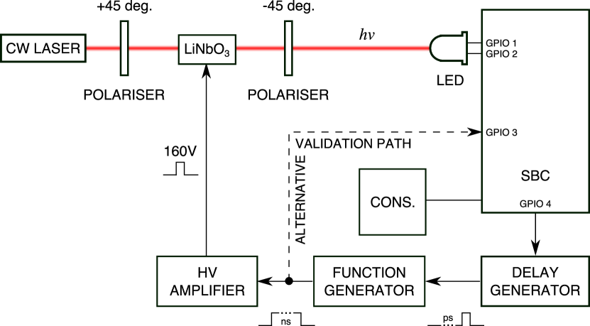
Figure 5 shows the proposed experimental setup; a visible continuous wave (CW) laser source—chosen for intensity and directivity555Also useful later on for the remote attack.—amplitude modulated by a lithium niobate crystal between two crossed polarisers and aimed at the LED under test, which is connected to two GPIO pins on the single board computer (SBC) as in the previous assumptions about target hardware.

The duty cycle of the laser illumination pulse is determined by a function generator triggered by the SBC—via any other conveniently unused GPIO pin—through a programmable delay generator. In essence, it’s a lock-in amplifier synchronised to a control signal emitted by the SBC; we use the delay generator to hunt around before and after the synchronisation pulse, looking for any vulnerable microsecond. Whilst the SBC is exercised by cycle-counted assembly language code presenting each opcode in turn exactly once in a defined time window, the delay generator will be swept across the width of the microarchitecture’s timing diagram, a coroutine watching concurrently for unexpected results in any of the CPU registers (Figure 6). Conceptually, the method is a hybrid of glitching [61] and fuzzing [62], except induced through I/O pins instead of via the power supply.
VI-C Validation Plan
The expected limitations are severe: likely it may be possible only to force a fixed value onto the internal data bus—for example, to force bits low but not high—although even that much is enough to alter a running stream of instructions; e.g., to convert a branch instruction to some other kind, thereby bypassing a security check in code.
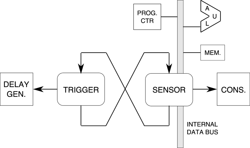
The success criteria for this experiment are dependent on the detector (Figure 7) and the injector (Figure 5). To improve the chance of success, some independent variables are eliminated. Firstly, we need only analyse one execution unit; the location of the trigger within the fetch-execute cycle can be arbitrary, because we have a delay generator. Secondly—at first—use the alternative validation path shown as a dashed line in Figure 5. By applying logic levels directly to the target pin, questions of optical intensity, aim, focus, wavelength, and LED responsivity are moot. Once the vulnerable time window has been found, then directed energy is brought back into the equation. In the worst case, this method would validate the absence of race conditions or setup/hold violations in the CPU support circuitry.
This kind of noisy, high-dimensional data analysis is exactly the kind of scientific application for which machine learning (ML) is highly applicable [49, 50, 63]. However, there are risks [64, 65]. To mitigate the scientific hazard (primarily lack of replication) of over-enthusiastic application of ML, we propose to use different methods, beginning with SciKit-Learn https://scikit-learn.org/stable/modules/outlier_detection.html for novelty and outlier detection [66]. The training phase presents a difficulty; in contrast to typical use of ML, we don’t a priori know what stimulus will result in anomalous behaviour—we have to try all stimuli. Turning the problem upside-down, therefore, we propose to train the neural network (NN) on normal behaviour—instrumented by periodic snapshotting of all registers including stack and ALU result—and then use the trained NN to detect anomalous behaviour. For the second method, TensorFlow: use a support vector machine (SVM) unsupervised to learn a soft boundary from the normal training data [67].
Funding to purchase the necessary apparatus to begin Phase II experiments is in the proposal stage. Finally, in Phase III, plan to attack the in-built LED of a standard SBC, to prove that it can be done in practice on hardware in the real world.
VII Summary and Conclusions
Possible right now is for malware to freely repurpose LED status indicators into optical receivers capable of ingesting information at least in the high range. This has been demonstrated in the lab. The chance that an attacker will find an agreeable LED available for use seems to be 70 percent, although that number depends on the hardware designer making a specific kind of mistake.
These experiments are the tip of the iceberg regarding methods for sensing—GPIO digital bipolar, GPIO digital single-ended, cathode emission, analogue GPIO (single or double-ended)—and improvements to energy transfer for Rowhammer-style attacks are all waiting to be explored.
Acknowledgements
I want to thank the anonymous reviewers for their careful reading and thoughtful suggestions. Thanks to Ireneusz Kubiak in the EMC Laboratory of Wojskowego Instytutu Ła̧czności, Zegrze, Poland; Chris Roberts in Denver, Colorado; José Lopes Esteves of ANSSI, Henry Gold of API Technologies Corp., and Ivo Kauffmann of CN Rood in the Netherlands for critical evaluation and feedback on the idea. Portions of this material were workshopped in and after an oral presentation at EMC Europe 2018 in Amsterdam [68]. The quotation in the title comes from a Daffy Duck cartoon [69].
References
- [1] F. M. Mims III, Light Emitting Diodes. Indianapolis, Indiana, USA: Howard W. Sams & Co., Inc., 1973.
- [2] F. M. Mimms, “Using LED’s as light detectors,” Popular Electronics, vol. 11, no. 5, pp. 86–88, May 1977.
- [3] F. M. Mims III, “Bidirectional optoisolator puts two LEDs nose to nose,” Electronics, vol. 52, no. 10, p. 127, 10th May 1979.
- [4] P. Dietz, W. Yerazunis, and D. Leigh, “Very low-cost sensing and communication using bidirectional LEDs,” Mitsubishi Electronics Research Laboratories (MERL), 201 Broadway, Cambridge, Massachusetts 02139, USA, Tech. Rep. TR2003-35, July 2003.
- [5] R. Stojanović and D. Karadaglić, “Single LED takes on both light-emitting and detecting duties,” Electronic Design, vol. 55, no. 16, pp. 53–54, 18th July 2007, uRL: https://www.electronicdesign.com/lighting/single-led-takes-both-light-emitting-and-detecting-duties.
- [6] F. M. Mims III, “How to use LEDs to detect light,” Make, vol. 36, p. 136, 8th January 2014.
- [7] S. Thornton, “Understanding delay for I/O: Using Arduino functions vs. coding the MCU,” EEworld Online https://www.eeworldonline.com/understanding-delay-for-i-o-using-arduino-functions-vs-coding-the-mcu/, 4 February 2019.
- [8] G. B. Stringfellow and M. G. Craford, High Brightness Light Emitting Diodes, ser. Semiconductors and Semimetals. San Diego, California: Academic Press, 1997, vol. 48.
- [9] J. Loughry and D. A. Umphress, “Information leakage from optical emanations,” ACM Transactions on Information and System Security, vol. 5, no. 3, pp. 262–289, August 2002.
- [10] B. W. Lampson, “A note on the confinement problem,” Comm. ACM, vol. 16, no. 10, pp. 613–615, October 1973.
- [11] J. Domburg, “Optical mouse cam,” http://spritesmods.com/?art=mouseeye, 2006.
- [12] M. R. Rieback, B. Crispo, and A. S. Tanenbaum, “Is your cat infected with a computer virus?” in Proceedings of the Fourth Annual IEEE International Conference on Pervasive Computing and Communications (PERCOM ’06). Washington, DC, USA: IEEE Computer Society, 2006, pp. 169–179.
- [13] B. Nassi, A. Shamir, and Y. Elovici, “Oops!…I think I scanned a malware,” arXiv:1703.07751v1 [cs.CR], 22nd March 2017.
- [14] K. Jennings, The Devouring Fungus: Tales of the Computer Age. W. W. Norton and Company, Inc., 1990.
- [15] D. E. Rosenheim, “Installation of the first production 701,” Annals of the History of Computing, vol. 5, no. 2, pp. 146–147, April–June 1983.
- [16] ON Semiconductor, “Wafer-level chip-scale package (WLCSP) at ON Semiconductor,” Fairchild Semiconductor, Application Note 5075/D, October 2018.
- [17] Micron Technology, IS32 Optic Ram data sheet, Boise, Idaho, USA, May 1984.
- [18] D. G. Whitehead, I. Mitchell, and P. V. Mellor, “A low-resolution vision sensor,” J. Phys. E: Sci. Instrum., vol. 17, pp. 653–656, 1984.
- [19] H. Kurz, “Museum für mißbrauchte bauteile,” Kurzschluss http://www.kurzschluss.com/kuckuck/kuckuck.html, 1994.
- [20] L. Upton, “Xenon death flash: a free physics lesson,” Raspberry Pi blog https://www.raspberrypi.org/blog/xenon-death-flash-a-free-physics-lesson/, 9 February 2015.
- [21] Atmel Corporation, “ATmega8 data sheet,” 2013.
- [22] Microchip Technology, Inc., “ATmega48A/PA/88A/PA/168A/PA/328/P megaAVR® data sheet,” 2018.
- [23] MediaTek, Inc., “MediaTek MT7688 datasheet,” 15th April 2016.
- [24] E. Uiga, Optoelectronics. Englewood Cliffs, New Jersey: Prentice-Hall, 1985.
- [25] W. van Eck, “Electromagnetic radiation from video display units: An eavesdropping risk?” Computer Security, vol. 4, no. 4, pp. 269–286, December 1985.
- [26] P. Wright, Spycatcher: The Candid Autobiography of a Senior Intelligence Officer. New York: Viking Press, 1987.
- [27] P. Smulders, “The threat of information theft by reception of electromagnetic radiation from RS-232 cables,” Computer Security, vol. 9, no. 1, pp. 53–58, February 1990.
- [28] P. Kocher, J. Jaffe, and B. Jun, “Differential power analysis,” in Proceedings of the 19th Annual International Cryptology Conference on Advances in Cryptology CRYPTO 99, Santa Barbara, California, 15–19 August 1999, pp. 388–397.
- [29] M. G. Kuhn, “Optical time-domain eavesdropping risks of CRT displays,” in Proceedings of the 2002 IEEE Symposium on Security and Privacy. Berkeley, California: IEEE Computer Society, 12–15 May 2002, pp. 3–18.
- [30] National Security Agency, “TEMPEST: A signal problem,” Cryptologic Spectrum, 1972.
- [31] I. Kubiak, “LED printers and safe fonts as an effective protection against the formation of unwanted emission,” Turkish Journal of Electrical Engineering and Computer Sciences, vol. 25, no. 5, pp. 4268–4279, 2017.
- [32] S. Maneki, “Learning from the enemy: the GUNMAN project,” United States Cryptologic History Series VI, vol. 13, 8th January 2007.
- [33] M. G. Kuhn and R. J. Anderson, “Soft Tempest: Hidden data transmission using electromagnetic emanations,” in Second International Workshop on Information Hiding (IH’98), Portland, Oregon, USA, 15–17 April 1998, pp. 124–142.
- [34] Advanced Network Technology (ANT) Division, “RANGEMASTER,” National Security Agency, Fort Meade, Maryland, USA, ANT Product Data, 24 July 2008.
- [35] V. Sepetnitsky, M. Guri, and Y. Elovici, “Exfiltration of information from air-gapped machines using monitor’s LED indicator,” in 2014 IEEE Joint Intelligence and Security Informatics Conference, 2014, pp. 264–7.
- [36] M. Guri, M. Monitz, Y. Mirski, and Y. Elovici, “BitWhisper: Covert signaling channel between air-gapped computers using thermal manipulations,” arXiv:1503.07919, 26th March 2015.
- [37] M. Guri, O. Hasson, G. Kedma, and Y. Elovici, “VisiSploit: An optical covert-channel to leak data through an air-gap,” https://arxiv.org/abs/1607.03946, 13 July 2016.
- [38] M. Guri, M. Monitz, and Y. Elovici, “USBee: Air-gap covert-channel via electromagnetic emission from USB,” arXiv preprint arXiv:1608.08397 [cs.CR], 30th August 2016.
- [39] M. Guri, B. Zadov, A. Daidakulov, and Y. Elovici, “xLED: Covert data exfiltration from air-gapped networks via router LEDs,” arXiv preprint 1706.01140 [cs.CR], 4th June 2017.
- [40] M. Guri, D. Bykhovsky, and Y. Elovici, “aIR-Jumper: Covert air-gap exfiltration/infiltration via security cameras & infrared (IR),” arXiv preprint arXiv:1709.05742 [cs.CR], 18th September 2017.
- [41] M. Guri, B. Zadov, A. Daidakulov, and Y. Elovici, “ODINI: Escaping sensitive data from Faraday-caged, air-gapped computers via magnetic fields,” arXiv preprint 1802.02700 [cs.CR], 8th February 2018.
- [42] M. Guri, A. Daidakulov, and Y. Elovici, “MAGNETO: Covert channel between air-gapped systems and nearby smartphones via CPU-generated magnetic fields,” Ben-Gurion University of the Negev, Cyber Security Research Center, arXiv preprint 1802.02317 [cs.CR], 7th February 2018.
- [43] M. Guri and Y. Elovici, “Bridgeware: the air-gap malware,” Comm. ACM, vol. 61, no. 4, pp. 74–82, April 2018.
- [44] M. Guri, B. Zadov, D. Bykhovsky, and Y. Elovici, “PowerHammer: Exfiltrating data from air-gapped computers through power lines,” arXiv:1804.04014 [cs.CR], 10th April 2018.
- [45] M. Guri, “BeatCoin: Leaking private keys from air-gapped cryptocurrency wallets,” arXiv preprint 1804.08714, 23 April 2018.
- [46] M. Guri, B. Zadov, A. Daidakulov, and Y. Elovici, “Covert data exfiltration from air-gapped networks via switch and router LEDs,” in 16th Annual Conference on Privacy, Security and Trust (PST), Belfast, UK, 28–30 August 2018, pp. 269–274.
- [47] M. Guri and M. Monitz, “LCD TEMPEST air-gap attack reloaded,” in 2018 IEEE International Conference on the Science of Electrical Engineering (ICSEE), Eilat, Israel, 12–14 December 2018.
- [48] M. Guri, B. Zadov, E. Arias, and Y. Elovici, “LED-it-GO: Leaking (a lot of) data from air-gapped computers via the (small) hard drive LED,” http://cyber.bgu.ac.il/advanced-cyber/system/files/LED-it-GO_0.pdf, 2017.
- [49] D. Asonov and R. Agrawal, “Keyboard acoustic emanations,” in Proceedings of the 2004 IEEE Symposium on Security and Privacy, Oakland, California, May 9–12, 2004, pp. 3–11.
- [50] L. Zhuang, F. Zhou, and J. Tygar, “Keyboard acoustic emanations revisited,” in Proceedings of the 12th ACM Conference on Computer and Communications Security, Alexandria, Virginia, November 7–11, 2005, pp. 373–382.
- [51] Y. Berger, A. Wool, and A. Yeredor, “Dictionary attacks using keyboard acoustic emanations,” in CCS’06, Alexandria, Virginia, October 30–November 3, 2006, pp. 245–254.
- [52] M. Backes, M. Dürmuth, S. Gerling, M. Pinkal, and C. Sporleder, “Acoustic side-channel attacks on printers,” in Proceedings of the 19th USENIX Security Symposium, Washington, D.C., August 11–13, 2010.
- [53] D. Genkin, M. Pattani, R. Schuster, and E. Tromer, “Synesthesia: Detecting screen content via remote acoustic side channels,” arXiv:1809.02629 [cs.CR], 7th September 2018.
- [54] I. Kubiak, “The typewriters as the sources of the sensitive acoustic signals,” in 25th International Congress on Sound and Vibration (ICSV25), Hiroshima, Japan, 8–12 July 2018.
- [55] M. Guri, Y. Solewicz, A. Daidakulov, and Y. Elovici, “Fansmitter: Acoustic data exfiltration from (speakerless) air-gapped computers,” arXiv ePrint 1606.05915, 2016.
- [56] ——, “SPEAKE(a)R: Turn speakers to microphones for fun and profit,” http://cyber.bgu.ac.il/advanced-cyber/system/files/SPEAKE(a)R.pdf, 2016.
- [57] Y. Mirsky, M. Guri, and Y. Elovici, “HVACKer: Bridging the air-gap by manipulating the environment temperature,” Magdeburger Journal zur Sicherheitsforschung, vol. 14, pp. 815–829, September 2017.
- [58] M. Guri, Y. Solwicz, A. Daidakulov, and Y. Elovici, “MOSQUITO: Covert ultrasonic transmissions between two air-gapped computers using speaker-to-speaker communication,” arXiv preprint 1803.03422v1 [cs.CR], 9th March 2018.
- [59] Y. Kim, R. Daly, J. Kim, C. Fallin, J. H. Lee, D. Lee, C. Wilkerson, K. Lai, and O. Mutlu, “Flipping bits in memory without accessing them: An experimental study of DRAM disturbance errors,” in 41st International Symposium on Computer Architecture (ISCA’14, Minneapolis, Minnesota, USA, June 14–18, 2014.
- [60] K. Shirriff, “Inside the 74181 ALU chip: die photos and reverse engineering,” http://www.righto.com/2017/01/die-photos-and-reverse-engineering.html, January 2017.
- [61] S. Skorobogatov, “Fault attacks on secure chips: from glitch to flash,” in Design and Security of Cryptographic Algorithms and Devices (ECRYPT II), Albena, Bulgaria, 29 May–3rd June 2011.
- [62] I. van Sprundel, “Fuzzing,” in 22nd Chaos Communication Congress (22C3), Berlin, Germany, 27–30 December 2005.
- [63] A. Barisani and D. Bianco, “Sniffing keystrokes with lasers/voltmeters: Side channel attacks using optical sampling of mechanical energy and power line leakage,” in CanSecWest 2009, Vancouver, British Columbia, Canada, March 16–20 2009.
- [64] G. Allen, “Machine learning and statistics: Applications in genomics and computer vision,” in AAAS Annual Meeting, Washington, DC, 15 February 2019.
- [65] P. Ghosh, “AAAS: Machine learning ‘causing science crisis’,” BBC News https://www.bbc.com/news/science-environment-47267081, 16 February 2019.
- [66] scikit-learn: Machine Learning in Python, INRIA, France, 2019.
- [67] M. Abadi, P. Barham, J. Chen, Z. Chen, A. Davis, J. Dean, M. Devin, S. Ghemawat, G. Irving, M. Isard, M. Kudlur, J. Levenberg, R. Monga, S. Moore, D. G. Murray, B. Steiner, P. Tucker, V. Vasudevan, P. Warden, M. Wicke, Y. Yu, and X. Zheng, “TensorFlow: A system for large-scale machine learning,” in Proceedings of the 12th USENIX Symposium on Operating Systems Design and Implementation (OSDI ’16), Savannah, Georgia, USA, 2–4 November 2016.
- [68] J. Loughry, “Optical TEMPEST,” in International Symposium and Exhibition on Electromagnetic Compatibility (EMC Europe 2018), Amsterdam, The Netherlands, 27–30 August 2018.
- [69] C. M. Jones, Duck Dodgers in the th Century, ser. Merrie Melodies. Warner Bros., 1953.