[1,2,3]Raghu Dharmavarapu [1]Shanti Bhattacharya [2,3,9,10]Saulius Juodkazis Raghu Dharmavarapu et.al
Dielectric cross-shaped resonator based metasurface for vortex beam generation in Mid-IR and THz wavelengths
Abstract
Metasurfaces are engineered thin surfaces comprising two dimensional (2D) arrays of sub-wavelength spaced and sub-wavelength sized resonators. Metasurfaces can locally manipulate the amplitude, phase and polarization of light with high spatial resolution. In this study, we report numerical and experimental results of a vortex-beam-generating metasurface fabricated specifically for infrared (IR) and terahertz (THz) wavelengths. The designed metasurface consisted of a 2D array of dielectric cross-shaped resonators with spatially varying length, thereby providing desired spatially varying phase shift to the incident light. The metasurface was found to be insensitive to polarization of incident light. The dimensions of the cross-resonators were calculated using rigorous finite difference time domain (FDTD) analysis. The spectral scalability via physical scaling of meta resonators was demonstrated using two vortex generating optical elements operating at 8.8m (IR) and 0.78THz (Terahertz). The vortex beam generated in the mid-IR spectral range was imaged using FTIR imaging miscroscope equipped with a focal plane array (FPA) detector. This design could be used for efficient wavefront shaping as well as various optical imaging applications in mid-IR spectral range, where polarization insensitivity is desired.
1 Introduction
Optical elements to be used in the IR and THz spectral ranges with wavelengths spanning from tens-of-m to sub-mm, and polarisation optical elements based on refraction become non-practical due to the shortage of highly transparent materials in these wavelength regimes. In addition, fabrication can often be challenging for high aspect-ratio patterns over large macroscopic areas. IR radiation and THz rays have been used and applied extensively in the optical research and development community in the past decades. While THz technology has gained an increasing demand for applications in sensing and non-invasive imaging fields[1, 2, 3], the IR-based techniques have been established as a molecular characterisation tool for a wide range of applications in microstructural analysis, spectroscopy and imaging[4, 5].
Several methods were proposed to manufacture basic optical elements for these wavelengths, such as refractive and diffractive lenses, polarizers and beam splitters[6, 7]. Recently, 3D printing was employed to manufacture non-conventional diffractive optical elements to generate complex light beams such as Bessel, Airy and vortex beams in THz and IR wavelengths[8, 9, 10]. Although 3D printing technique is often considered to be a good solution for generating custom light beams, this approach is still limited for applications that require a higher fabrication throughput due to a direct write character. There is considerably less work on THz and IR complex light generation despite their huge potential applications. Diffractive optical elements (DOEs) could be considered as a solution because they reduce the volume that should be 3D printed. However, the efficiency of DOEs is significantly lower, leading to a major limitation especially for applications in the THz spectral window.
Laguerre Gaussian beams also known as vortex beams are interesting complex beams in optics, which possess helical wavefronts and an on-axis phase singularity[11, 12]. In addition, composite vortex beams possess a self-healing property within the Rayleigh range[13]. Owing to these interesting properties, vortex beams have been used in many applications, such as optical manipulation of micro particles[14, 15], fibre optical communication[16], STED microscopy[17]. Currently, the most popular techniques to generate these beams, in the visible wavelength, include computer generated holograms[18], spatial light modulators[19], Spiral Phase Plates (SPP)[20], and so on. In 2012, P. Genevet et al. employed a V-shaped antenna-based metasurface[21] to build a vortex generating SPP in the IR spectral region. A year later, the same design concept was extended to the THz region and used to fabricate vortex generators[22] and a modified version of antenna was proposed to generate vortex beams in THz region[23]. Geometric metasurfaces, which work on the pancharatnam-Berry phase phenomenon are used to generate both scalar[24] and vector[25] vortex beams. Recently, polarization-sensitive generation and modulation[26] of OAM beams using dielectric metasurfaces based on silicon fin structures. Metasurfaces have recently become a platform to realize and apply optical spin-hall effect[27]. Metasurfaces can be built using several type of meta-atoms, such as V-shaped antennas[28], cylindrical disks[29] or nano-fin structures[30].
In this study, we develop a vortex beam generator for the mid-IR spectral range (m), using cross-shaped resonators[31], which can support both Mie-type electric and magnetic dipole resonances to realize phase manipulation and to completely suppress reflection losses. The idea behind choosing this wavelength is to use the generated vortex beam to measure the absorbance of secondary protein structures such as beta sheets in silk which also lie at in the same wavelength region[32, 33, 34, 35]. The generated vortex beam was captured, for the first time, using FTIR imaging microscope with a focal plane array (FPA) detector. To show the versatility and scalability of this design, we scaled the IR design and generated a vortex beam of charge 1 at 0.78THz. Transmission response of both s- and p-polarizations showed a polarization insensitivity for this design. Finite difference time domain (FDTD) simulation, fabrication, and optical characterisation results are presented to support the experimental results.
2 Results and discussion
2.1 Design of the unit cell
In this section, we discuss the design parameters and dimensions of silicon cross resonators to achieve high transmission and 0 to 2 phase response for full wavefront control. A schematic of the silicon cross resonator is shown in the inset of Fig.LABEL:fig:1c. Silicon was chosen due to its high relative permittivity of and its low loss nature in the THz regime. The design frequency is chosen to be 34THz, which lies in one of the absorption bands of silk in the IR spectral range. The following cross resonator dimensions are optimized to get maximum transmission and phase coverage at the chosen operational frequency. The phase coverage is achieved by changing the length of the resonator from 1.25m to 6.5m. The width, height and lattice constant of the unit cell are fixed at 1m, 1.85m and 7.25m respectively.
fig:1b
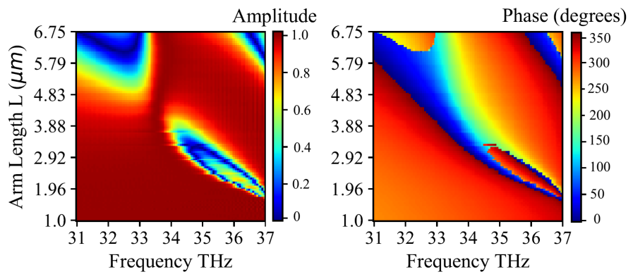
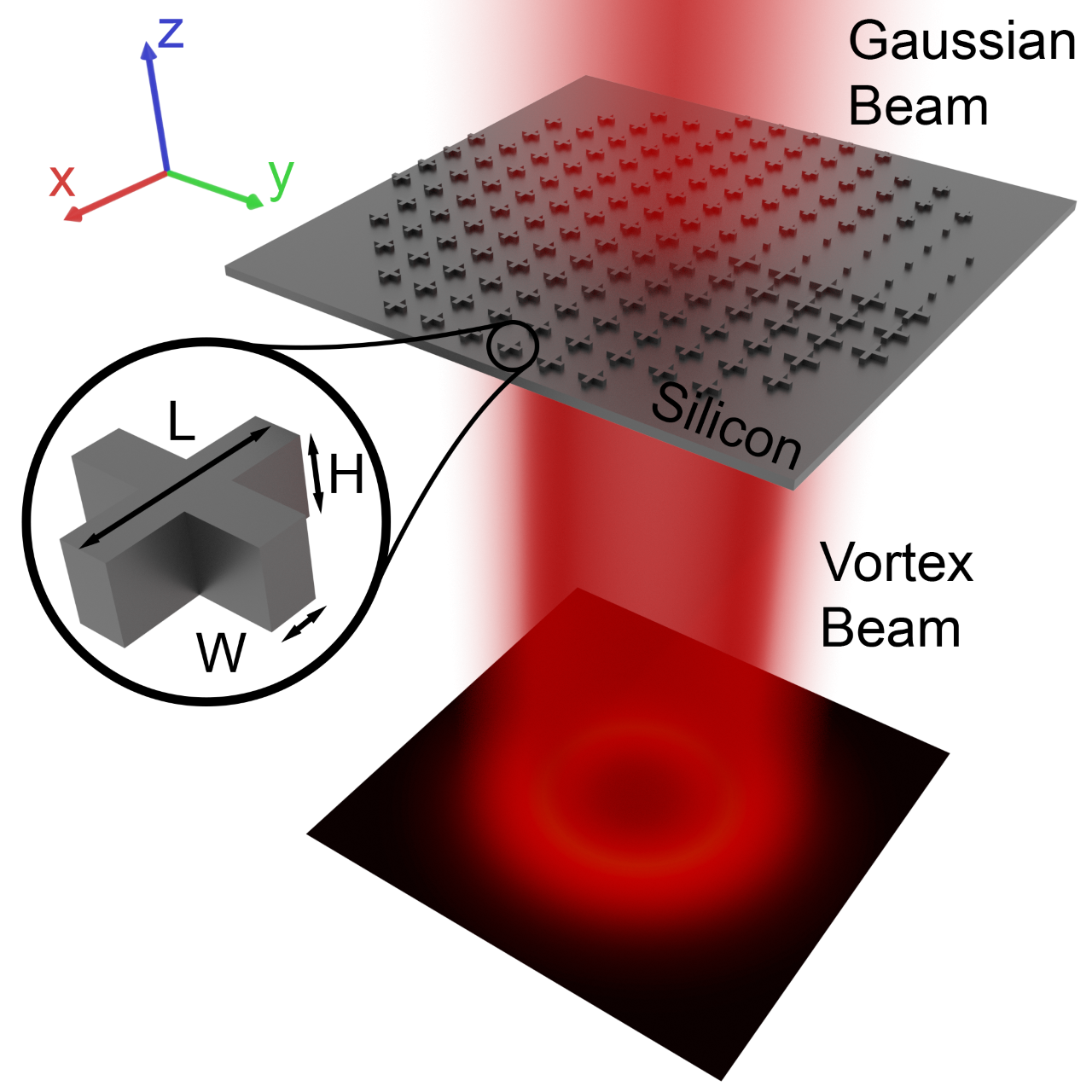
fig:1c

fig:1d
We considered the electromagnetic response of one resonator with periodic boundary condition as the spacing between the resonators is sub-wavelength, which allows very low coupling between adjacent resonators. Each resonator can support electric and magnetic resonances, when the dimensions become comparable to the wavelength of the incident light[36]. High transmission can be achieved by tuning the dimensions such that the two resonances overlap spectrally and cancel out the back scattered light. In our simulations, the refractive index model of silicon is fitted to Palik data and the incident wave is assumed to be a plane wave propagating along the axis with electric field along the direction. The transmission amplitude and phase is extracted from the S21 parameter of the FDTD simulation. The FDTD-extracted electric field amplitude and phase data, as a function of varying cross length (1.25m-6.5m) and operating frequency(31-37THz), are shown in Fig.LABEL:fig:1b. The plot in Fig.LABEL:fig:1d shows the variation of transmission amplitude and phase with respect to changing cross length from 1.25m to 6.5m, at the desired frequency 34THz ( = 8.8m).
For the THz vortex generator, we chose 0.78THz as the operating frequency. This corresponds to a wavelength of 410m. This wavelength was selected as the band close to the coherent synchrotron radiation (CSR) at 0.3-0.4THz. CSR is an unique highest brightness radiation source at the IR-beamline at the Australian synchrotron which can benefit from set of optical elements to control polarization, intensity, and wavefront. We used linear scaling approach to find the desired starting dimensions for the THz metasurface. The wavelength scaling factor is 46.5, which is calculated by taking the ratio of the two wavelengths. We found the maximum of length for the cross resonator to be approximately 300m by applying the same scaling factor to the length of the cross resonator. By using further FDTD optimization, we narrowed down the desired length range to 180m-275m to achieve 0 to 2 phase coverage at 0.78THz. The width, height and lattice constant of the cross were fixed at 70m, 150m and 380m respectively.
2.2 Mid-IR vortex generator
A metasurface for vortex beam generation at mid IR wavelengths is constructed as follows. The phase function of the vortex generator is given by a helical function as,
| (1) |
where () are the coordinates in the metasurface plane and is the topological charge of the vortex beam. The continuous phase profile of the vortex generator given in the Eq.LABEL:eq:1 is discretized to eight phase levels and eight cross dimensions with nearly equal phase steps of to cover the full range are selected from the look-up table plot Fig.LABEL:fig:1d. It can be seen that all the resonators have high transmission with a mean variation of only 5%. The schematic of the vortex generator is shown in Fig.LABEL:fig:1c.
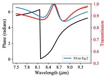
fig:tatp

fig:layout
To gain a intuitive insight into the phase tuning phenomenon of the cross resonator, a simple analytical model[37] is presented here. Each of the cross resonators can be considered as a coupled electric and magnetic dipole excited by an incident electromagnetic wave. The far-field electric field of the metasurface will be the sum of incident field and the electric and magnetic dipole radiation coming from these individual cross resonators. Therefore, the transmission coefficient of each resonator can be given by
| (2) |
where is the frequency of incident beam, and are the electric and magnetic resonance frequencies, and and are the damping factors of the electric and magnetic dipoles. Fig.LABEL:fig:tatp shows the transmission phase and amplitude simulated using FDTD(red curve) and curve fit to the analytical model given in Eq.LABEL:eq:2 for the cross resonator with an arm length of 3m. For this cross resonator, we have extracted the electric and magnetic resonance frequencies and the damping factors to be 35.0THz, 35.1THz and 2.13, 0.72 respectively using curve fitting. The difference between the analytical model and FDTD data can be attributed to the finite mesh settings of the FDTD solver. Fig.LABEL:fig:layout shows the maximum variation in transmission amplitude (T) and phase coverage () among the eight chosen cross resonators over the wavelength range (8.3-9.5m). Even though the resonators are almost providing the desired 2 (gradually decreasing) phase coverage over the entire frequency band, all the cross resonators at a specific frequency do not have the same transmission, which can be clearly seen from the dip in Fig.LABEL:fig:layout. If we consider that a variation in transmission among the resonators is acceptable, we can use this design over a bandwidth of 170nm, around 8.85m.
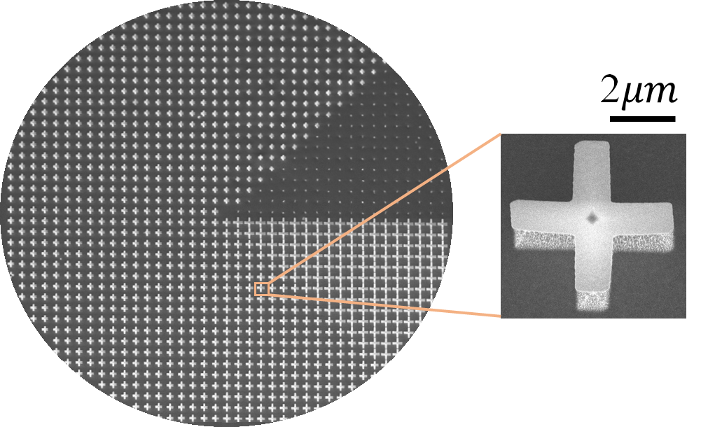
fig:9a
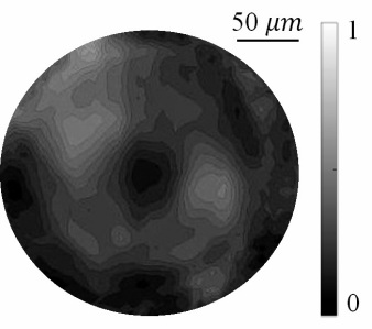
fig:9b
We used a 500m thick silicon wafer to fabricate the IR vortex generator. The device was fabricated using electron beam lithography (Vistec EBPG) followed by anisotropic dry etching using standard Bosch process, with photoresist acting as the etch mask. The etching recipe was optimized to get the desired cross height of 1.85m. A SEM image of the fabricated vortex plate is shown in Fig.LABEL:fig:9a, where the inset was captured at higher magnification to show a single cross meta-atom.
2.2.1 FPA-FTIR imaging of the vortex generator
The IR images of the vortex beam were acquired with an offline FPA-FTIR microspectroscopic instrument at the Australian Synchrotron Infrared Microspectroscopy (IRM) Beamline. The system consisted of a Bruker Hyperion 3000 FTIR microscope (Bruker Optik GmbH, Ettlingen, Germany), equipped with a liquid-N2 cooled element FPA detector and a matching objective and condenser (NA = 0.40), which was coupled to a Vertex 70 FTIR spectrometer (Bruker Optik GmbH, Ettlingen, Germany) containing an internal thermal (GlobarTM) IR source.
FPA-FTIR images were collected in transmission mode within a 4000 to 800 cm spectral region as a single FTIR image covering a sampling area of m2. Each FTIR spectral image consisted of a array of spectra, resulting from each square of the detector on the element FPA array. As a consequence, a single spectrum contained in a FTIR image represented approximately m2 area on the sample plane.
For each image, high-quality FTIR spectral images were collected at 4 cm-1 resolution, with 128 co-added scans, Blackman-Harris 3-Term apodization, Power-Spectrum phase correction, and a zero-filling factor of 2 using OPUS 7.2 imaging software (Bruker). Background measurements were taken using the same acquisition parameters prior to sample spectral images, by focusing on a clean surface area of the substrate without the vortex pattern. All spectra were analyzed using OPUS v7.2 software, by integrating the area under the narrow spectral range around 1136cm-1(m). FigureLABEL:fig:9b shows the vortex beam captured on the FPA detector. The low image quality can be attributed to the usage of only 8 steps in the SPP and lower resolution of the FPA sensor itself. A higher number of phase steps would improve the contrast of vortex intensity profile.
2.3 THz vortex generator
We designed a SPP with a diameter 1.2cm consisting of eight phase levels in its eight octants. Each of the octant contains an array of cross resonators such that the phase varies from 0 to 2 azimuthally across vortex generator. Such an optical element has dimensions useful for a range of applications in THz experiments. The FDTD simulation of the transmitted phase and electric field amplitude are shown in Fig.LABEL:fig:4a and LABEL:fig:4b respectively. The designed spiral phase was found to indeed follow the required azimuthal span. We experimentally show the high transmission and polarization independence for this metasurface. However, we could not image the vortex generator in a raster scan mode as our experimental setup is not capable of such mapping.
To simulate the SPP and the doughnut intensity pattern of the vortex generator, we created its GDSII layout(Schematic shown in Fig.LABEL:fig:1c) using in-house developed software MetaOptics[38]. MetaOptics uses FDTD transmission phase vs varying dimension data of a meta-atom and creates GDSII layouts of any phase distribution by placing a meta-atom that gives the desired transmission phase at that pixel of the phase mask. The generated GDSII file is loaded in the Lumerical FDTD solver for simulation. The corresponding simulated phase and doughnut intensity pattern are shown in Fig.LABEL:fig:4a and LABEL:fig:4b.
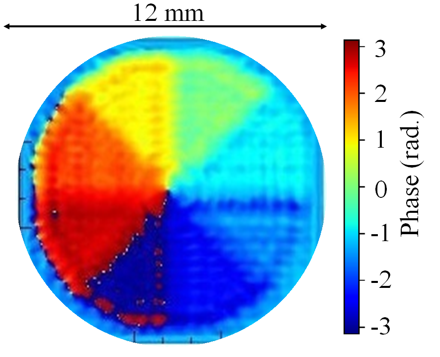
fig:4a
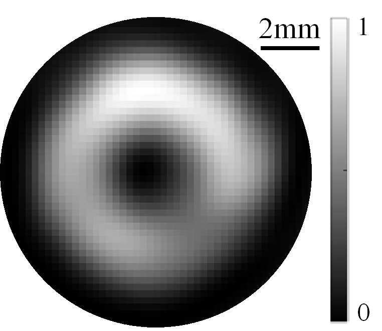
fig:4b
fig:5a
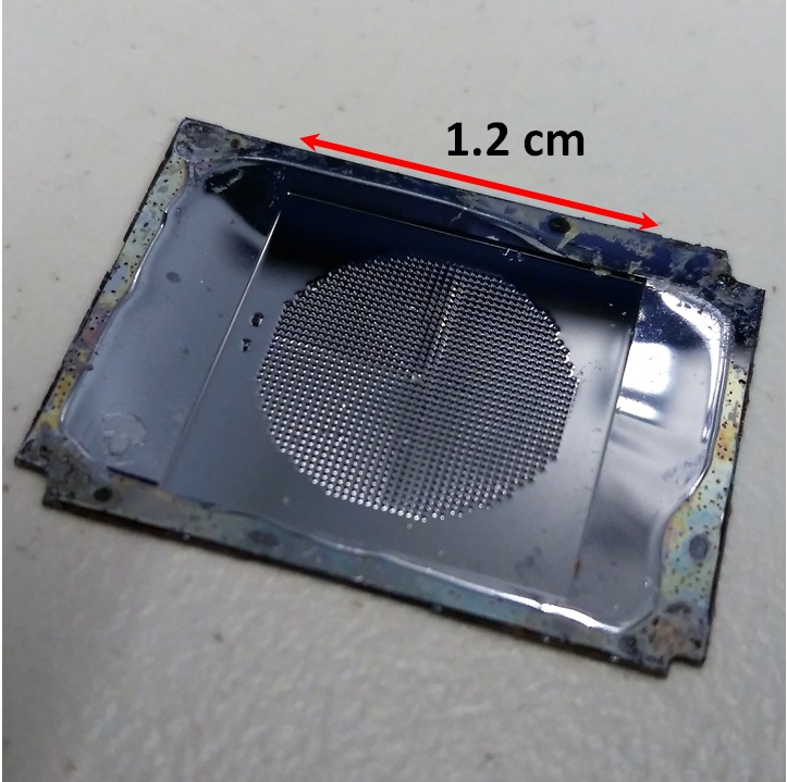
fig:5b
2.3.1 Fabrication of vortex generator
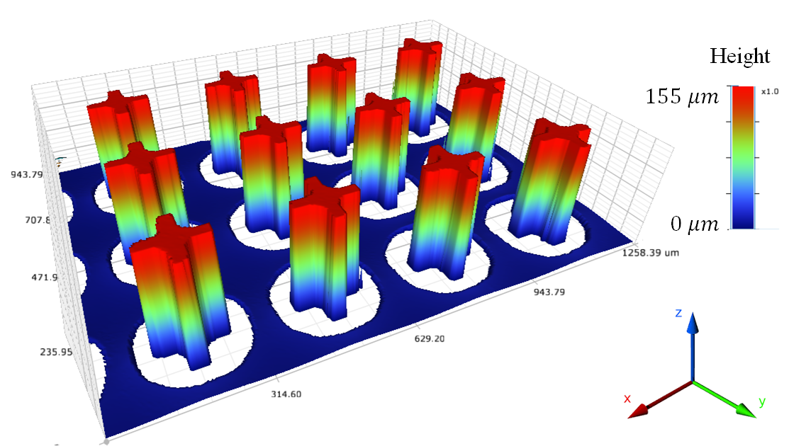
A 300m thick intrinsic silicon wafer was used for the fabrication of the optical meta-surface element. The device was fabricated using photolithography followed by reactive ion etching (RIE). The mask for the photolithography was fabricated using the Intelligent micropatterning SF100 XPRESS direct writing system. To achieve a m thick resist layer, AZ4562 photoresist was spin coated at 2000rpm. The large thickness was needed to obtain a high etch depth of 150m by RIE (as the resist acts as a sacrificial mask during this process). The resist was exposed at a dose of 485J/cm2, then developed in AZ726 MIF for 5minutes. The standard Bosch process was used to etch silicon for the required high aspect ratio pattern. A photograph of the fabricated metadevice and an optical profilometer measurement are shown in Fig.LABEL:fig:5a and LABEL:fig:5b. The required depth of 150m was achieved after 90mins of plasma etching.
2.3.2 Characterization by time domain spectroscopy
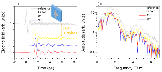
The THz time domain spectroscopy (THz-TDS) was applied to characterise performance of the THz vortex generator shown in Fig.LABEL:fig:5a.Terahertz transmission spectra of the microstructures were measured using a home-made terahertz time-domain spectrometer (THz-TDS) using a 10-fs Ti:sapphire oscillator with the repetition rate of 80MHz and output power of 300mW. The terahertz waves are generated and detected by low-temperature grown GaAs photoconducting antennae used in a reflection geometry[39]. The terahertz spectrum spans throughout a broad bandwidth from 0.2 to 15THz with a dip at 8THz. The transmittance of the samples are characterized by the ratio of the spectrum of transmitted terahertz wave through the sample with that through the bare silicon substrate with the same thickness. We measured the transmittance at several different positions on the vortex generators. The positions of the incident terahertz waves were confirmed by the residual of the pump laser reflected from the surface of the generation photoconducting antenna. This guide light was filtered by an additional silicon plate during the measurement. The system was purged with nitrogen to avoid water vapor absorption.
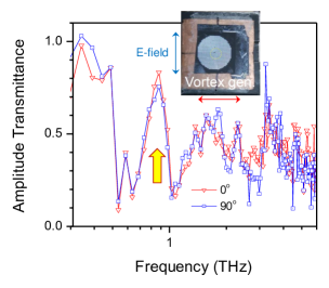
Almost identical E-field transients were observed in transmission at the two perpendicular polarisations as shown by the waveform and its Fourier transform (spectrum) in Fig.LABEL:f-K1. Transmission performance of vortex generators designed for maximum at 0.78THz are shown in Fig.LABEL:f-K2. Closely matched spectral performance for two perpendicular polarisations was observed with transmittance maximum at a slightly shifted 0.8THz wavelength. The deviation is due to the slight mismatch between the simulated and fabricated dimensions of the cross resonator.
The pattern of cross-antennas is also performing as a spectral filter. A promising application is to combine filter and focusing by flat Fresnel lens pattern to increase signal-to-noise ratio in optical filtering as was recently demonstrated by laser ablation[40].
3 Conclusions
Metasurfaces composed of azimutally rotated sections of cross-antennas patterned at different cross lengths and fixed period , were used to fabricate optical vortex generators. By using Si, it is demonstrated that high transmission optical elements at the designed wavelength in mid-IR and THz spectral ranges can be made. High refractive index of Si is beneficial for the required overlap of electric and magnetic resonances for the cross-antennas used in this work. The used cross-antenna design is beneficial for polarization insensitive performance of the vortex beam generators. This is a useful virtue for synchrotron applications where the beam has a complex polarization composition[41].
This study shows that a missing toolbox of optical elements imparting Orbital Angular Momentum (OAM) onto beams at IR spectral ranges is readily available using a metasurface approach. We used a linear scaling approach to demonstrate the vortex generator at THz wavelength and experimentally demonstrate a high transmission and polarization independent behaviour. Simulation results show desired spatial phase variability needed for beam shaping applications.
Acknowledgements
The FPA-FTIR imaging experiment was undertaken on the offline FTIR instrument at the Australian Synchrotron IRM Beamline, part of ANSTO, during the approved beamtime for Proposal ID. M13416. This work was performed in part at the Melbourne Centre for Nanofabrication (MCN) in the Victorian Node of the Australian National Fabrication Facility (ANFF). This research was partially funded by JSPS KAKENHI. A.K. is grateful for support via the Russian Science Foundation grant no. 18-79-10091, R.D. thanks IIT Madras–Swinburne joint PhD program.
References
- [1] C.Jansen, S.Wietzke, O.Peters, M.Scheller, N.Vieweg, M.Salhi, N.Krumbholz, C.Jördens, T.Hochrein, M.Koch, Terahertz imaging: applications and perspectives, Appl. Opt. 49(19) (2010) E48–E57.
- [2] A.Redo-Sanchez, X.-C. Zhang, Terahertz science and technology trends, IEEE J Sel. Topics Quantum Electr. 14(2) (2008) 260–269.
- [3] A.Bitzer, M.Walther, Terahertz near-field imaging of metallic subwavelength holes and hole arrays, Appl. Phys. Lett. 92(23) (2008) 231101.
- [4] R.Honda, M.Ryu, A.Balčytis, J.Vongsvivut, M.J. Tobin, S.Juodkazis, J.Morikawa, Paracetamol micro-structure analysis by optical mapping, Applied Surface Science 473 (2019) 127–132.
- [5] R.Honda, M.Ryu, J.-L. Li, V.Mizeikis, S.Juodkazis, J.Morikawa, Simple multi-wavelength imaging of birefringence: case study of silk, Sci. Rep. 8(1) (2018) 17652.
- [6] M.Tonouchi, Cutting-edge terahertz technology, Nature Photonics 1(2) (2007) 97.
- [7] D.Mittleman, Sensing with terahertz radiation, Vol.85, Springer, 2013.
- [8] X.Wei, C.Liu, L.Niu, Z.Zhang, K.Wang, Z.Yang, J.Liu, Generation of arbitrary order bessel beams via 3d printed axicons at the terahertz frequency range, Appl. Opt. 54(36) (2015) 10641–10649.
- [9] C.Liu, L.Niu, K.Wang, J.Liu, 3d-printed diffractive elements induced accelerating terahertz airy beam, Optics express 24(25) (2016) 29342–29348.
- [10] F.Machado, P.Zagrajek, V.Ferrando, J.A. Monsoriu, W.D. Furlan, Multiplexing thz vortex beams with a single diffractive 3-d printed lens, IEEE Trans. Terahertz Sci. Technol. 9(1) (2019) 63–66.
- [11] J.F. Nye, M.V. Berry, Dislocations in wave trains, Proc. Royal Soc. London. A. Math. Phys. Sci. 336(1605) (1974) 165–190.
- [12] S.M. Barnett, L.Allen, Orbital angular momentum and nonparaxial light beams, Opt. Comm. 110(5-6) (1994) 670–678.
- [13] P.Srinivas, C.Perumangatt, N.Lal, R.Singh, B.Srinivasan, Investigation of propagation dynamics of truncated vector vortex beams, Opt. Lett. 43(11) (2018) 2579–2582.
- [14] H.He, M.Friese, N.Heckenberg, H.Rubinsztein-Dunlop, Direct observation of transfer of angular momentum to absorptive particles from a laser beam with a phase singularity, Phys. Rev. Lett. 75(5) (1995) 826.
- [15] J.Ng, Z.Lin, C.Chan, Theory of optical trapping by an optical vortex beam, Phys. Rev. Lett. 104(10) (2010) 103601.
- [16] A.E. Willner, H.Huang, Y.Yan, Y.Ren, N.Ahmed, G.Xie, C.Bao, L.Li, Y.Cao, Z.Zhao, etal., Optical communications using orbital angular momentum beams, Adv. Opt. Photon. 7(1) (2015) 66–106.
- [17] K.I. Willig, S.O. Rizzoli, V.Westphal, R.Jahn, S.W. Hell, Sted microscopy reveals that synaptotagmin remains clustered after synaptic vesicle exocytosis, Nature 440(7086) (2006) 935.
- [18] N.Heckenberg, R.McDuff, C.Smith, A.White, Generation of optical phase singularities by computer-generated holograms, Opt. Lett. 17(3) (1992) 221–223.
- [19] N.Matsumoto, T.Ando, T.Inoue, Y.Ohtake, N.Fukuchi, T.Hara, Generation of high-quality higher-order laguerre-gaussian beams using liquid-crystal-on-silicon spatial light modulators, J. Opt. Soc. Am. A 25(7) (2008) 1642–1651.
- [20] M.Beijersbergen, R.Coerwinkel, M.Kristensen, J.Woerdman, Helical-wavefront laser beams produced with a spiral phaseplate, Opt. Comm. 112(5-6) (1994) 321–327.
- [21] P.Genevet, N.Yu, F.Aieta, J.Lin, M.A. Kats, R.Blanchard, M.O. Scully, Z.Gaburro, F.Capasso, Ultra-thin plasmonic optical vortex plate based on phase discontinuities, Appl. Phys. Lett. 100(1) (2012) 013101.
- [22] D.Hu, X.Wang, S.Feng, J.Ye, W.Sun, Q.Kan, P.J. Klar, Y.Zhang, Ultrathin terahertz planar elements, Adv. Opt. Mat. 1(2) (2013) 186–191.
- [23] J.He, X.Wang, D.Hu, J.Ye, S.Feng, Q.Kan, Y.Zhang, Generation and evolution of the terahertz vortex beam, Opt. Express 21(17) (2013) 20230–20239.
- [24] R.C. Devlin, A.Ambrosio, N.A. Rubin, J.B. Mueller, F.Capasso, Arbitrary spin-to–orbital angular momentum conversion of light, Science 358(6365) (2017) 896–901.
- [25] F.Yue, D.Wen, J.Xin, B.D. Gerardot, J.Li, X.Chen, Vector vortex beam generation with a single plasmonic metasurface, ACS photonics 3(9) (2016) 1558–1563.
- [26] C.Yan, X.Li, M.Pu, X.Ma, F.Zhang, P.Gao, Y.Guo, K.Liu, Z.Zhang, X.Luo, Generation of polarization-sensitive modulated optical vortices with all-dielectric metasurfaces, ACS Photonics.
- [27] S.Xiao, J.Wang, F.Liu, S.Zhang, X.Yin, J.Li, Spin-dependent optics with metasurfaces, Nanophotonics 6(1) (2016) 215–234.
- [28] A.V. Kildishev, A.Boltasseva, V.M. Shalaev, Planar photonics with metasurfaces, Science 339(6125) (2013) 1232009.
- [29] K.E. Chong, I.Staude, A.James, J.Dominguez, S.Liu, S.Campione, G.S. Subramania, T.S. Luk, M.Decker, D.N. Neshev, etal., Polarization-independent silicon metadevices for efficient optical wavefront control, Nano Lett. 15(8) (2015) 5369–5374.
- [30] M.Khorasaninejad, W.T. Chen, R.C. Devlin, J.Oh, A.Y. Zhu, F.Capasso, Metalenses at visible wavelengths: Diffraction-limited focusing and subwavelength resolution imaging, Science 352(6290) (2016) 1190–1194.
- [31] R.Dharmavarapu, S.H. Ng, S.Bhattacharya, S.Juodkazis, All-dielectric metasurface for wavefront control at terahertz frequencies, in: Nanophotonics Australasia 2017, Vol. 10456, International Society for Optics and Photonics, 2018, p. 104561W.
- [32] A.Balčytis, M.Ryu, X.Wang, F.Novelli, G.Seniutinas, S.Du, X.Wang, J.Li, J.Davis, D.Appadoo, J.Morikawa, S.Juodkazis, Silk: Optical properties over 12.6 octaves THz-IR-Visible-UV range, Materials 10(4) (2017) 356.
- [33] M.Ryu, H.Kobayashi, A.Balčytis, X.Wang, J.Vongsvivut, J.Li, N.Urayama, V.Mizeikis, M.Tobin, S.Juodkazis, J.Morikawa, Nanoscale chemical mapping of laser-solubilized silk, Mat. Res. Express 4(11) (2017) 115028.
- [34] M.Ryu, A.Balčytis, X.Wang, J.Vongsvivut, Y.Hikima, J.Li, M.J. Tobin, S.Juodkazis, J.Morikawa, Orientational mapping augmented sub-wavelength hyper-spectral imaging of silk, Sci. Reports 7 (2017) 7419.
- [35] M.Ryu, R.Honda, A.Cernescu, A.Vailionis, A.Balcytis, J.Vongsvivut, J.-L. Li, D.Linklater, E.Ivanova, V.Mizeikis, M.Tobin, J.Morikawa, S.Juodkazis, Nanoscale optical and structural characterisation of silk, Beilstein J. Nanotechnol. 10 (2019) 922–929.
- [36] A.B. Evlyukhin, C.Reinhardt, A.Seidel, B.S. Luk’yanchuk, B.N. Chichkov, Optical response features of si-nanoparticle arrays, Phys. Rev. B 82(4) (2010) 045404.
- [37] M.Decker, I.Staude, M.Falkner, J.Dominguez, D.N. Neshev, I.Brener, T.Pertsch, Y.S. Kivshar, High-efficiency dielectric huygens’ surfaces, Adv. Opt. Mat. 3(6) (2015) 813–820.
- [38] R.Dharmavarapu, S.Bhattacharya, S.Juodkazis, MetaOptics: Software for creating GDSII layouts of metasurface phase masks, http://www.ee.iitm.ac.in/AppliedOptics/MetaOptics.exe, [Online; accessed 01-April-2019] (2019).
- [39] K.Yokota, J.Takeda, C.Dang, G.Han, D.N. McCarthy, T.Nagao, S.Hishita, M.Kitajima, I.Katayama, Surface metallic states in ultrathin Bi(001) films studied with terahertz time-domain spectroscopy, Appl. Phys. Lett. 100 (2012) 251605.
- [40] M.Tamošiūnaitė, S.Indrišiūnas, V.Tamošiūnas, L.Minkevičius, A.Urbanowicz, G.Račiukaitis, I.Kašalynas, G.Valušis, Focusing of terahertz radiation with laser-ablated antireflective structures, IEEE Trans. Terahertz Sci. Technol. 8(5) (2018) 541–548.
- [41] M.Ryu, D.Linklater, W.Hart, A.Balčytis, E.Skliutas, M.Malinauskas, D.Appadoo, Y.Tan, E.P. Ivanova, J.Morikawa, S.Juodkazis, 3D printed polarising grids for IR-THz synchrotron radiation, J. Opt. 20 (2018) 035101.
lastpage