Graded index lenses for spin wave steering
Abstract
We use micromagnetic modelling to demonstrate the operation of graded index lenses designed to steer forward-volume magnetostatic spin waves by 90 and 180 degrees. The graded index profiles require the refractive index to diverge in the lens center, which, for spin waves, can be achieved by modulating the saturation magnetization or external magnetic field in a ferromagnetic film by a small amount. We also show how the 90∘ lens may be used as a beam divider. Finally, we analyse the robustness of the lenses to deviations from their ideal profiles.
I Introduction
Future wave-based computers will need to carry out certain functions to control propagating waves. One important function is to steer a wave beam or a wave packet in a controlled manner. For spin waves in ferromagnets Stancil and Prabhakar (2009); Kruglyak et al. (2010); Lenk et al. (2011); Chumak et al. (2015), a possible contender for wave-based computing, this has mostly been investigated in terms of confining waves along curved waveguides Vogt et al. (2012); Xing et al. (2013, 2015); Garcia-Sanchez et al. (2015); Lan et al. (2015); Sadovnikov et al. (2017). However, these waveguides may suffer from losses/scattering in bends, and usually have a large spatial footprint. An alternative solution is to steer spin waves via a graded refractive index Davies and Kruglyak (2015); Dzyapko et al. (2016); Gruszecki and Krawczyk (2018); Vogel et al. (2018), which smoothly alters the wave trajectory with minimal reflections Whitehead et al. (2018). To achieve a graded index for spin waves, one must gradually change a magnonic parameter on a length scale much smaller than the wavelength.
In optics, wave steering via a graded index is a well-established technique. One spatially-efficient method of steering is via rotationally-symmetric profiles (lenses), which are specifically designed to steer light by a certain angle between 0∘ and 360∘, and can do so from any direction of incidence Eaton (1952); Cornbleet and Rinous (1981); Miñano (2006); Schmiele et al. (2010); Chang et al. (2012); Šarbort and Tyc (2012). Although these lenses are designed to work with light, the same analysis applies to any other wave, supposing that the dispersion relation is known.
A practical problem with these lenses is that they require a singular refractive index in the center, while even a moderately large refractive index is difficult to achieve in most areas of wave physics, One technique to avoid this problem is via transformation optics Tyc and Leonhardt (2008); Hooper and Philbin (2013); Horsley et al. (2014). The profile can also be truncated, but this often results in an incorrect trajectory Zentgraf et al. (2011).
Here, we show that an extremely high refractive index can quite easily be achieved for magnetostatic (dipolar) spin waves in the forward-volume geometry. Although a singular index is obviously still impossible, the refractive index can become high enough to closely match the required refractive index profile of these steering lenses. We use micromagnetic modelling to demonstrate how two of these lenses can be realized for spin waves in the dipolar regime, and analyse the lenses’ robustness to profile deviations.
II Theory of Spin Wave Steering Lenses
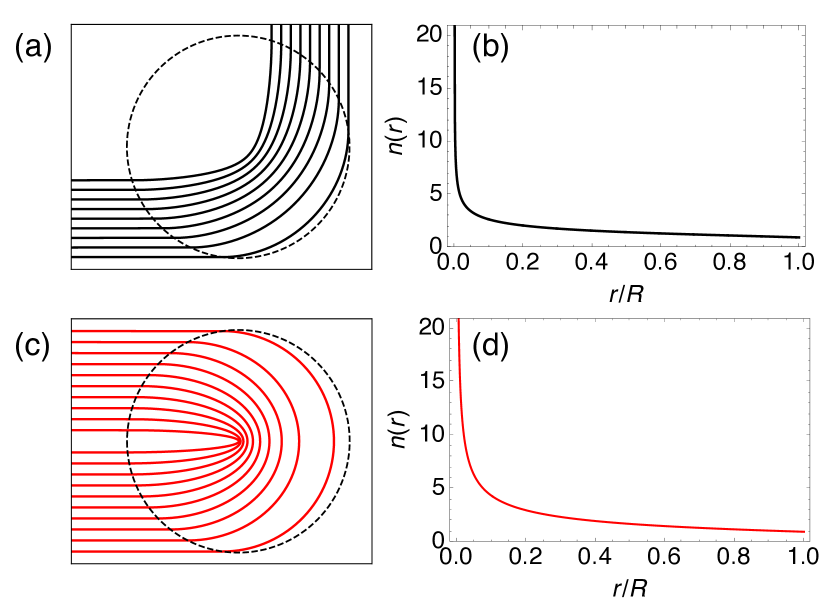
We first explain the properties of the steering lenses, and then show how they may be implemented for spin waves. We will be using the 90∘ lens Cornbleet and Rinous (1981); Schmiele et al. (2010) and Eaton (180∘) lens Eaton (1952). Fig. 1 compares their respective refractive index profiles, defined as Šarbort and Tyc (2012)
| (1) |
| (2) |
where is the radial coordinate and is the radius of the lens in each case. Note that the profile for the 90∘ lens (1) is defined implicitly here.
Defining a refractive index profile for spin waves is non-trivial, since the dispersion relation is strongly dependent on the geometry, and is always nonlinear. In some geometries it is also highly anisotropic. The simplest way to implement the rotationally-symmetric profiles is via a geometry with an isotropic dispersion relation, and design each lens for a fixed incident wave frequency, although it should work also for a wave packet with a small frequency spread. The refractive index is defined as the ratio of the wave number inside the lens, , to that outside the lens, ,
| (3) |
To change the wave number and thus the index for the given wave frequency, we need to change the dispersion relation by varying one of the bulk material parameters, or film thickness Davies and Kruglyak (2015); Dzyapko et al. (2016); Gruszecki and Krawczyk (2018); Vogel et al. (2018); Whitehead et al. (2018).
We then need to choose an isotropic dispersion relation that enables a large change in , and thus . This requirement is satisfied in the dipolar-dominated regime, in the forward-volume geometry, where the magnetization is directed normal to the film plane. The dipole-dipole interaction dominates the dispersion for spin wave wavelengths of millimeters to micrometers. At the other end of the spectrum, the short-range exchange interaction dominates, for wavelengths from tens to hundreds of nanometers. In the crossover regime, the dispersion curve flattens out before the exchange interaction begins to have a stronger influence. It is this shallow gradient in the crossover regime that enables a large index to be obtained. The forward-volume dipole-exchange dispersion relation can be written for the angular frequency as Kalinikos and Slavin (1986)
| (4) |
where , , and . Here, is the permeability of free space, is the gyromagnetic ratio, is the applied external magnetic field, is the saturation magnetization, is the film thickness and is the exchange length, where J/m is the exchange constant. In this paper, we will use the following values outside of the lens for the magnetization, magnetic field and film thickness, respectively: kA/m, mT, and m. The resulting value of exchange length is nm. These values determine , and thus the index will be 1 when , and .
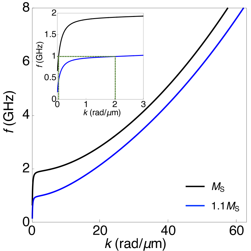
Using the material parameters listed above, the dipole-exchange dispersion relation is plotted in Fig. 2, where we also show the effect of increasing by 10%. This small change in leads to a large change in , and thus , due to the shallow gradient in the crossover region between the dipolar-dominated and exchange-dominated regimes. The corresponding change in the index is from 1 to 54 for a fixed frequency of 1 GHz. The use of a thick film of 10m enables a particularly large index to be achieved, because the shallow gradient extends to larger values. In comparison, a thinner film of 2 m leads to an index change from 1 to 28 for the same 10% increase in . Note that the value of at marks the lower threshold of the spin wave ‘manifold’, which corresponds to the ferromagnetic resonance frequency. In Eq. (4), this occurs when and thus .
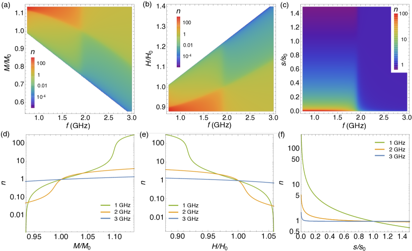
In Fig. 3, we show how the index depends on the three parameters that can be varied in Eq. (4) (, and ), for different incident wave frequencies . In Fig. 3 (a)-(c), we can see the distinct dipole-dominated and exchange-dominated regimes, for GHz and GHz, respectively. The transition region between these two regimes is where the dispersion curve flattens at around 1.9 GHz, as we saw in Fig. 2. The white regions in panels (a) and (b) correspond to values of or for which there are no spin wave solutions for the given value of frequency, i.e. when the bottom of the spin wave manifold is above the chosen value of frequency. We have limited in (a) and (d) and in (b) and (e) to ensure that , i.e. to keep the internal magnetic field positive and thus avoid any instability. In addition, we have chosen the smallest value of to correspond to a maximum wavelength of 1mm when the index is equal to 1.
Notice from Fig. 3 that an increase in the magnetization or a decrease in the magnetic field / thickness is required to increase the index. For the former case, this may be achieved via cooling (as heating naturally reduces the magnetization Vogel et al. (2015)) or doping Fassbender and McCord (2006). Although we show the variation of the index with thickness according to (4), a graded index profile created in this way may induce complicated static or dynamic demagnetizing fields Dove (1967); Schlömann and Joseph (1970); Langer et al. (2017), not accounted for here. However, these effects may be reduced by slowly changing the thickness over a large distance.
Strikingly, Fig. 3 shows that just a relatively small change in or is required to produce a dramatic change in the index in the dipolar regime. This regime is therefore ideal to create the extreme refractive index profiles required for the steering lenses. In addition, refractive index profiles that require only a small change in the index, such as the Luneburg lens, may be created in this geometry by a tiny change in the same parameters Whitehead et al. (2018). Exchange-dominated spin waves require a large change in one of the parameters for a comparatively modest change in , as we show for the 3 GHz wave frequencies in Fig. 3.
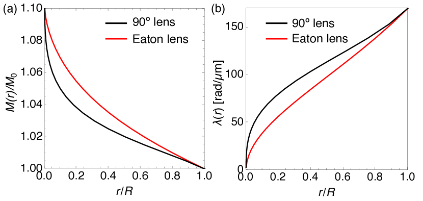
Changing the saturation magnetization is more straightforward in micromagnetic modelling, so we will vary in this work to vary the index. Using the steering lens profiles (1)-(2), along with the dipole-exchange dispersion relation (4), we can establish numerically the magnetization profile to create each lens. For the choice of material / incident wave parameters listed below, we show the required magnetization profiles in Fig. 4 (a), and the corresponding wavelength profiles in (b). For clarity, we show the profiles up to , which corresponds to a value of of and for the 90∘ and Eaton lenses, respectively. So, the majority of the profile is shown except for the singular index region in the very center.
III Micromagnetic Modelling
In order to verify the above analysis, we have performed micromagnetic simulations using MuMax3 software Vansteenkiste et al. (2014). We model an yittrium iron garnet (YIG) film with thickness m in the direction, and extent of around 6mm6mm in the plane. The axes are defined in Fig. 5. As before, the saturation magnetization outside each lens is set to kA/m and the bias magnetic field is mT in the direction. We set the Gilbert damping parameter to .
We use a cell size of m with cells in the directions. This choice of cell size is a compromise between resolving the smallest possible wavelength, and being able to represent a large enough lens. From Fig. 4 (b), we can see that if we direct the incident waves to avoid the region , then the smallest wavelength should easily be greater than 15m, which is 10 times larger than the cell size in the film plane. This approach is a necessity for the modelling, but should not be a limitation for any future experiments. If the profile in Fig. 4 can be created, this should represent the refractive index profile almost exactly.
We now describe the form of the incident wave. The lenses are primarily designed to steer a collimated beam, and we create this with a magnetic field of the form in time, where and is the excitation frequency. Spatially, this magnetic field is Gaussian in and has a step profile in , 8 cells wide, similar to the approach in Ref. Gruszecki et al., 2014. The magnetic field is directed along , with an amplitude of 0.2 mT, and a frequency of GHz. We also find that the lenses work well with a wave packet, which we position to be partly steered by the lens and partly unaffected by it, similar to the approach in Ref. Ma et al., 2009. We create the wave packet by amending the beam’s magnetic field profile to be of the form , where is a Gaussian in , or , , and m is the spin wave wavelength outside of the lens for excitation frequency . We also employ absorbing boundary layers along the edges in the and directions Venkat et al. (2018).
A perfectly graded index is not possible in finite difference simulations, but a stepped profile can work effectively if the steps are much smaller than the wavelength. This also holds true in experiments, as per the metamaterial approach Vasić et al. (2010). In the model, we allocate 233 concentric circular regions to the lens, where the radius of each region is sized to ensure that steps up by equal amounts each time, until reaching as per Fig. 4. However, this profile will not be matched exactly due to the cell size, especially where is required to change substantially on a length scale which is smaller than the cell size. This is only an issue towards the center of the lens and may lead to some scattering, which should be mitigated somewhat by avoiding the central region of .
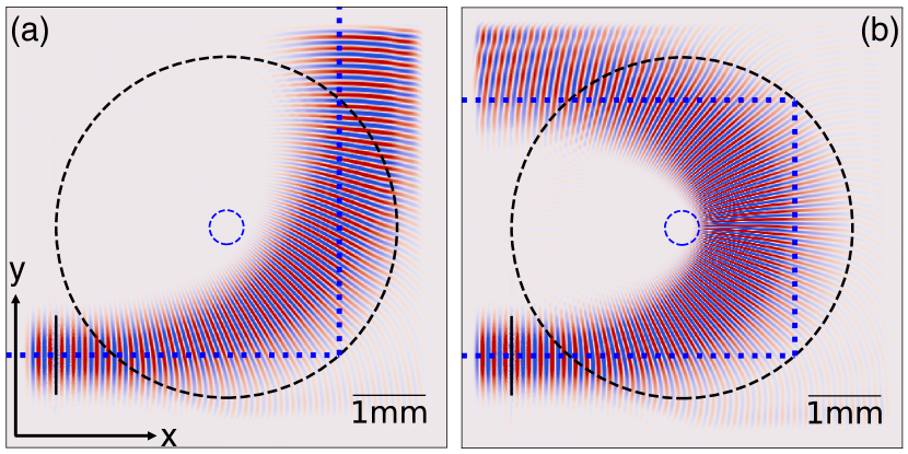
In Fig. 5, we show the beam’s trajectory through each lens, after a long enough time has elapsed. Both lenses are sized at , to ensure the beam is mostly contained within the lens. We can see that the 90∘ lens works particularly well to bend the beam by the required angle, although there is some expected spreading of the beam within and on exiting the lens, making it difficult to see if the trajectory follows the required angle exactly. The Eaton lens is quite sensitive to the placement of the beam, as the beam tends to spread into the central region, where the cell size limits how well we can represent the refractive index profile. We have found that positioning the beam towards the edge of the lens means the central region is mostly avoided, and the trajectory is around 175∘. Note for both images that the absorbing boundaries have absorbed the edge of the outgoing beam, so the actual outgoing beam is a little wider than shown.
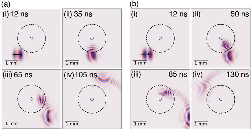
We show the results for the wave packet incident on the 90∘ and Eaton lenses in Fig. 6, and the corresponding videos are provided in the Supplemental Material 111See Supplemental Material for videos of the results shown in Fig. 6. We can see that in each case, the portion of the wave packet that enters the lens is steered approximately by the required angle, and remains ‘connected’ to the other portion of the packet that does not enter the lens and hence continues on the original trajectory. Interestingly, this implies that the part of the wave joining these two portions of the wave packet experiences an effective graded index, despite being in a homogeneous medium; its wavefronts must be curved, to bridge the two diverging parts of the wave packet Philbin (2014). The use of the lenses in this way is similar to a beam divider, and may be a way to send different portions of the same wave (beam or packet) to more than one output, albeit with some loss en route.
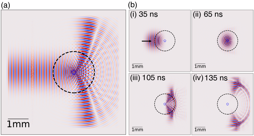
In Fig. 7, we show another use for the 90∘ lens when the beam is instead positioned to enter the lens symmetrically about the center. In this case, the lens acts as a half-power beam divider, proposed by Ref. Cornbleet and Rinous, 1981. This works well for both a beam (Fig. 7 (a)) and wave packet (Fig. 7 (b)), albeit with some scattering from the central region. Note that we have broadened the excitation width across the direction, to ensure that the beam is exposed to as much of the lens as possible, without having to reduce the lens size. In addition, we have reduced the excitation amplitude to 1 mT in both cases, to avoid a nonlinear response when the wave encounters the high-index central region. The corresponding videos are provided in the Supplemental Material 222See Supplemental Material for videos of the results shown in Fig. 7.
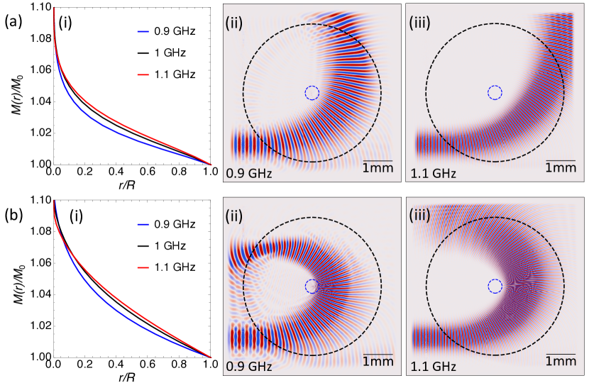
So far, we have seen the results for each lens when the refractive index profile is designed correctly for the incident wave. However, we would now like to demonstrate that the lenses still work reasonably well when the incident wave frequency is slightly different from the optimal value. As we will see, this is equivalent to designing a slightly incorrect magnetization profile for a certain choice of frequency. In Fig. 8, we change the frequency of the incident wave by from 1 GHz, and these waves travel along the profile designed to work for an incident wave frequency of , for the 90∘ lens in Fig. 8 (a) and Eaton lens in Fig. 8 (b). In panel (i), we show the magnetization profiles that would be required to make the lenses for each frequency. We then show the results for the 0.9 GHz and the 1.1 GHz beams in panels (ii) and (iii), respectively. Recall that these 0.9 GHz and 1.1 GHz beams should rotate by 90∘/180∘ only when they encounter their respective magnetization profiles in panel (i), but they are instead traversing the profile designed for the 1 GHz wave. As a result, we see that the 0.9 GHz beam rotates too much, and the 1.1 GHz beam does not rotate enough in each case. The angles are again difficult to quantify exactly due to the beam spreading, but are around 10∘-20∘ away from the target angle in each case. This suggests that if the wave trajectory is not quite right, then the correct trajectory may be recovered by adjusting the wave frequency accordingly.
IV Conclusions
In summary, we have demonstrated how steering lenses with singular graded index profiles can be almost exactly realized for spin waves with a 10% change in either the external magnetic field or magnetization, in the dipole-dominated regime. We have shown the operation of two such lenses in micromagnetic modelling by changing the magnetization, but the theory is applicable for rotation by any angle, from any angle of incidence. As long as the index is smoothly graded, the lenses should be robust to small deviations in the profile, and small deviations in rotation angle may be corrected by changing the incident wave frequency. Our results demonstrate the potential of magnonics for realising extreme ranges of the refractive index, something that is far more difficult to achieve in other areas of wave physics.
Acknowledgements.
This research has received funding from the Engineering and Physical Sciences Research Council (EPSRC) of the United Kingdom, via the EPSRC Centre for Doctoral Training in Metamaterials (Grant No. EP/L015331/1). SARH would like to thank the Royal Society and TATA for financial support (Grant No. RPG-2016-186).References
- Stancil and Prabhakar (2009) D. D. Stancil and A. Prabhakar, Spin Waves (Springer, Boston, 2009).
- Kruglyak et al. (2010) V. V. Kruglyak, S. O. Demokritov, and D. Grundler, J. Phys. Appl. Phys. 43, 264001 (2010).
- Lenk et al. (2011) B. Lenk, H. Ulrichs, F. Garbs, and M. Münzenberg, Physics Reports 507, 107 (2011).
- Chumak et al. (2015) A. V. Chumak, V. I. Vasyuchka, A. A. Serga, and B. Hillebrands, Nat Phys 11, 453 (2015).
- Vogt et al. (2012) K. Vogt, H. Schultheiss, S. Jain, J. E. Pearson, A. Hoffmann, S. D. Bader, and B. Hillebrands, Appl. Phys. Lett. 101, 042410 (2012).
- Xing et al. (2013) X. Xing, Y. Yu, S. Li, and X. Huang, Sci. Rep. 3, 2958 (2013).
- Xing et al. (2015) X. Xing, W. Yin, and Z. Wang, J. Phys. D: Appl. Phys. 48, 215004 (2015).
- Garcia-Sanchez et al. (2015) F. Garcia-Sanchez, P. Borys, R. Soucaille, J.-P. Adam, R. L. Stamps, and J.-V. Kim, Phys. Rev. Lett. 114, 247206 (2015).
- Lan et al. (2015) J. Lan, W. Yu, R. Wu, and J. Xiao, Phys. Rev. X 5, 041049 (2015).
- Sadovnikov et al. (2017) A. V. Sadovnikov, C. S. Davies, V. V. Kruglyak, D. V. Romanenko, S. V. Grishin, E. N. Beginin, Y. P. Sharaevskii, and S. A. Nikitov, Phys. Rev. B 96, 060401 (2017).
- Davies and Kruglyak (2015) C. S. Davies and V. V. Kruglyak, Low Temp. Phys. 41, 760 (2015).
- Dzyapko et al. (2016) O. Dzyapko, I. V. Borisenko, V. E. Demidov, W. Pernice, and S. O. Demokritov, Appl. Phys. Lett. 109, 232407 (2016).
- Gruszecki and Krawczyk (2018) P. Gruszecki and M. Krawczyk, Phys. Rev. B 97, 094424 (2018).
- Vogel et al. (2018) M. Vogel, R. Aßmann, P. Pirro, A. V. Chumak, B. Hillebrands, and G. von Freymann, Sci. Rep. 8, 11099 (2018).
- Whitehead et al. (2018) N. J. Whitehead, S. A. R. Horsley, T. G. Philbin, and V. V. Kruglyak, Appl. Phys. Lett. 113, 212404 (2018).
- Eaton (1952) J. Eaton, Trans. IRE Prof. Group Antennas Propag. PGAP-4, 66 (1952).
- Cornbleet and Rinous (1981) S. Cornbleet and P. J. Rinous, IEE Proc. H - Microw. Opt. Antennas 128, 95 (1981).
- Miñano (2006) J. C. Miñano, Opt. Express 14, 9627 (2006).
- Schmiele et al. (2010) M. Schmiele, V. S. Varma, C. Rockstuhl, and F. Lederer, Phys. Rev. A 81, 033837 (2010).
- Chang et al. (2012) T. M. Chang, G. Dupont, S. Enoch, and S. Guenneau, New J. Phys. 14, 035011 (2012).
- Šarbort and Tyc (2012) M. Šarbort and T. Tyc, J. Opt. 14, 075705 (2012).
- Tyc and Leonhardt (2008) T. Tyc and U. Leonhardt, New J. Phys. 10, 115038 (2008).
- Hooper and Philbin (2013) I. R. Hooper and T. G. Philbin, Opt. Express 21, 32313 (2013).
- Horsley et al. (2014) S. A. R. Horsley, I. R. Hooper, R. C. Mitchell–Thomas, and O. Quevedo–Teruel, Sci. Rep. 4, srep04876 (2014).
- Zentgraf et al. (2011) T. Zentgraf, Y. Liu, M. H. Mikkelsen, J. Valentine, and X. Zhang, Nat Nano 6, 151 (2011).
- Kalinikos and Slavin (1986) B. A. Kalinikos and A. N. Slavin, J. Phys. C: Solid State Phys. 19, 7013 (1986).
- Vogel et al. (2015) M. Vogel, A. V. Chumak, E. H. Waller, T. Langner, V. I. Vasyuchka, B. Hillebrands, and G. von Freymann, Nat. Phys. 11, 487 (2015).
- Fassbender and McCord (2006) J. Fassbender and J. McCord, Appl. Phys. Lett. 88, 252501 (2006).
- Dove (1967) D. B. Dove, Bell Syst. Tech. J. 46, 1527 (1967).
- Schlömann and Joseph (1970) E. Schlömann and R. I. Joseph, Journal of Applied Physics 41, 1336 (1970).
- Langer et al. (2017) M. Langer, F. Röder, R. A. Gallardo, T. Schneider, S. Stienen, C. Gatel, R. Hübner, L. Bischoff, K. Lenz, J. Lindner, P. Landeros, and J. Fassbender, Phys. Rev. B 95, 184405 (2017).
- Vansteenkiste et al. (2014) A. Vansteenkiste, J. Leliaert, M. Dvornik, M. Helsen, F. Garcia-Sanchez, and B. Van Waeyenberge, AIP Adv. 4, 107133 (2014).
- Gruszecki et al. (2014) P. Gruszecki, J. Romero-Vivas, Y. S. Dadoenkova, N. N. Dadoenkova, I. L. Lyubchanskii, and M. Krawczyk, Appl. Phys. Lett. 105, 242406 (2014).
- Ma et al. (2009) Y. G. Ma, C. K. Ong, T. Tyc, and U. Leonhardt, Nat. Mater. 8, 639 (2009).
- Venkat et al. (2018) G. Venkat, H. Fangohr, and A. Prabhakar, J. Magn. Magn. Mater. 450, 34 (2018).
- Vasić et al. (2010) B. Vasić, G. Isić, R. Gajić, and K. Hingerl, Opt. Express, OE 18, 20321 (2010).
- Note (1) See Supplemental Material for videos of the results shown in Fig. 6.
- Philbin (2014) T. G. Philbin, J. Mod. Opt. 61, 552 (2014).
- Note (2) See Supplemental Material for videos of the results shown in Fig. 7.
Supplemental Material
List of Supplementary Animations and their Captions
Animation 1 (a) - Wave packet incident on 90 degree lens: Video corresponding to Fig. 6 (a) in the main text, showing the component of the wave packet moving through the 90∘ lens.
Animation 1 (b) - Wave packet incident on 180 degree lens: Video corresponding to Fig. 6 (b) in the main text, showing the component of the wave packet moving through the Eaton (180∘) lens.
Animation 2 (a) - 90 degree lens as a beam divider: Video corresponding to Fig. 7 (a) in the main text, showing the 90∘ lens acting as a half-power beam divider. The component of the beam is shown.
Animation 2 (b) - 90 degree lens as a wave packet divider: Video corresponding to Fig. 7 (b) in the main text, showing the 90∘ lens acting as a half-power beam divider for an incoming wave packet. The component of the wave packet is shown.
Each animation uses the parameters stated in the main text.