Development of a robotic system for
automatic organic chemistry synthesis
Abstract
Automated chemical synthesis carries great promises of safety, efficiency and reproducibility for both research and industry laboratories. Current approaches are based on specifically-designed automation systems, which present two major drawbacks: (i) existing apparatus must be modified to be integrated into the automation systems; (ii) such systems are not flexible and would require substantial re-design to handle new reactions or procedures. In this paper, we propose a system based on a robot arm which, by mimicking the motions of human chemists, is able to perform complex chemical reactions without any modifications to the existing setup used by humans. The system is capable of precise liquid handling, mixing, filtering, and is flexible: new skills and procedures could be added with minimum effort. We show that the robot is able to perform a Michael reaction, reaching a yield of 34%, which is comparable to that obtained by a junior chemist (undergraduate student in Chemistry).
I Introduction
Automated chemical synthesis carries great promises of safety, efficiency and reproducibility for both research and industry laboratories [1]. Recent contributions to this field range from optimizing reactions using Artificial Intelligence (AI) [2], full automation of drug syntheses [3], discovery of new reactions or drugs using AI [4], [5], and flow chemistry in the industry [6].
Most existing approaches are based on automation systems, i.e., custom-built fixtures and mechanisms that perform a specific experiment [3], [4] and [6]. Such systems present two main drawbacks. First, existing apparatus, such as mass spectrometers, must be modified to be integrated into the automation systems. This prevents those (usually expensive) pieces of equipment to be used by other systems or by the chemists on other experiments. Second, such systems are not flexible and would require substantial re-design to handle new reactions or procedures. In some works, robot arms are used, but they are confined to simple pick-and-place tasks [2], [3].
In this paper, we propose a system based on a robot arm which, by mimicking the motions of human chemists, is able to perform complex chemical reactions without any modifications to the existing setup used by humans. In contrast with existing works, our robot arm autonomously performs all the steps of the experiment: liquid handling, mixing, filtering, vial transfer, etc. This allows using existing equipment and setup (vials, stirrer, mass spectrometer) without any modifications, in the same spirit as our previous work on the assembly of household furniture [7].
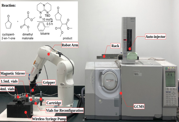
We propose to demonstrate the robot capabilities in a real organic chemistry experiment: the Micheal reaction. This reaction, a 1,4 addition to an -unsaturated carbonyl compound (Fig. 1), is an important reaction in organic chemistry. We follow the same steps and use the same setup as human chemist, more specifically:
-
1.
Liquid handling: The robot grabs the syringe pump and uses it to transfer liquids into a 1.5mL reaction vial;
-
2.
Mixing of chemicals: The robot picks the vial and brings it to a magnetic stirrer;
-
3.
Filtering: The robot pours the chemicals from a 1.5mL vial into a 3mL cartridge that is packed with silica and cotton for filtration. The cartridge is placed above an empty 1.5mL vial to store the filtered analyte sample;
-
4.
Integrating with GCMS: The robot brings the filtered analyte sample onto the rack of an auto-injector. which is mounted on a Gas Chromatography Mass Spectrometry (GCMS) machine;
-
5.
Reconfiguration: The robot reconfigures the environment in order to repeat the experiment;
-
6.
Analysis: The auto-injector administers analyte samples of the two runs into the GCMS for analysis to determine the yield.
The remainder of the paper is organized as follows. In Section II, we review previous works on automated chemical synthesis. In Section III, we presents the development of our system, which comprises: a robot arm, a parallel gripper, a specially-designed syringe pump. The syringe pump is a highlight of our setup: it was developed so as to deliver liquids with very high precision, while being manipulated by the robot in a flexible manner. We also show how to plan complex sequences of motions for the robot to perform the chemical experiment in a very fast manner. In Section IV, we describe the experiment and report the results, including the comparisons with junior and senior human chemists. Finally, in Section V, we conclude and sketch some directions for future research.
II Related Work
Li et al. [2] created an autonomous chemistry laboratory coupled with optimization algorithms to self-adjust the input parameters for given targets to derive new nucleation theories. A robot arm was used for object seeking and transferring of samples into the reaction chamber or the workstation. For liquid injection, a peristaltic pump that was installed on the reaction chamber was utilized.
Godfrey et al. [3] proposed an automated chemical synthesis laboratory which is capable of modular expansion and allows chemists to remotely guide chemical syntheses for drug discovery. Similar to [2], the robot arms were mostly used for pick-and-place operations, but also include diluting of samples which was briefly stated.
Williams et al. [8] developed a Robot Scientist to automate early stages of drug design, by randomly screening a subset of its library to filter suitable compounds and use AI to hypothesize Quantitative Structure Activity Relationship (QSAR). Resembling [2] and [3], the system included robot arms and they were used to transfer plates between different pieces of laboratory automation equipment.
In these papers [2], [3] and [8], it showed that robot arms were largely used to aid the operation of automation such as pick-and-place tasks, but the chemical syntheses were only conducted by the automation machines and not done by the robot arms.
The automation approach for these papers [4], [5] and [9] are quite similar as they made a single modular unit and pumps, valves and tubes were used instead of robot arms. For [4], [5], both studies had defined a chemical space or connectivity model consisting of a pool of reagents which were linked to the reactor while for [9], the solutions were loaded into cartridges that will be loaded to the synthesizer. The difference for each study is that, Steiner et al. [4] built a general synthesis unit that has a chemical programming language, which converts a typical reaction scheme into an executable code, that run sequential syntheses to produce drugs. Although Li et al. [9] also aim to have a generalized synthesizer, they specifically target the synthesis of small-molecules instead of drugs. On the other hand, Granda et al. [5] used random combinations of starting materials to perform reactions and then used AI to search for new reactivity within the chemical space.
Adamo et al. [6] demonstrated an industrial continuous flow manufacturing of Active Pharmaceutical Ingredient (API) that consisted of reconfigurable modules. The unit was differentiated into two streams, the upstream was for performing reactions and the downstream was for purification and formulation of the API. Continuous flow is created through pure automation and makes use of feeds and pumps to transfer chemicals, which is also evident in [10]. The continuous flow study conducted by Bedard et al. [10] was capable of optimizing a specific reaction or a sequence of reactions, synthesize a range of substrates under user-selected conditions or scale-up a previous optimized synthesis.
To automate the experiments in these papers [4], [5], [8] and [9], modifications such as sensors and tubing were made to most apparatus to facilitate liquid transfer and all components of the automation unit were dependent on each other. Hence, it will not be convenient to dismantle the unit to access any of these components individually due to the amount of tubing used. This accessibility may be desired by research chemists who share a common pool of equipment as by isolating equipment in the automation unit, it can result in a smaller amount of resources available. In addition, based on these studies, it is evident that most research involves pure automation and there were not many implementations of robotics. Robot arms were also mostly limited to pick-and-place tasks. However, robot arms may pose several advantages due to their flexibility and may be able to eliminate messy tubing to transfer liquids or apparatus. Hence, robot arms may allow the integration of independent equipment to automate chemical synthesis, such that the accessibility of these individual equipment can be retained.
III System Development
III-A Overall System
A Denso VS-060 robotic arm coupled with a Robotiq Hand-E gripper was operated in a structured environment to conduct the experiment. An automated and remote syringe pump was fabricated to perform liquid handling and a GCMS with model, Shimadzu GCMS-QP2010SE, was used for the analysis of the samples created by the robot.
III-B Development of Syringe Pump
Our syringe pump was developed based on the foundations of previous studies [12], [13]. Both papers adopted a similar approach, which was driving a stepper motor with a lead screw assembly. The motor was driven by a motor driver however, an Arudino micro-controller was used in [13] whereas a Raspberry Pi was utilized in [12]. They were both wired to a computer for control and both papers reported that their systems had high accuracy. In [12], it was reported that the accuracy of a NEMA11 motor was +/-1% and for the NEMA17 motor was +/-5% measured in 1mL increments and precision was relatively insensitive to microstepping for both motors. In [13], the study showed that a smaller syringe capacities had better performance as they resulted in smaller flow rate errors, and the flow rate errors for 0.5mL, 5mL and 60mL ranges from 0.5% to 3%. The main difference of our syringe pump design as compared to the previous studies in [12], [13] was that our design was remote whereas their designs had to be wired to a computer. In addition, our syringe pump was enclosed and contained the battery, electronics and mechanical components. This design also included a connection point so that the robot can grab the syringe pump and use it (Fig. 2). An external computer controlled the operations of both the robot and syringe pump via TCP communication such that the motions of both systems can be synchronized.
We created a similar system as [12], [13] and tested it on a 100L syringe, using a NEMA17 motor with Arduino Uno and a Raspberry Pi 2. It was observed that the Arduino system took 1s whereas the Raspberry Pi system took 23s to draw 10L when driven at 1/16 microstep. Thus, we decided to use a micro-controller instead of the Raspberry Pi in our design due to better performance. We also tested another micro-controller, the WeMos D1 Mini and noted that it achieved the same result as the Arduino. However, the WeMos D1 Mini was much smaller in size and had an ESP8266 module, thus enabling WiFi and Transmission Control Protocol (TCP) communication. Hence, it fits our system perfectly because the system had to be remote and battery operated for the robot arm to use.
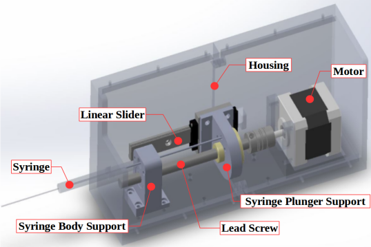
The pump consisted of 100L glass syringe and a bipolar NEMA17 stepper motor with 0.9∘ step angle with a lead screw assembly. The motor was controlled by a WeMos D1 Mini micro-controller and a Big Easy motor driver. A DC power shield was added to the micro-controller so that a 11.1V lithium ion battery could be used to power both the micro-controller and the motor driver which were placed in parallel. All connecting components were 3D printed and the assembly is shown in Fig. 2.
The motor was controlled at 1/16 microstep to reduce vibration and increase the resolution of the syringe. In [12], the study mentioned that accuracy of the assembly was found to be relatively insensitive to microstepping. Hence, these indicated that the syringe was able to accurately draw liquid at a better resolution than chemists. This enabled the experiment to be scaled down which reduced the amount of chemicals needed and a single syringe was able to cater to the required capacity.
III-C Motion Planning Procedure
The robot arm had numerous goal targets to reach to perform the experiment and each target had multiple solutions for the joint angles. As such, we require a sequence that could result in the shortest total trajectory time for all targets. A two-step algorithm, the Robotic Task Sequencing Program (RoboTSP), had been proposed by a previous study [14], to determine a near-optimal order of configurations for the manipulator to visit for n goal points, with m robot configurations per target. The outline of RoboTSP was to first, determine the visit sequence in task space and next, a graph search will be conducted to find the shortest path in configuration space based on the visit sequence.
However, the chemical experiment was made up of several sequential tasks and each task had n goal targets. As these sequential goal targets had a defined order, only the second step of RoboTSP was extracted to obtain the optimal sequence in the configuration space.
We came up with two different methods to acquire the optimal sequence by using RoboTSP as explained below (see Fig. 3):
-
1.
Get the optimal sequences of each individual task and concatenate them based on order of tasks. This meant that for x tasks, RoboTSP was ran x times.
-
2.
Concatenate the targets based on the order of tasks to obtain the optimal sequence in one sitting. In this case, RoboTSP was only ran once.
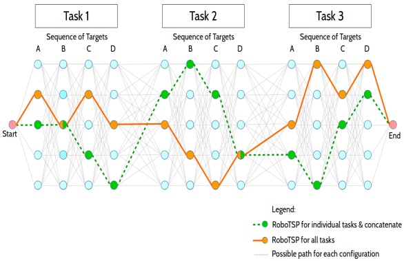
It was observed that the final sequence in Method 1 (dotted line) differs from Method 2 (continuous line), although there were some common configurations within the both methods, as illustrated in Fig. 3.
III-D System Integration
A system with Intel i7 2.20GHz processor and 8GB RAM, running Ubuntu 16.04 (Xenial) was used in this experiment. ROS was used to control both the Denso VS-060 robotic arm and the Robotiq Hand E gripper. The motion planning and collision checking was done in OpenRAVE.
IV Experiments
The Michael reaction protocol that was used in the experiment was extracted from [11]. The reaction was carried out in a 1.5mL vial where toluene, cyclopent-2-en-1-one, dimethyl malonate were reacted using TDB catalyst, and the reaction diagram can be seen in Fig. 1. The chemicals were stirred and subsequently added to ethyl acetate. The mixture was poured into a cartridge packed with silica powder for filtration and more ethyl acetate was poured to flush out the analyte sample.
IV-A Procedure
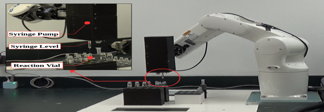
As presented in Section I, the detailed steps of the experiment are listed below (see Fig. 4):
Liquid Handling
The arm grabbed the syringe pump and used it to move reactants into a 1.5mL reaction vial, as shown in Fig 4a. Each time after a chemical was transferred, the syringe was flushed with acetone 5 times to wash it before a different chemical can be drawn by the syringe.
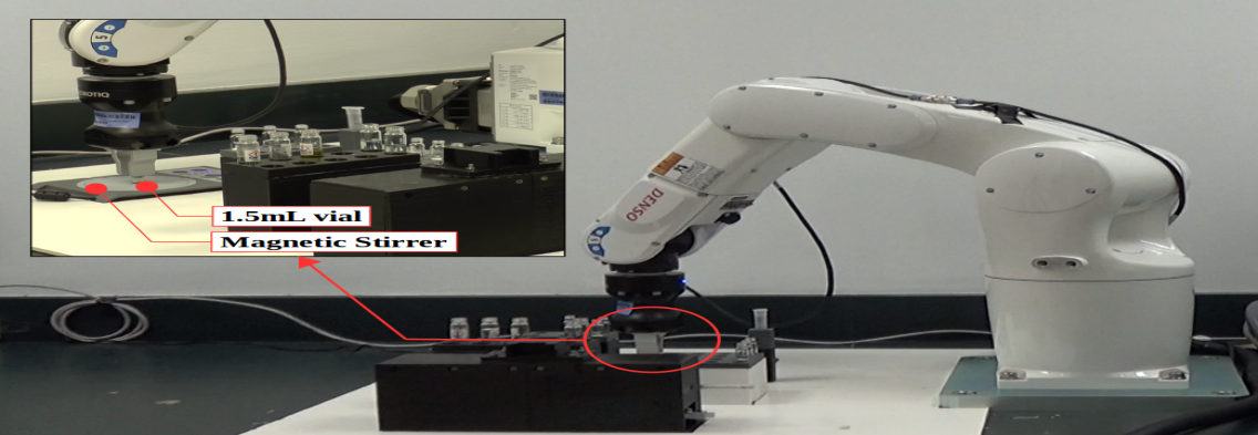
Mixing of chemicals
The arm picked the reaction vial, which contains a magnetic stir bar, and brought it to a magnetic stirrer to mix the chemicals, as shown in Fig 4b. The arm held the vial securely above the stirrer for 5 minutes and mixing was required to carry out the reaction. Once the reaction was completed, the arm brought the vial back onto the rack. Due to the dexterity of the robot, it eliminated the need of using a clamp to secure the vial above the magnetic stirrer.
Transferring reaction mixture
The arm grabbed the syringe pump again and used it to add reaction mixture from the 1.5mL reaction vial to another 1.5mL vial containing ethyl acetate. This was to dilute the analyte sample to meet the concentration requirements of the GCMS and also to standardize the volume of reaction mixture used for analysis in each run.
Mixing of chemicals
The vial with ethyl acetate and reaction mixture also contains a magnetic stir bar, and the arm brought the vial to the magnetic stirrer for 5 minutes.
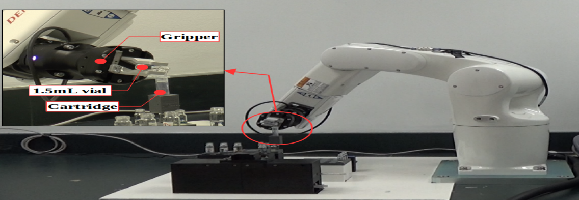
Filtering
Filtration was required to remove the catalyst from the mixture. The arm grabbed a silica-packed 3mL cartridge which was seated in a holder, and placed it on top of an empty 1.5mL vial. Filtration was done by using the arm to pour chemicals from the vial containing reaction mixture into the 3mL cartridge, as shown in Fig 4c. The arm then waited 5 minutes for the filtration by gravity to be completed. An additional 1.5mL vial with only ethyl acetate was poured into the cartridge as well to flush out the analyte sample. The arm waited another 5 minutes for the filtration to be completed. The trajectory for pouring was done by bringing the end-effector to the rim of the cartridge, and applying Cartesian twists to the end-effector to create the pouring action. The twists were applied gradually, which meant that the pouring action did not only make up of a single twist, but multiple twists. As one of the vials used for pouring contains a magnetic stir bar while the other vial did not, the Cartesian twists applied were different because the stir bar was obstructing the flow. Thus, the twists had to be more gradual for the vial with the stir bar to prevent spillage even though the total twists for both vials were rather similar. The total twist applied for the first vial with the stir bar was at 122∘ and x=203mm towards the cartridge whereas for the second vial, the angle was 118∘ and x=201mm. These twists were determined through experimenting.
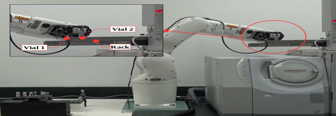
Integrating with GCMS
The arm brought the filtered analyte sample onto the rack of an auto-injector which was mounted on the GCMS, as shown in Fig 4d. The trajectory this step was done by planning with constraints on the x, y, z axes of the gripper as the vial was not capped. Hence, these restrictions on the end-effector was to prevent obtaining a trajectory that could cause the vial to turn upside down and result in spillage.
Reconfiguration
The arm reconfigured the environment and Steps 1-5 were repeated. The newly filtered analyte sample was placed on another hole of the rack of the auto-injector.
Analysis
The auto-injector was activated and it administered both analyte samples into the GCMS for analysis to determine the yield of the sample. The GCMS took 30 minutes including cooling, to analyze each run.
Hence, each experiment consisted of 2 runs, which yielded 2 vials of analyte samples. The only difference between Run #1 and Run #2 was the extra reconfiguration step which was present in Run #2.
IV-B Specifications
The specifications for each run are listed in Table I. The offline planning time was the total time taken to obtain the optimized sequence from RoboTSP, which was discussed in Section III-C, and plan trajectories to these configurations for all tasks.
The number of planned trajectories corresponds to the number of joint configurations from the optimized sequence, however the actual number of trajectories executed were more than the number of planned trajectories, as some trajectories were repeated during washing of syringe in the liquid handling step. The actual execution time consisted of the time taken for the robot to execute trajectories and the time taken for the syringe to draw and push liquid, which did not include waiting time. As the total waiting time consisting of the stirring time and filtration time amounted to 20 minutes, the total time for Run #1 and Run #2 was approximately 30 minutes and 31.5 minutes respectively.
| Specifications | Run #1 | Run #2 |
|---|---|---|
| Offline Planning Time (s) | 17 | 20 |
| No. of Tasks | 19 | 20 |
| No. of Planned Trajectories | 109 | 151 |
| Actual Execution Time (minutes) | 10 | 11.5 |
IV-C Results
Motion Planning Results
As discussed in Section III-C, there were two proposed methods in obtaining the optimal sequence. We did a comparison on planning duration for 5 tasks between both methods, as shown in Table II.
| Planning Time (s) | Trajectory Duration (s) | |
|---|---|---|
| Method 1 | 4.1 | 88.4 |
| Method 2 | 2.3 | 70.0 |
The planning time is the total time taken to plan to all joint configurations of every task and the trajectory duration is the total time taken to execute all trajectories of every tasks. The planning time and trajectory duration in Method 1 was longer by 77% and 26% respectively, as compared to in Method 2. This indicated that the sequence obtained from Method 1 was less optimal as compared to Method 2. Therefore, we used Method 2 to obtain the optimal sequence and compute the offline planning time in Section IV-B.
Synthesis Results
The GCMS was ran under the following conditions:
-
•
Restek Rtx-5MS, 30m x 0.23 mmID, x 0.25 m df column.
-
•
Hold at 60∘C for 3 minutes and heat at 6∘C/min to 180∘C.
-
•
Pressure at 56.7kPa, column flow 0.99mL/min, split injection mode, split ratio:100.
-
•
Injection port temperature at 250∘C.
-
•
Ion source temperature at 200∘C, pressure at 56.7kPa, m/z 60-250.
| Concentration (mg/mL) | Yield (%) | |
|---|---|---|
| Experiment 1, Run #1 | 6.47 | 24 |
| Experiment 1, Run #2 | 8.11 | 30 |
| Experiment 2, Run #1 | 9.90 | 37 |
| Experiment 2, Run #2 | 8.30 | 31 |
| Junior chemist | 9.89 | 36 |
| Senior chemist | 14.45 | 54 |
The analyte samples created by the robot in Experiments #1 and #2 were sent for analysis. From the analysis in Table III, it proved that the robot was capable of conducting chemical synthesis. The average yield for Run #1 of both experiments was 30.5%, and the average yield for Run #2 was also 30.5%. In addition, the overall mean yield across both experiments was 30.5% too. The concentration is directly proportional to the yield and is dependent only on the yield. Hence, the average concentration across all runs was 8.2mg/mL of analyte sample.
We also showed that the robot arm had the ability to perform reconfiguration and repeat the experiment, which was due to its dexterity. This indicates the possibility of implementing AI into the experiment to optimize reactions. Once an optimized reaction had been found, the robot would be able to reproduce a similar optimized result by repeated the experiment, due to its ability to achieve consistent results.
We also compared the yield obtained by the robot to those obtained by a junior chemist (undegraduate student in Chemistry) and a senior chemist (postdoctoral researcher). The chemicals used were of the same batch of chemicals that was used in Experiment 2 conducted by the robot.
IV-D Discussion
From the analysis in Table III, it showed that the robot was capable of achieving consistent yield for both runs of each experiment, even though the Experiments 1 and 2 were conducted on separate instances and a new batch of chemicals was used for each experiment. The batch of chemicals that were used evidently affects the yield to a certain extent which can be seen by comparing Experiments 1 and 2. The runs in Experiment 2 had a generally higher yield as compared to Experiment 1 although the average yield across the run numbers were the same.
The analysis also illustrated that the robot could obtain a similar yield as a junior chemist (34% versus 36%). The comparison was done in this matter such that it would be fair, since the batch of chemicals used can affect the results to a certain extent, which was discussed in the previous analysis. However, we observed that the yield achieved by the senior chemist was higher than that of the robot, which may be due to the high skills of the senior chemist, achieved through years of training. One possible improvement could be for example in the liquid transfer step: during the transfer, chemicals may stick onto the walls of the vials, leading to lesser amount of reactants, hence a lower yield. Understanding the skills of the senior chemist and transferring them to the robot would be a very exciting direction of research.
V Conclusions
We have looked into the feasibility of automating chemical synthesis using a robot arm and achieved an average yield of 30.5% and an average concentration of 8.2mg/mL of analyte sample formed. The experiment proved that robot arms have the ability in automating experiments and are not limited to pick-and-place tasks which was seen in previous studies. Taking advantage of the dexterity of the robot, we were able to integrate independent systems together to carry tasks to complete the experiment. The tasks executed by the robot include using the syringe pump to transfer liquids, doing pouring, bringing the reaction vial to the stirrer and to the auto-injector rack. In conclusion, based on the advantages attributed to robot arms such as consistency of results and abilities to integrate independent systems together, robot arms can be used to automate chemical syntheses.
We envision three main lines of future research. First, we can improve the yield and repeatability of the reactions by better understanding the skills of the senior chemist and transferring them to the robot. Second, we can add new skills to the robot, in order to perform more complex reactions, by implementing mechanisms for learning from human demonstration. Finally, as we have demonstrated that the robot can autonomously perform two runs, it can be easily extended to perform multiple runs. This opens the possibility of using Machine Learning techniques to learn optimal reaction parameters by performing the experiment multiple times. Our future work will explore this exciting avenue.
Acknowledgment
This work is supported by Nanyang Technological University (M4012040) and Ministry of Education.
References
- [1] M. Trobe and M.D. Burke, ”The Molecular Industrial Revolution: Automated Synthesis of Small Molecules,” Angew. Chem. Int. Ed., vol. 57, no. 16, pp. 4192-4212, 2018.
- [2] J. Li et al., ”AIR-Chem: Authentic Intelligent Robotics for Chemistry,” J. Phys. Chem. A, vol. 122, no. 46, pp. 9142-9148, Nov 2018.
- [3] A.G. Godfrey, T. Masquelin and H. Hermerle, ”A remote-controlled adaptive medchem lab: an innovation approach to enable drug discovery in the 21st Century,” Drug Discovery Today, vol. 18, no. 17/18, Sep 2013.
- [4] S. Steiner et al., ”Organic Synthesis in a modular robotic system driven by a chemical programming language,” Science, vol. 363, no. 144, Jan 2019.
- [5] J. M. Granda, L. Donina, V. Dragone, D.L. Long and L. Cronin, ”Controlling an organic synthesis robot with machine learning to search for new reactivity,” Nature, vol. 559, pp. 377-381, Jul 2018.
- [6] A. Adamo, et al., ”On-demand continuous-flow production of pharmaceuticals in a compact, reconfigurable system,” Science, vol. 352, no. 6281, pp. 62-68, Apr 2016.
- [7] F. Suárez-Ruiz, X. Zhou and Q.C. Pham, ”Can robots assemble an IKEA chair?,” Science Robotics, vol. 3, no. 17, Apr 2018.
- [8] K. Williams, et al., ”Cheaper faster drug development validated by the repositioning of drugs against neglected tropical diseases,” J. R. Soc. Interface, vol. 12, no. 20141289, Jan 2015.
- [9] J. Li, et al., ”Synthesis of many different type of organic small molecules using one automated process,” Science, vol. 347, no. 6227, pp. 1221-1226, Mar 2015.
- [10] A.C. Bedard, et al., ”Reconfigurable system for automated optimization of diverse chemical reactions,” Science, vol. 361, no. 6408, pp. 1220-1225, Sep 2018.
- [11] W. Ye, J. Xu, C.T. Tan and C.H. Tan, ”1,5,7-Triazabicyclo[4.4.0]dec-5-ene (TBD) catalyzed Michael reactions,” Tetrahedron Letters, vol. 46, no. 40, pp. 6875-6878, Aug 2005.
- [12] B. Wijnen, E.J. Hunt, G.C. Anzalone and J.M. Pearce, ”Open-source Syringe Pump Library,” Plos One, vol. 9, no. 9, Sep 2014.
- [13] H. Coskun, O. Gul, O. Ferhanoglu and Y.D. Gokdel, ”Design and Implementation of a Low-Cost High-Performance Syringe Pump System,” 2017 21st National Biomedical Engineering Meeting, 2017.
- [14] F. Suarez-Ruiz, T.S. Lembono and Q.C. Pham, ”RoboTSP - A Fast Solution to the Robotic Task Sequencing Problem,” 2018 IEEE Internation Conference on Robotics and Automation (ICRA), pp. 1611-1616, May 2018.