gbsn
Shell potentials for microgravity Bose-Einstein condensates
Abstract
Extending the understanding of Bose-Einstein condensate (BEC) physics to new geometries and topologies has a long and varied history in ultracold atomic physics. One such new geometry is that of a bubble, where a condensate would be confined to the surface of an ellipsoidal shell. Study of this geometry would give insight into new collective modes, self-interference effects, topology-dependent vortex behavior, dimensionality crossovers from thick to thin shells, and the properties of condensates pushed into the ultradilute limit. Here we discuss a proposal to implement a realistic experimental framework for generating shell-geometry BEC using radiofrequency dressing of magnetically-trapped samples. Such a tantalizing state of matter is inaccessible terrestrially due to the distorting effect of gravity on experimentally-feasible shell potentials. The debut of an orbital BEC machine (NASA Cold Atom Laboratory, aboard the International Space Station) has enabled the operation of quantum-gas experiments in a regime of perpetual freefall, and thus has permitted the planning of microgravity shell-geometry BEC experiments. We discuss specific experimental configurations, applicable inhomogeneities and other experimental challenges, and outline potential experiments.
I Introduction
The study of quantum-degenerate ultracold atomic gases has historically been guided by explorations of geometry, dimensionality, topology, and interaction. Whenever the parameter space of dimensionality and geometry has been expanded, interesting physics has typically been unveiled. Studying Bose-Einstein condensates (BECs) in 2D has yielded insight into quasi-condensation and the BKT transition Desbuquois:2012fh; Ha:2013jr; Hadzibabic:2008eo, and in 1D insight into fermionization and many-body systems out of equilibrium Hofferberth:2007fk; Kinoshita:2006p765; Kinoshita:2004jp . Exploring toroidal condensates has driven progress in understanding persistent currents and uncovered links to cosmological inflation Eckel:2018gv; Mathew:2015gg, and double-well condensates have been used for many applications including matter-wave interferometry and spin squeezingSchumm:2005lr; Esteve:2008cl. A shell- or bubble-geometry BEC, while physically interesting due to its distinct topology, has not been physically realized due to the distorting influence of gravity on typical atom traps. In this work we present modeling related to proposed experiments with bubble-geometry BECs aboard the NASA Cold Atom Laboratory (CAL), currently in operation aboard the International Space Station (ISS).
An experimental path to creation of shell potentials for BECs was proposed not long after the first creation of BEC itself, focusing on so-called adiabatic potentials created with radiofrequency-dressed magnetic traps PhysRevLett.86.1195, discussed further in Section II. Alternate schemes for the study of shell BECs have focused on the specific study of the superfluid shells in optical-lattice Mott-insulator systems barankov:063622, or in the exotic environment of a neutron star Pethick:2015ta. More recent theoretical work has focused on the collective modes of shell condensates, and the signatures of a condensate transitioning to a hollow shell from a conventional topology Sun:2018de; Padavic:2017cv. Interesting effects are predicted to occur when a shell condensate is released into time-of-flight expansion; different regions of the shell BEC will interfere with each other, resulting in spatial matter-wave interference patterns that are quite sensitive to the shape of the shell potential and (via mean-field interactions) the number of atoms in the condensate Lannert:2007kk. Recent work has also been done exploring the basic physics of BEC on the surface of a sphereTononi:2019us; Bereta:2019th.
Further, the motivation for the study of shell-shaped condensates stems from the drastic change in topology associated with expansion into a shell; vortex behavior (for example) shows promise as an avenue of investigation, including the potential study of vortex lattices in a curved background. Vortices in a shell-shaped condensate will behave in a qualitatively different manner than those in a flat condensate (such as a disk) because of the curvature of the shell surface and because of the topology of the shell as an unbounded simply-connected surface. Previous theoretical work has predicted that a single pair of vortices on the surface of a sphere will repel and therefore arrange themselves at polar-opposite points Milagre:2007jt. Vortices in the shell-condensate system can be induced through rotations or, if the shell is thin enough, they will be spontaneously produced near the thermal transition to a non-condensed gas Hadzibabic:2006lr. The effect of curvature on vortices in a thin condensate is a richer area for exploration; for example, defects (such as vortices) on a curved surface experience a force due to the local curvature Turner:2010kl; Vitelli:2004gv.
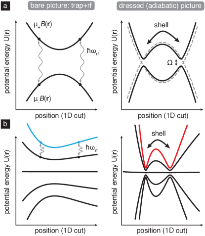
II Radiofrequency dressing
The interaction of radiofrequency (rf) or microwave radiation with a set of Zeeman-split hyperfine manifolds is a well-studied system that is often characterized in terms of dressed states, which in the case of inhomogeneous magnetic fields such as found in magnetic traps result in so-called adiabatic potentials Garraway:2016hu; perrin2017trapping. Figure 1 illustrates the general idea of radiofrequency dressing; lower-lying adiabatic potentials are associated with the “rf knife” techniques of evaporative cooling in magnetic traps, while the higher-lying adiabatic potentials can be understood as double-wells in 1D, ring potentials in 2D, and shell potentials in 3D, as first proposed by Zobay and Garraway zobay:023605; PhysRevLett.86.1195; Zobay:2000tk. Experimentally, ultracold gases in rf-dressed shell potentials were first generated with the key observation that gravitational sag caused the shell-trapped samples to localize near the bottom of the shell potential white:023616; perrinbec; indeed, this localization could be considered a feature due to the possibilities of applying it to studies of effectively 2D quantum gases Merloti:2013ft.
To calculate the dressed potentials associated with a single driving frequency of coupling strength , we operate in the usual rotating frame perrin2017trapping and take the rotating-wave approximation resulting in the Hamiltonian
| (1) |
where is diagonal and represents the (exact) Zeeman shifts of the states in use, which for the purposes of this work are the 87Rb upper hyperfine ground state denoted by , with taking values from -2 to 2. Modeling of terrestrial experiments would require the addition of an term to . The spatially-varying eigenvalues of the Hamiltonian in Eq. 1 represent the adiabatic potentials and the eigenvectors represent the spatially-varying decomposition of the dressed state in the lab-spin basis.
The detuning of the rf field acts to control the mean radius of the bubble potential, and the coupling strength (which could have some weak spatial dependence) serves the twofold purpose of controlling the curvature of the local bubble minimum but also ensuring (through sufficiently large magnitude) stability against Landau-Zener-type nonadiabatic losses in this dressed-state picture. These losses have been explored in the context of magnetic traps Burrows:2017bw and also connected to the stability of condensates in radiofrequency-dressed spin-dependent optical lattices Lundblad:2014cc; Lundblad:2008kb.
III Cold Atom Laboratory (CAL) Apparatus
The rf-dressing process resulting in shell-like BEC could be performed in any ultracold atomic physics experimental framework featuring magnetic trapping and elimination of gravitational perturbation, and thus could be implemented in drop-tower Muntinga:2013ge; VanZoest:2010p3350, ballistic aircraft Barrett:2016ko, or the most recently developed sounding-rocket Becker:2018db configurations (the latter representing the first BEC experiment in space). Our investigation has focused on planned experiments aboard the NASA Cold Atom Laboratory (CAL). CAL was developed by the Jet Propulsion Laboratory (JPL) beginning in 2013 and is currently in operation aboard the International Space Station (ISS) after a 2018 delivery via a Cygnus spacecraft launched from NASA’s Wallops Flight Facility. CAL is an atom-chip-based BEC machine equipped with a variety of experimental degrees of freedom permitting operation with multiple experimental PIs with a diversity of experimental frameworks, including Efimov physics Mossman:2016vpa, adiabatic expansion and delta-kicked cooling to pK temperatures Sackett:2017gp; Myrskog:2000il, novel atom lasers Meister:2019bv, and ongoing development of atom-interferometer capabilities.
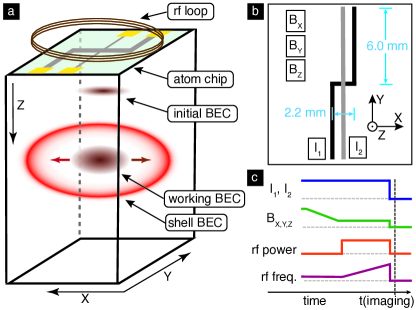
General capabilities of the instrument (see accompanying illustrations in Fig. 2) include providing 87Rb BECs with in an initial high-aspect ratio trap configuration with approximate trap frequencies Hz, where is the direction perpendicular to the atom chip and is the direction associated with the bias magnetic field at trap bottom. Condensates are obtained via rf evaporation of a sample held in the magnetic trap formed by a combination of currents flowing through the atom-chip wires and three quasi-uniform external bias fields. Details of system development and ground test status can be found in Ref. Elliott:2018dk. Specific design input was sought from prospective users; for example, significant guidance regarding the rf system design of dressed-atom experiments can be found in the literature, specifically focusing on the need for DDS signal sources and very fine-grained frequency ramps during the dressing process in order to avoid excess heating Morizot:2008bq. A key capability to begin dressed-atom experiments with CAL is the generation of traps of lower density and aspect ratio; hence, a trap expansion protocol that does not incur unwanted center-of-mass motion is desired. Such paths have been developed in the context of shortcuts to adiabiaticity with drop-tower missions Corgier:2018iu and in planning for CAL; we have developed expansion ramps roughly in the form of a hyperbolic tangent, following the formalism of Ref. Sackett:2017gp.
The general procedure for forming a shell condensate in a machine such as CAL would be as follows, as parametrized in Fig. 2(c). First, the condensate would be prepared in a given initial starting condition (the “bare trap”, in the internal state ), at which point the rf dressing signal would be switched on with the detuning negative and large compared with the Rabi frequency , where is associated with magnetic resonance at trap bottom. Secondly, the rf frequency would be ramped upwards, forcing the condensate in the uppermost adiabatic potential into a shell geometry. The timescale of this ramp would be enforced by mechanical adiabaticity of the BEC deformation and technical limits on the graining of the rf signal; timescales associated with motion perpendicular to the local shell surface are easily satisfied, but adiabaticity with respect to motion around the shell remains an open question. Coupling strengths 10 kHz are appropriate for these scenarios, chosen in the context of the suppression of Landau-Zener losses Merloti:2013ft; this rf amplitude is well within the documented capability of the CAL instrument.
IV Ground state & inhomogeneities
Following the formalism summarized by the Hamiltonian in Eq. 1 we calculate adiabatic potentials for several different cases of interest. In particular, it is useful to investigate the effects of rf detuning and atom number on the planned experiments, and explore the consequences of various inhomogeneities associated with the experiment. The most dominant inhomogeneity associated with such experiments on Earth is gravitational potential energy (absent in Eq. 1), which for 87Rb corresponds to a tilt of 2.14 kHz/m (or 103 nK/m). Taken into account across a typical condensate profile, this dwarfs the ability of BEC interaction energy to “fill up” a gravitationally tilted shell. In freefall this effect is absent and we are left with several confounding factors orders of magnitude smaller, framed as follows: inhomogeneity A, associated with the ellipsoidal aspect ratio of the shell potential, inhomogeneity B, associated with the wandering of the local magnetic field direction across the trapped atomic cloud (impacting dressing via departure from orthogonality with the dressing field), and inhomogeneity C, associated with the difference in across the sample.
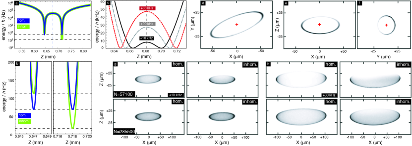
While slices of condensate density along principal directions are useful modeling checks, experimental data will come in the form of column density along a particular direction. Fig. 3 shows calculated condensate density slices (3d–f) and column densities (3g–h) for planned magnetic field configurations. The example trap chosen has identical atom-chip currents to the “tight trap” where the CAL BEC first forms, but has had external bias field reduced to 0.2 their initial value, resulting in trap frequencies of approximately (30, 100, 100) Hz as suggested by our model and by initial calibration experiments aboard CAL. Also shown are examples of column densities taken without accounting for the inhomogeneities A, B, C as defined above, to illustrate their impact. The coupling-related inhomogeneity C pulls the condensate toward (away from the chip); inhomogeneity B pulls toward , and inhomogeneity A results in pooling of atoms at the tips of the trap ellipsoid.
Condensate densities are calculated using an imaginary-time propagation-based Gross-Pitaevskii solver Chiofalo:2000ky; Cerimele:2000hs using the uppermost dressed-stated potential as input, along with illustrative condensate numbers chosen to be different by a factor of 5 and consistent with CAL specifications. These calculations confirm typical intuition, that the Gross-Pitaevskii nonlinearity driven by repulsive atom-atom interaction (i.e. the chemical potential ) serves to some degree to conceal nonuniformities that are of order . However, this benefit is limited; the ground-state energies associated with the the scenarios in Fig. 3(g-h) range from 100–200 Hz (or 5–10 nK), an order of magnitude smaller than the ground-state energy of the original condensates. In general, atom number is not large enough in the CAL scenario to drive a shell-trapped condensate into the interaction-dominated Thomas-Fermi regime. Nevertheless, the Gross-Pitaevskii ground states show that a shell-trapped BEC (of size m) is within the capabilities of the CAL system to observe, with the caveat that complete density coverage around the surface of the shell will be strongly sensitive on the atom number made available. The effects of terrestrial gravitational tilt is absent in these plots, given the planned microgravity environment; were it present, the modeled clouds would be very strongly pinned to one end of the trap as in the terrestrial experiments Harte:2018jm; white:023616; perrinbec. The significant inhomogeneity C (that of the rf coupling) can be reduced to some degree by moving to lower absolute coupling strength, given that the tilt is proportional to ; this would be at the eventual cost of reduced dressed-state lifetime due to Landau-Zener nonadiabaticity. For future experiments, it also could be mitigated through experimental design (e.g., rf loop radius and placement).
V Future prospects
Following five years of development, NASA CAL was recently commissioned aboard ISS after 2018 launch. It has undergone testing and is in active user-facility mode with several PI groups, including the authors. Initial work will focus on calibration of the various models used to predict trap fields, trap frequencies, and other properties of the atom-chip system, followed by exploration of residual motion in given trap configurations where the magnetic trap has been expanded and translated away from the chip surface. Assuming sufficiently stable BEC production, stable trap position, and repeatable magnetic resonance observations, rf dressing of the CAL atom-chip trap is within reach.
Beyond confirmation of shell structure the microgravity BECs, discovery-oriented user time will focus on elucidation of the adiabaticity requirements of shell creation, possible exploration of collective-mode dynamics, and studies of the lifetime of BEC shell structures. We also anticipate observation and characterization of the inhomogeneities predicted and discussed in Section. IV, and exploration of the behavior of non-condensed thermal atoms in the dressed potential, depending on what condensate fractions are available on orbit. To frame future design considerations, we note that shell thickness might potentially be tunable through use of the nonlinear Zeeman shift SinucoLeon:2012bl, and that the inhomogeneity associated with the rf loop could potentially be compensated through application of a similarly inhomogeneous microwave dressing field, i.e. a compensatory ac Zeeman shift SinucoLeon:2019ue; Garraway:dikHLmv0.
CAL is currently scheduled to remain in operation until late 2019, whereupon a major hardware replacement is scheduled to occur, after which the facility should return to user-facility operations for additional time. A second-generation orbital microgravity atom-chip ultracold atomic physics facility, BECCAL, is currently under development of in Germany as a joint DLR/NASA venture Becker:2018vc. This successor machine should share CAL’s capabilities for generation of rf-dressed systems, enabling a second-generation exploration of shell-BEC physics.