Surface polaritonic solitons and breathers in a planar plasmonic waveguide structure via electromagnetically induced transparency
Abstract
We propose a scheme for the coupler-free excitation of surface polaritonic solitons and breathers in a planar plasmonic waveguide structure comprising of a transparent layer, a metal layer and a layer of three-level lambda-type atomic medium. In the proposed system, an enhanced Kerr nonlinearity is achieved via electromagnetically induced transparency (EIT) in the bottom atomic medium, which can be controlled through proper modulation of the frequency detunings and Rabi frequencies of the driving laser fields. This nonlinearity balances the dispersion in the system, thus providing the necessary condition for the excitation of polaritonic solitons in the proposed system. As a result, the system yields laterally self-trapped bright and dark surface polaritonic solitons which are tightly guided at the interface of the metal and the EIT medium. Furthermore, we investigate the excitation of surface polaritonic Akhmediev breathers at the metal-EIT medium interface in the proposed system. A stable propagation of the surface polaritonic Akhmediev breathers is achieved with proper choice of parameters in the proposed planar plasmonic waveguide structure. This experimentally feasible scheme could be significant in the development of highly compact nano-photonic devices in the optical regime.
- PACS numbers
I Introduction
Over the past decades, the electromagnetically induced transparency (EIT) phenomenon has garnered a lot of attention due to its potential applications in the efficient control of optical properties in atomic media fleischhauer2005electromagnetically ; marangos1998electromagnetically ; lukin2001controlling ; phillips2001storage ; li1996enhancement ; braje2004frequency . EIT is a quantum phenomenon that usually occurs as a result of destructive interference between two transition pathways of an atomic medium, resulting in the elimination of the absorption in the medium fleischhauer2005electromagnetically ; marangos1998electromagnetically . It should be noted that the optical response of the medium is greatly modified within the EIT transparency window schmidt1996giant . Numerous interesting studies have been performed, to utilize the key aspects of the EIT phenomenon such as the tunable transparency window, steep dispersion, enhanced nonlinearity, etc. for the realization of various applications such as slowing of light lukin2001controlling ; phillips2001storage and nonlinear processes braje2004frequency ; li1996enhancement , etc. A plethora of theoretical and experimental studies have also been performed to study the optomechanical wang2014optomechanical ; safavi2011electromagnetically and metamaterial analogues zhang2008plasmon ; papasimakis2008metamaterial ; devi2017plasmon ; devi2018plasmon ; mahat2017plasmonically of the EIT phenomenon. Recently, the EIT phenomenon has also been associated with the generation of surface plasmon (SP) resonances in planar waveguide structures du2012quantum ; shen2014electromagnetically . SPs are electromagnetic surface modes enabling effective localization of light over subwavelength dimensions maier2007plasmonics , and have been studied extensively over the years, owing to its various applications in subwavelength control of light shalaev2006nanophotonics ; gramotnev2010plasmonics ; schuller2010plasmonics ; poudel2018active , bio-sensing wu2010highly , solar cells zhang2012surface ; catchpole2008plasmonic ; ferry2010light , etc. The unification of the EIT phenomenon and SPs excitation has paved the way for several studies in the recent years. Theories have been proposed for the generation of SP resonances in a system of a prism-coupler with a lambda-type EIT medium du2012quantum as well as a four-level tripod EIT system shen2014electromagnetically . The propagation of ultraslow SPs have also been examined in a recent study, in a grating coupled planar waveguide structure via the EIT phenomenon ziemkiewicz2018ultraslow .
In 2015, a novel study performed by Du et.al revealed the possibility of exciting SP resonances without the use of any coupler at the interface of a metal and an EIT medium du2015coupler . Other studies have also been performed by Bai et. al, in which they reported the excitation of plasmon-solitons bai2015giant and dromions bai2016plasmon in metamaterials (MMs) by utilizing the analog of EIT phenomenon in MMs. Recently, a coupler free scheme for SPs excitation at the interface of a negative index metamaterial (NIMM) and a four-level EIT medium has also been studied, along with the behavior of the SPs in the non-linear regime asgarnezhad2017coupler ; asgarnezhad2018excitation . In the non-linear regime, the dynamics of the excited SPs is governed by the so-called non-linear Schrodinger equation (NLSE), which can assume different exact solutions (e.g. solitons, breathers and rogue waves) boyd2003nonlinear ; drazin1989solitons . The SPs in the non-linear regime, inherit the properties of these nonlinear waves such as stable propagation, shape preservation, modulation instability feigenbaum2007plasmon ; marini2011stable ; kumar2017spatial ; devi2018surface , etc. Hence, there is a significant potential of such nonlinear SP waves as it can be employed as a means to reduce the propagation loss inherent in SPs. Additionally, the coupler-free scheme can become a promising technique for the development of highly compact nano-optical devices for various applications in the optical regime by overcoming the limitation faced by the SP coupling techniques. However, only few studies on coupler-free excitation of the nonlinear SP waves has been reported so far asgarnezhad2017coupler ; asgarnezhad2018excitation ; dong2018matching . Therefore, more studies are required to have a better understanding of the non-linear dynamics of the surface polaritonic solitons and breathers in such coupler free schemes.
In this article, we propose a scheme for the coupler-free excitation of surface polaritonic solitons and breathers in a planar plasmonic waveguide structure comprising of a transparent layer, a metal layer and a three level lambda-type EIT medium. Although, similar studies have been performed earlier asgarnezhad2017coupler ; asgarnezhad2018excitation , the nonlinear behavior of the SPs using a coupler-free scheme with a three-level EIT medium has not been investigated. Further, we have used a metal layer in our study, unlike the studies reported in ref. asgarnezhad2017coupler ; asgarnezhad2018excitation where a NIMM layer is used. To the best of our knowledge, the excitation and propagation of the surface polaritonic solitons and breathers remained to be explored in our proposed structure. Here, we explore the nonlinearity aspect associated with the EIT phenomenon to investigate the generation of surface polaritonic solitons and breathers in the proposed structure. It is observed that within the EIT transparency window, a giant Kerr nonlinearity is achieved which can be efficiently controlled through proper modulation of the parameters of the incident fields. A balance between the group velocity dispersion (GVD) and the Kerr nonlinearity in the system provides the necessary condition for the excitation of nonlinear SP waves. It is observed that the system yields laterally self-trapped surface polaritonic solitons which is tightly guided at the interface of the metal and the EIT medium. Further, we explore the possibility of generating surface polaritonic breathers in the proposed system. We show that the surface polaritonic solitons and breathers can have an undistorted and a stable propagation at the interface of the metal-EIT medium. The paper is organized as follows: In section 2, the theoretical model of the coupler free scheme based on EIT is explained. The coupler free excitation of SPs in the proposed structure is discussed in section 3. Section 4 explains the excitation and propagation of the surface polaritonic solitons in the nonlinear regime. In section 5, the excitation and propagation of the surface polaritonic Akmediev breather is discussed followed by a brief conclusion in section 6.
II Theoretical model
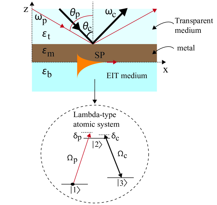
The schematic diagram of the proposed planar plasmonic waveguide structure based on EIT is illustrated in Fig. 1. The structure comprises of three layers namely, a top transparent layer, a middle metal layer and a bottom layer of EIT medium. The top layer is a transparent medium (vacuum or a lossless dielectric) having a refractive index, , where and are the electrical permittivity and magnetic permeability of the medium, respectively. The middle layer is considered to be a metal having a permittivity, while the bottom layer is a three-level lambda type EIT medium with electric permittivity, . The levels , and denotes the energy levels of the lambda-type atomic system in which the transition between the levels and is driven by a weak probe field of angular frequency, and the transition between the levels and is driven by a strong coupling field of angular frequency, . and denotes the Rabi frequencies associated with the probe and coupling fields with frequency detunings and , respectively. The dynamics of the three-level lambda-type atomic medium is given by the Maxwell Bloch equations wang2001enhanced ; van2015eit . Using the dipole and the rotating wave approximations, the equation of motion of the medium can be described by the density matrix equations as follows:
| (1a) | ||||
| (1b) | ||||
| (1c) | ||||
| (1d) | ||||
| (1e) | ||||
| (1f) | ||||
Under the slowly varying approximation, the evolution of the weak probe field in the system which is given by the Maxwell Equation, as
| (2) |
where, is the coupling coefficient. is the atomic density of the atomic medium, is the dipole moment of the transition (for ), is the absolute electric permittivity. is the effective refractive index of the system. Here, the dielectric constant of the medium can be obtained with effective-medium theory, as
| (3) |
where, is the effective susceptibility of the medium which is expanded to the third order, bass1995handbook as follows:
| (4) |
III Coupler-free excitation of surface plasmons in the linear regime
In the linear regime, the density matrix elements and the probe field could be expanded using the perturbation method van2015eit as and , respectively where is the perturbation parameter. Moreover, we consider , and , where is a constant describing the pulse envelope of the SPs and , with as the frequency perturbation of the SP and the linear dispersion of the atomic medium is given by
| (5) |
By assuming a weak field limit of the incident probe field, we have , and . Using these conditions, we can obtain the expression for to the first order as follows:
| (6) |
Then, the linear susceptibility of the atomic medium is given by
| (7) |
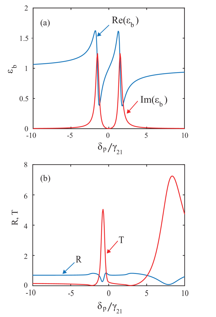
In the proposed scheme, the excitation of surface plasmon polaritons can be explained with the help of the transmittance and the reflectance of the three-layer structure. Following the method described in ref du2015coupler , the transmittance and the total reflection is calculated using the expressions, and , respectively, where and are the three-layer transmission and the reflection coefficients of the three-layer structure. The normal wave vectors is given by where while the parallel wave vector is given by , where is the vacuum wave number and is the incident angle of the probe field. The relative permittivity and the excitation of the SP resonance is depicted in Fig. 2. Figure 2(a) represents the real and imaginary part of the relative permittivity while Fig. 2(b) represents the transmittance and the reflectance of the proposed structure. Here, we consider the three-level atomic medium as the sodium D2 line , with the energy levels , and , with a typical density of the range, to steck2000sodium . For EIT to occur, we assume that probe beam is much weaker than the pump beam. Here, we have taken the parameters steck2000sodium : , , , . Additionally, the middle layer is considred to be a layer of Silver metal having a dielectric permittivity, palik1998handbook which is approximated to be constant within the EIT window. Then, for a particular value of the angle of incidence of the probe and the coupling field, the atomic medium exhibits the EIT phenomenon. It is evident from the Fig. 2(a), that the condition and is achieved when . In this case, the relative permittivity, and as a result the wave-number of the SPs, can be less than the wave-number of the incident light, i.e., . Hence, the surface plasmon resonance (SPR) condition which is given by the expression can be satisfied even for for a proper incidence angle du2015coupler . At this position, it is observed that the transmittance is greatly enhanced and the total reflection drops to a small value such that (see Fig. 2(b)), which is the signature of the resonant excitation of SPs.
Furthermore, we can investigate the group velocity of the excited SPs ( for proper set of parameters of the incident laser fields. For the parameters: , and , the value of group velocity , i.e., the excited SP waves travel with a subluminal group veolcity. This group velocity can be further tuned for proper set of parameters of the incident laser fields. It is noteworthy to mention that a reduced group velocity signifies an enhanced lifetime of the excited SPs in the proposed structure. Hence, a coupler-free excitation of subluminal SPs at the interface of the metal and the EIT medium is possible in the proposed structure. In the proposed coupler-free planar plasmonic waveguide struture, it is natural to examine the nonlinear behavior of the excited SP resonances. In the nonlinear regime, the SPs can exhibit interesting solitonic behavior which can be of great significance in overcoming the propagation loss inherent in the case of SPs. Therefore, in the subsequent sections, we further examine the generation and evolution of the surface polaritonic solitons and the surface polaritonic breathers in the proposed structure.
IV Excitation of surface polaritonic solitons
The dynamics of the coupler-free excited surface plasmon polaritons in the non-linear regime, can be investigated with the help of the standard multiple scales method huang2005dynamics , by introducing the asymptotic expansions of the density matrix equations, and the Rabi frequency of the probe field where and are the multiscale variables. By substituting these expansions in the Maxwell Bloch equations a linear and inhomogeneous set of equations for and is obtained, which can be solved for different orders. For the second order, the solvability condition leads to the propagation of the probe pulse, which can be expressed as
| (8) |
where is the group velocity and F is the envelope function of the probe field which is yet to be determined. We can obtain the group velocity by using the relation, where is the first-order dispersion. Further, the solvability condition in the third order is expressed as
| (9) |
where represents the absorption of the atomic medium, represents the group velocity dispersion (GVD), and the Kerr nonlinearity , where is the third order susceptibility given by
| (10) |
Here, we can obtain the expression for to the third order as follows
| (11) |
where . By choosing the parameters: , , , and , we obtain the value of susceptibility, which is described by Eq. 10, as . Then, we get the Kerr coefficient as . This nonlinearity competes with the dispersion in the system giving rise to solitonic behavior of the SPs in the system. The nonlinear Schrodinger equation (NLSE), describing the dynamics of the SPs in the nonlinear regime, can be obtained by combining all the equations in all the orders, as follows:
| (12) |
where, , and . At the EIT position, there is null absorption (i.e.,) and the imaginary part of the coefficients is much smaller than its real parts. Here, by neglecting the imaginary parts of the coefficients, Eq. 12 reduces to the normalized form:
| (13) |
where , and . The dispersion length of the medium is given by and the nonlinear length of the medium is given by . Here, is the pulse duration, denotes the Kerr nonlinearity and is the typical Rabi frequency of the probe field. For , Eq. 13 can assume the fundamental bright soliton solutions, which is given by . The bright polaritonic soliton solution in the original variables is given by the expression: , which can be expressed as:
| (14) |
where the and denotes the real part of the variables and . Then, the corresponding electric fields for the bright soliton can be expressed as:
| (15) |
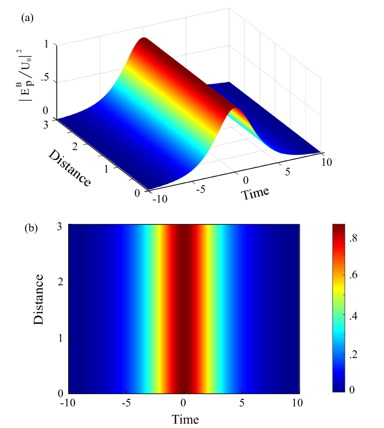
In order to investigate the evolution and the propagation for the bright polaritonic solitons, we assume the initial condition as . It is noteworthy to mention that the proposed scheme can be observed in an experiment by choosing realistic parameter. By taking , , , one can assume a stable propagation of the bright polaritonic soliton. For these specific values, we get . The spatiotemporal dynamics of the bright polaritonic solitons within the EIT transparency window, in the proposed structure as a function of distance and time is described in Fig. 3. Figure 3(a), illustrates the evolution of the probe field intensity as a function of and while Fig. 3(b) represents the corresponding 2D contour plot of the bright polaritonic solitons. It is evident from the figure that the bright polaritonic solitons can propagate through the waveguide for a long distance without encountering much distortion. The bright polaritonic soliton retains its shape and amplitude as it propagates through the system. This stable propagation is achieved as a result of the balanced dispersion with the sufficient self-focusing provided by the inherent Kerr nonlinearity within the EIT transparency window of the system.
Similar investigation can be carried out for the case of dark polaritonic solitons as well. For , we obtain the fundamental dark soliton solutions which is given by . By returning to the original variables, the dark polaritonic soliton solution is given by the relation , which can be further expressed as follows:
| (16) |
For the dark polaritonic solitons, the corresponding electric fields is given by the expression:
| (17) |
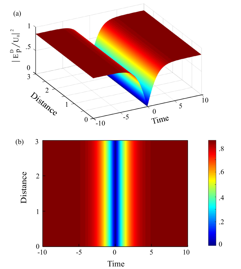
The propagation dynamics of the dark polaritonic soliton is numerically investigated by taking the initial condition is taken as . Figure 4 illustrates the spatiotemporal evolution of the dark surface polaritonic solitons in the planar plasmonic waveguide structure. The evolution of the probe field intensity as a function of and is shown in Fig. 4(a) along with the corresponding contour map in Fig 4(b). Similar to the case of the bright polaritonic solitons, the initial pulse retains its shape and amplitude for a long distance in the case of the dark polaritonic solitons as well, resulting in the stable propagation of the pulse in the proposed system. Such undistorted propagation of these polaritonic solitons can find immense applications in communication in the optical regime.
V Excitation of surface polaritonic Akhmedeiv breathers
The standard NLSE, described by Eq. 13, can assume other exact solutions which are periodic in and . The Akhmediev breather is one such solution, and it is given by the expression
| (18) |
Then, we have
| (19) |
Returning to the original variables we get
| (20) |
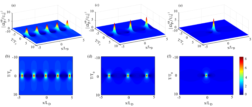
where, is the modulation parameter, is the spatial modulation frequency and is the parametric gain coefficient. is the time period of the periodic pulses. The spatiotemporal evolution of the surface polaritonic Akhmediev breathers in the planar plasmonic waveguide structure for different values of , is depicted in Fig. 5. In order to have a physical understanding of the evolution of the surface polaritonic Akhmediev Breather, we can assume the initial SPs to be a plane wave (corresponding to ) which evolves into a significant pulse shape due to the parametric gain coefficient. As a result the SP’s amplitude gets significantly amplified by a growth factor of . With further modulation of the instability, the amplified SP’s evolves into a train of periodic pulses along the time axis with a period of . Hence, the first-order surface polaritonic Akhmediev breathers can be potentially excited and propagated in this waveguide.
The dynamics of the surface polaritonic Akhmediev breather in the proposed structure depends strongly on the spatial modulation frequency. Here, for , it is evident from Fig. 5 that the spatial separation between the adjacent peak intensities increases with the increase of . By taking realistic values of the modulation parameter as (see Figs. 5(a), (b)), we can obtain a train of pulses with a time-period , and , . Figures 5 (c) and 5(d), represents the breather propagation for the modulation parameter, with , and . It is observed that the spatial width of the individual pulse decreases with increasing value of the modulation parameter while the temporal width of the pulses increases with an increase of the modulation parameter. Finally, for a limiting case of , there is a significant spatial and temporal localization of the pulse leading to an increased localization of peak intensity. This spatiotemporally localized pulse is the so-called Peregrine soliton which is depicted in Figs. 5(e) and 5(f). Hence, a stable propagation of the surface polaritonic Akhmediev Breather is possible in the structure with judicious choice of parameters. The effective localization of these surface polaritonic breathers can lead to the generation of extremely short pulses in such coupler-free planar plasmonic structure.
VI Conclusion
In conclusion, we investigate the excitation of surface polaritonic solitons and breathers in a coupler-free planar plasmonic waveguide structure comprising of a transparent layer, a metal layer and a three-level lambda-type atomic medium. In the linear regime, it is observed that the coupler-free excitation of SP resonances is possible in the proposed structure. Further, a giant Kerr nonlinearity is achieved in the system as a result of electromagnetically induced transparency in the bottom atomic layer, which can be controlled through proper modulation of the parameters of the driving laser fields. The self-phase modulation caused by the Kerr nonlinearity balances the group velocity dispersion in the system hence providing the necessary condition for the excitation of surface polaritonic solitons within the narrow transparency window of the electromagnetically induced transparency. It is observed that the system yields laterally self-trapped bright and dark surface polaritonic solitons which is tightly guided at the interface of the metal and the EIT medium. Finally, we have shown that a stable propagation and an effective localization of the surface polaritonic Akhmediev breathers can be achieved with proper choice of parameters in the proposed planar plasmonic waveguide structure. This study can be significant in the development of highly compact nano-optical and photonic devices for applications in the optical regime.
References
- (1) M. Fleischhauer, A. Imamoglu, and J.P Marangos. Electromagnetically induced transparency: Optics in coherent media. Rev. of modern physics, 77(2):633, 2005.
- (2) J.P. Marangos. Electromagnetically induced transparency. Journal of Modern Optics, 45(3):471–503, 1998.
- (3) M.D. Lukin and A. Imamoğlu. Controlling photons using electromagnetically induced transparency. Nature, 413(6853):273, 2001.
- (4) D.F. Phillips, A. Fleischhauer, A. Mair, R.L. Walsworth, and M.D. Lukin. Storage of light in atomic vapor. Phys. Rev. Lett., 86(5):783, 2001.
- (5) Y-q. Li and M. Xiao. Enhancement of nondegenerate four-wave mixing based on electromagnetically induced transparency in rubidium atoms. Opt. Lett., 21(14):1064–1066, 1996.
- (6) D.A. Braje, V. Balić, S. Goda, GY Yin, and SE Harris. Frequency mixing using electromagnetically induced transparency in cold atoms. Phys. Rev. Lett., 93(18):183601, 2004.
- (7) H Schmidt and A Imamoglu. Giant kerr nonlinearities obtained by electromagnetically induced transparency. Opt. Lett., 21(23):1936–1938, 1996.
- (8) H. Wang, X. Gu, Y.-xi Liu, A. Miranowicz, and F. Nori. Optomechanical analog of two-color electromagnetically induced transparency: Photon transmission through an optomechanical device with a two-level system. Phys. Rev. A, 90(2):023817, 2014.
- (9) A.H Safavi-Naeini, TP Mayer Alegre, J. Chan, M. Eichenfield, M. Winger, Q. Lin, J. T Hill, D. E Chang, and O. Painter. Electromagnetically induced transparency and slow light with optomechanics. Nature, 472(7341):69, 2011.
- (10) S. Zhang, D.A. Genov, Y. Wang, M. Liu, and X. Zhang. Plasmon-induced transparency in metamaterials. Phys. Rev. lett., 101(4):047401, 2008.
- (11) N. Papasimakis, V. A Fedotov, N.I. Zheludev, and S.L. Prosvirnin. Metamaterial analog of electromagnetically induced transparency. Phys. Rev. Lett., 101(25):253903, 2008.
- (12) K. Monika Devi, Amarendra K Sarma, D. R. Chowdhury, and Gagan Kumar. Plasmon induced transparency effect through alternately coupled resonators in terahertz metamaterial. Opt. Express, 25(9):10484–10493, 2017.
- (13) K. Monika Devi, M. Islam, D. R. Chowdhury, Amarendra K Sarma, and Gagan Kumar. Plasmon-induced transparency in graphene-based terahertz metamaterials. EPL, 120(2):27005, 2018.
- (14) M Mahat, Y Rostovtsev, S Karna, G N Lim, F DSouza, and and A Neogi. Plasmonically Induced Transparency in Graphene Oxide Quantum Dots with Dressed Phonon States. ACS Photonics, 5(2):614–620, 2017.
- (15) C. Du. Quantum surface plasmon resonance system based on electromagnetically induced transparency. Appl. Phys. A, 109(4):797–803, 2012.
- (16) J. Q. Shen. Electromagnetically-induced-transparency plasmonics: Quantum-interference-assisted tunable surface-plasmon-polariton resonance and excitation. Phys. Rev. A, 90(2):023814, 2014.
- (17) Stefan A. Maier. Plasmonics: fundamentals and applications. Springer Science & Business Media, 2007.
- (18) Vladimir M Shalaev and S. Kawata. Nanophotonics with surface plasmons. Elsevier, 2006.
- (19) Dmitri K Gramotnev and Sergey I Bozhevolnyi. Plasmonics beyond the diffraction limit. Nat. photonics, 4(2):83, 2010.
- (20) Jon A Schuller, Edward S Barnard, Wenshan Cai, Young Chul Jun, Justin S White, and Mark L Brongersma. Plasmonics for extreme light concentration and manipulation. Nat. Mater., 9(3):193, 2010.
- (21) Y Poudel, G N Lim, M Moazzezi, Z Hennighausen, Y Rostovtsev, F DSouza, S Kar, and A Neogi. Active control of coherent dynamics in hybrid plasmonic MoS2 monolayers with dressed phonons. arXiv preprint, arXiv:1810.02056:016617, 2018.
- (22) L Wu, H.S. Chu, W.S. Koh, and E.P. Li. Highly sensitive graphene biosensors based on surface plasmon resonance. Opt. Express, 18(14):14395–14400, 2010.
- (23) J. Zhang, L. Zhang, and W. Xu. Surface plasmon polaritons: physics and applications. J. Phys. D: Applied Physics, 45(11):113001, 2012.
- (24) K.R. Catchpole, , and A. Polman. Plasmonic solar cells. Opt. Express, 16(26):21793–21800, 2008.
- (25) V. E. Ferry, M. A. Verschuuren, Hongbo BT Li, E. Verhagen, R. J. Walters, Ruud EI Schropp, H. A. Atwater, and A. Polman. Light trapping in ultrathin plasmonic solar cells. Opt. Express, 18(102):A237–A245, 2010.
- (26) D. Ziemkiewicz, K. Słowik, and S. Zielińska-Raczyńska. Ultraslow long-living plasmons with electromagnetically induced transparency. Opt. Lett., 43(3):490–493, 2018.
- (27) C. Du, Q. Jing, and Z. Hu. Coupler-free transition from light to surface plasmon polariton. Phys. Rev.A, 91(1):013817, 2015.
- (28) Z. Bai, G. Huang, L. Liu, and S. Zhang. Giant kerr nonlinearity and low-power gigahertz solitons via plasmon-induced transparency. Sci. Rep., 5,13780, 2015.
- (29) Z. Bai and G. Huang. Plasmon dromions in a metamaterial via plasmon-induced transparency. Phys. Rev. A, 93(1):013818, 2016.
- (30) S. Asgarnezhad-Zorgabad, R. Sadighi-Bonabi, and C. Hang. Coupler-free surface polariton excitation and propagation with cold four-level atomic medium. JOSA B, 34(9):1787–1795, 2017.
- (31) S. Asgarnezhad-Zorgabad, R. Sadighi-Bonabi, and B. C Sanders. Excitation and propagation of surface polaritonic rogue waves and breathers. Phys. Rev. A, 98(1):013825, 2018.
- (32) Robert W Boyd. Nonlinear optics. Elsevier, 2003.
- (33) Philip G Drazin and Robin S Johnson. Solitons: an introduction, volume 2. Cambridge university press, 1989.
- (34) E. Feigenbaum and M. Orenstein. Plasmon-soliton. Opt. Lett., 32(6):674–676, 2007.
- (35) A. Marini, D. V Skryabin, and B. Malomed. Stable spatial plasmon solitons in a dielectric-metal-dielectric geometry with gain and loss. Opt. Express, 19(7):6616–6622, 2011.
- (36) M. Kumar, K Porsezian, P Tchofo-Dinda, Ph Grelu, T Mithun, and T Uthayakumar. Spatial modulation instability of coupled surface plasmon polaritons in a dielectric–metal–dielectric structure. JOSA B, 34(1):198–206, 2017.
- (37) K. Monika Devi, K Porsezian, and Amarendra K Sarma. Surface plasmon polariton akhmediev breather in a dielectric-metal-dielectric geometry with subwavelength thickness. Superlattices and Microstructures, 117, 392–398, 2018.
- (38) Y. Dong, D. Wang, Y. Wang, and J. Ding. Matching group velocity of bright and/or dark solitons via double-dark resonances. Phys. Lett. A, 382(30):2006–2012, 2018.
- (39) H. Wang, D. Goorskey, and M. Xiao. Enhanced kerr nonlinearity via atomic coherence in a three-level atomic system. Phys. Rev. lett., 87(7):073601, 2001.
- (40) L. V. Doai, D. X. Khoa, and N. Huy Bang. EIT enhanced self-kerr nonlinearity in the three-level lambda system under doppler broadening. Physica Scripta, 90(4):045502, 2015.
- (41) M. Bass, C. DeCusatis, J. Enoch, V. Lakshminarayanan, G. Li, C. MacDonald, V. Mahajan, Eric V. Stryland. Handbook of optics. McGraw Hill, 4, p. 849-854, 2009.
- (42) Daniel A Steck. Sodium d line data. Report, Los Alamos National Laboratory, Los Alamos, 124, 74, 2000.
- (43) Edward D Palik. Handbook of optical constants of solids, volume 3. Academic press, 1998.
- (44) G. Huang, L. Deng, and MG Payne. Dynamics of ultraslow optical solitons in a cold three-state atomic system. Phys. Rev. E, 72(1):016617, 2005.