Layer-dependent spin-orbit torques generated by the centrosymmetric transition metal dichalcogenide -MoTe2
Abstract
Single-crystal materials with sufficiently low crystal symmetry and strong spin-orbit interactions can be used to generate novel forms of spin-orbit torques on adjacent ferromagnets, such as the out-of-plane antidamping torque previously observed in WTe2/ferromagnet heterostructures. Here, we present measurements of spin-orbit torques produced by the low-symmetry material -MoTe2, which unlike WTe2 retains bulk inversion symmetry. We measure spin-orbit torques on -MoTe2/Permalloy heterostructures using spin-torque ferromagnetic resonance as a function of crystallographic alignment and MoTe2 thickness down to the monolayer limit. We observe an out-of-plane antidamping torque with a spin torque conductivity as strong as 1/3 of that of WTe2, demonstrating that the breaking of bulk inversion symmetry in the spin-generation material is not a necessary requirement for producing an out-of-plane antidamping torque. We also measure an unexpected dependence on the thickness of the -MoTe2 – the out-of-plane antidamping torque is present in MoTe2/Permalloy heterostructures when the -MoTe2 is a monolayer or trilayer thick, but goes to zero for devices with bilayer -MoTe2.
Spin-orbit torques represent one of the most promising methods for manipulating emerging magnetic memory technologies Brataas et al. (2012). When a charge current is applied to a material with large spin-orbit coupling, such as a heavy metal Miron et al. (2010, 2011); Liu et al. (2011, 2012a, 2012b); Pai et al. (2012), topological insulator Mellnik et al. (2014); Fan et al. (2014), or transition metal dichalcogenide (TMD) Zhang et al. (2016a); Shao et al. (2016); MacNeill et al. (2017a, b); Guimarães et al. (2018); Li et al. (2018); Stiehl et al. (2019), a spin current generated through mechanisms such as the spin Hall or Rashba-Edelstein effects can be used to exert a torque on an adjacent ferromagnet. Recent work from several research groups has focused on understanding how a controlled breaking of symmetry in a spin-generating material / ferromagnet heterostructure can be used to tune the direction of the observed spin-orbit torques for optimal switching of magnetic devices Baek et al. (2018); Safranski et al. (2018); Gibbons et al. (2018); Ou et al. ; Fang et al. (2011); Kurebayashi et al. (2014); Skinner et al. (2015); Ciccarelli et al. (2016); MacNeill et al. (2017a, b); Guimarães et al. (2018). For instance, the presence of magnetic order within a spin-generation layer can allow current-generated spin directions that are typically forbidden for highly-symmetric non-magnetic metals Baek et al. (2018); Safranski et al. (2018); Gibbons et al. (2018); Ou et al. . Similarly, our group has shown that by using WTe2 as the spin-source material, a TMD with a low-symmetry crystal structure, it is possible to generate an out-of-plane antidamping torque MacNeill et al. (2017a, b) – the component of torque required for the most efficient mode of switching for magnets with perpendicular magnetic anisotropy, but forbidden in higher-symmetry materials. Only one other material, SrRuO3, has been shown to generate an out-of-plane antidamping spin-orbit torque Ou et al. , arising from symmetry breaking associated with magnetic order. Many questions remain regarding the mechanism and necessary conditions for generating a strong out-of-plane antidamping torque.
In this work, we study the spin-orbit torques generated in TMD/ferromagnet heterostructures with a crystal symmetry that is distinct from WTe2 in an important way – inversion symmetry is intact in the bulk of the spin-generation material. We perform spin-torque measurements of TMD/ferromagnet heterostructures with the monoclinic phase () of MoTe2 as the spin-source material. Using spin-torque ferromagnetic resonance (ST-FMR), we measure the spin-orbit torques as a function of crystal axis alignment and TMD thickness down to the monolayer limit. We find that an out-of-plane antidamping torque is present in -MoTe2/ferromagnet heterostructures even though inversion symmetry is intact in the MoTe2 bulk. Interestingly, we find that while this out-of-plane antidamping torque is strong in both monolayer and trilayer thick MoTe2 devices, the observed torque goes to zero in bilayer-thick MoTe2.
The monoclinic ( or 1T’) phase of MoTe2 provides a unique opportunity to probe the symmetries relevant for the generation of novel spin-orbit torques, in that the individual monolayers of -MoTe2 are isostructural to WTe2 monolayers, but are stacked such that inversion symmetry is maintained in the bulk crystal. Bulk -MoTe2 has the space group P21/m, (#11), with a screw axis along the Mo chain and a mirror plane perpendicular to the screw axis (Fig. 1a) Clarke et al. (1978). Similar to WTe2, however, the surface symmetry is limited to just one mirror plane perpendicular to the Mo chain shown in Fig. 1b.
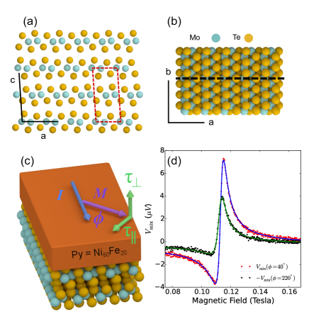
To fabricate our samples we exfoliate flakes of bulk -MoTe2 crystal (provided by HQ graphene) onto high resistivity silicon / silicon oxide wafers, where the last step of the exfoliation process is carried out under vacuum ( torr) in the load lock of our sputtering system. We then use grazing angle sputtering to deposit 6 nm of our ferromagnet, Permalloy (Py=Ni80Fe20), and subsequently cap the films with 2 nm of Al that is oxidized upon exposure to air. The equilibrium direction of the Py magnetic moment is within the sample plane. Flakes are identified for patterning by optical and atomic force microscopy (AFM); we select regions of flakes that are clean (no tape residue) and atomically flat (300 pm roughness) with no monolayer steps over the entire region from which devices will be fabricated. The thicknesses of the -MoTe2 flakes can be accurately determined by AFM (with a layer step-height of 0.7 nm). Samples are then patterned into device structures using electron beam lithography and ion mill etching. Electrical contact is made using 5 nm Ti/75 nm Pt electrodes. The data presented in the main text of this work are all taken at room temperature. We have confirmed that all our devices (down to the monolayer limit) are in the -MoTe2 phase at room temperature by polarized Raman spectroscopy (see Appendix). We have also used polarized Raman spectroscopy to determine the crystallographic orientation of each device with respect to the applied current direction Beams et al. (2016); Chen et al. (2016); Zhou et al. (2017); Zhang et al. (2016b); Wang et al. (2017); Cho et al. (2015); He et al. (2018).
For the ST-FMR measurements Liu et al. (2011); Mellnik et al. (2014); MacNeill et al. (2017a), we use a ground-signal-ground type device structure, in which we apply a GHz frequency current to the MoTe2/Py bar through the capacitive branch of a bias tee. We set the angle of the applied magnetic field with respect to the current direction, , and sweep the magnitude of that field to tune the ferromagnet through its resonance condition while measuring the resultant DC mixing voltage at the inductive end of the bias tee. The mixing voltage, , as a function of field magnitude can be fit accurately as the sum of symmetric and antisymmetric Lorentzians. The amplitudes of those Lorentzians are related to the in-plane () and out-of-plane () torques on the ferromagnet, respectively, by Liu et al. (2011); Mellnik et al. (2014); MacNeill et al. (2017a):
| (1) |
| (2) |
where is the device resistance, is due to the anisotropic magnetoresistance in the Py, is the out-of-plane demagnetization field, is the resonance field, is the microwave current in the bilayer, is the Gilbert damping coefficient and is the gyromagnetic ratio. Figure 1d shows at two applied field angles, and , for one of our devices (Device 1, containing one monolayer of MoTe2) where the applied current in the device is perpendicular to the MoTe2 mirror plane and the trace has been multiplied by for comparison. Fits to the data using a sum of symmetric and antisymmetric Lorentzians show good agreement.
In high symmetry materials such as Pt, the generated spin-orbit torques are limited by symmetry to consist of an out-of-plane field-like torque, , and an in-plane antidamping torque, , which both have a dependence on the magnetization direction Garello et al. (2013). That the data in Fig. 1d are not identical up to a minus sign for the two applied field angles indicates that torques in the -MoTe2/Py system do not preserve two-fold symmetry, an out-of-plane antidamping torque, , may be present. Note that we define the applied current as always being in the direction (Fig. 1c).
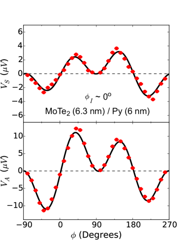
To determine the components of current-induced torque, we analyze the extracted fit parameters and as a function of applied field angle. Representative data for Device 1 are shown in Fig. 2a and b. If only the torques and are present, and will be , where the arises from due to the anisotropic magnetoresistance of the Py. However, the angular dependence of (Fig. 2b) cannot be described with this simple overall angular dependence . To extract the other out-of-plane torques present in the system, we fit the angular dependence of as:
| (3) |
The fit parameter corresponds to torques . The fit parameter corresponds to torques – the torque with a Dresselhaus-like symmetry observed in TaTe2 and WTe2 that likely arises from the in-plane resistance anisotropy of the low-symmetry TMD Stiehl et al. (2019). For Device 1, we find a ratio indicating a sizable out-of-plane antidamping torque, whereas is zero to within experimental uncertainty.

We may similarly fit to test for additional in-plane torques:
| (4) |
where corresponds to torques , and gives torques . In Device 1, and are zero within experimental uncertainty. However, other samples show non-zero values for and as discussed below.
When a spin-generation system has a single mirror symmetry and the current is applied perpendicular to this mirror plane (as is the case for the MoTe2/Py interface of Device 1 in Fig. 2a,b) a net torque generated by an out-of-plane spin is allowed by symmetry (a torque or ). However, if the current instead flows along a mirror plane, such a torque is forbidden by symmetry. Figure 2c and d shows and for a MoTe2/Py device in which current is applied along the MoTe2 mirror plane (Device 2). Consistent with this symmetry requirement, fits of using Eq. 3 yield values of that are zero within experimental uncertainty. We note the presence of a small, but nonzero, value of as determined by fits of using Eq. 4, , which is discussed below and in Appendix F.
The torque conductivity, defined as the angular momentum absorbed by the magnet per second per unit interface area per unit applied electric field, provides an absolute measure of the torques produced in a spin source/ferromagnet heterostructure nominally independent of geometric factors. For a torque (where = , , , , or ) we calculate the corresponding torque conductivity via
| (5) |
where is the saturation magnetization, is the electric field, and are the length and width of the MoTe2/Py bilayer, nm is the thickness of the Py, and is the device impedance. The factor is the total angular momentum of the magnet, and converts the normalized torque into units of angular momentum per second. Further details of the ST-FMR analysis can be found in Appendix A.
We have determined the torque conductivities for 20 MoTe2()/Py(6 nm) devices, all with distinct thicknesses of MoTe2, , and angles between the current direction and the MoTe2 mirror plane. Details of each device can be found in Table 1 of the Appendix. We define as the angle between the current and the vector normal to the MoTe2 mirror plane (typically called the b-axis in the phase), such that is perpendicular to the mirror plane and is parallel. Figure 3a shows as a function of for 17 of our devices (we have excluded our bilayer thick MoTe2 devices for now, which will be discussed later). Consistent with the symmetry requirements on the torques, is largest when current is applied perpendicular to the MoTe2 mirror plane and is progressively reduced as more of the applied current flows along the mirror plane. Note that in Fig. 3a we have plotted . This is because the sign of is not solely determined by but also the canting of the molybdenum dimerization at the MoTe2/Py interface, which we do not control and cannot determine by polarized Raman spectroscopy (to visualize this difference, consider a two-fold rotation about the MoTe2 c-axis for a monolayer).
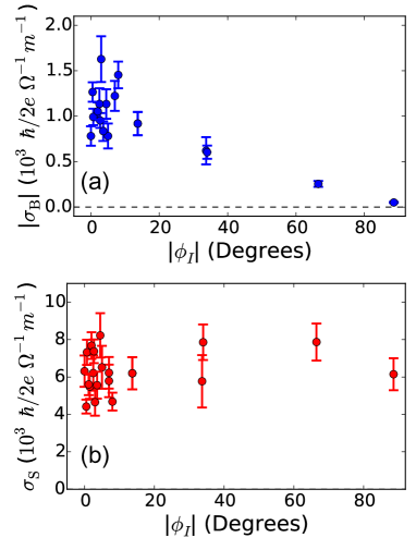
In contrast to the strong dependence on for , the torque conductivity for the conventional component of in-plane antidamping spin Hall torque, , shows no significant dependence (Fig. 3b). This is similar to the dependence on observed in our WTe2/Py heterostructuresMacNeill et al. (2017a, b). We note, however, that the relative insensitivity of to the in-plane current direction observed in -MoTe2 and WTe2 is not required by symmetry, and in general the magnitudes of the in-plane spins generated in response to a current along the a or b-axes are allowed to differZhu et al. (2018). We obtain an average value of for our MoTe2/Py devices of , smaller than the average value observed in our WTe2/Py heterostructures, MacNeill et al. (2017a, b), and larger than the observed in our NbSe2/Py heterostructures Guimarães et al. (2018).
To help analyze the mechanism that drives the spin-orbit torques in our MoTe2/Py heterostructures, it is helpful to study the torques as a function of MoTe2 thickness, holding the crystal alignment fixed. In Appendix D, we discuss the observed thickness dependence for , and show that this torque contribution is dominated by the Oersted field. Figure 4a shows the thickness dependence for and for devices with current aligned perpendicular to the MoTe2 mirror plane, where and usually less than 10∘. Both torques are largely independent of MoTe2 thickness, with the notable exception of bilayer MoTe2 devices, implying an interfacial origin for these torque components. This is in qualitative similarity to the TMD thickness dependence previously observed in WTe2. The striking exception in the thickness dependence is from our devices in which the MoTe2 is just a bilayer (1.4 nm) thick (3 different samples). In these devices, no out-of-plane antidamping torque is observed within our experimental uncertainty. Excluding the bilayer devices, we find an average value for . It is interesting that while the magnitude of in MoTe2 is similar to that observed in our WTe2 devices, the value of is approximately 1/3 that of WTe2 MacNeill et al. (2017a, b).
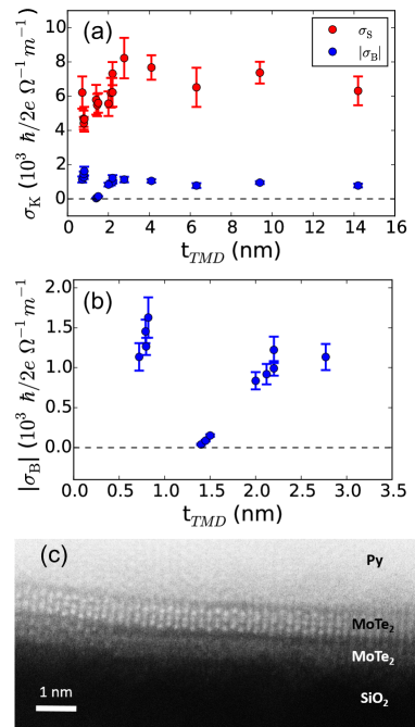
Figure 4b shows in more detail the measured out-of-plane antidamping torque conductivity in MoTe2/Py heterostructures in monolayer steps from a single MoTe2 layer to quadlayer MoTe2, all with current perpendicular to the MoTe2 mirror plane. The contrast is striking between the large torques in the monolayer, trilayer and quadlayer MoTe2 devices, and the nearly-zero torque in the three bilayer samples. In our previous work on WTe2/Py devices, bilayer WTe2 (two samples) also showed a decrease in , although in that case for the bilayer devices was that of the monolayer and trilayer devices rather than zero (see Fig. 5 of Ref. MacNeill et al. (2017b)). The origin of these reductions is unknown. Only the out-of-plane antidamping torque is reduced, not or . In WTe2, non-symmorphic crystal symmetries (the b-c glide plane and c-axis screw) require that the spin responsible for generating must have opposite signs in adjacent layers MacNeill et al. (2017b). While -MoTe2 does not possess the same non-symmorphic symmetries, there is an effective in-plane polar vector at the -MoTe2/Py interface that changes sign for adjacent -MoTe2 layers Shi and Song (2019), which could lead to oppositely-directed current-induced out-of-plane spins in adjacent layers. Such a layer-dependent sign for the out-of-plane spin might lead to a partial cancellation of contributions from adjacent layers, and may have some bearing on this layer-dependent effect. However, this mechanism alone is difficult to reconcile with our observations that a strong layer dependence is present only in the bilayer MoTe2, and that the lower layer in our bilayer devices is also likely partially oxidized (see below).
The in-plane field-like torque, , has the same symmetry constraints as and is symmetry allowed in our MoTe2/Py devices when the current is applied perpendicular to the MoTe2 mirror plane. Interestingly, we observe significant values of only in devices with sufficiently thick MoTe2, above about 3 nm. Details can be found in Appendix F and H. In all such devices the ratio of is always negative, even though the signs of and vary from sample to sample. In addition, we find that and scale similarly with the sample temperature. These observations suggest that the two torque components are correlated. However, we also find that and have distinct dependencies on the MoTe2 thickness, in tension with the idea that the two torques are generated through the same mechanism. Surprisingly, we also find a significant, though reduced, value of in samples where current is flowed predominately along the MoTe2 mirror plane (Fig. 2c) – the condition under which the torque is symmetry forbidden. This suggests the possibility of two distinct mechanisms contributing to the generation of : one which is correlated with and the MoTe2 crystal structure, and the other independent of the nominal MoTe2 crystal structure and possibly due to strain induced by the fabrication procedure Guimarães et al. (2018); Lee et al. (2017). We note that the observation of non-zero values of both and in the same sample is in contrast to previous measurements on other TMDs. In WTe2 we did not observe any significant value of even though a large was present (see Fig. 6 of Ref. MacNeill et al. (2017b)). For (presumably) strained NbSe2/Py devices the situation was exactly the opposite. There we observed a large value of , but no , though with no clear dependence on the TMD thickness.
To better understand the microscopic structure of the MoTe2/Py samples, we have performed cross-sectional high-angle annular dark-field scanning transmission electron microscopy (HAADF-STEM) imaging on a bilayer -MoTe2/Py device (Fig. 4c) as initially identified by AFM. Both -MoTe2 layers are clearly visible. However, the layer adjacent to the Si/SiO2 substrate shows increased localized disorder in some regions, which we attribute to partial oxidation. Note that this partially oxidized layer remains crystallographically oriented in the unoxidized regions, while the top layer appears pristine. Oxidation just of the lower MoTe2 layer is consistent with our sample fabrication process – the layer of MoTe2 adjacent to the substrate is exposed to air before being placed on the substrate for exfoliation, while the other layers are protected from air exposure throughout the fabrication process. The existence of partial oxidation of the lowest MoTe2 layer is also consistent with the signal strengths from our polarized Raman spectroscopy measurements for monolayer and bilayer thick -MoTe2/Py devices: the bilayer thick samples show a strong signal, whereas the monolayer devices show a significantly weaker signal, but with no evidence of crystallographic twinning in either data set (see Appendix).
In summary, we have studied the current-induced spin-orbit torques in -MoTe2/Py heterostructures at room temperature. We have observed an out-of-plane antidamping torque, , qualitatively similar to the observed in WTe2/Py heterostructures. This torque is consistent with the symmetries of the MoTe2 surface – at the interface of MoTe2 and Py the structural symmetries are limited to a single mirror plane, and consistent with that symmetry, is observed only when a component of the current is applied perpendicular to that mirror plane. This demonstrates that breaking of inversion symmetry in the bulk of the spin-generation layer is not a necessary requirement for . The magnitude of the observed torque conductivity is 1/3 that observed in similar devices that use WTe2 as the spin source layer. In both materials is largely independent of the TMD thickness. The torque conductivity for the standard antidamping torque, , is also independent of thickness indicating that both torques are likely generated by an interfacial mechanism. The notable exception in the thickness dependence of is for bilayer-thick MoTe2 devices, for which is zero to within measurement uncertainty. Bilayer WTe2 devices also have a greatly-reduced out-of-plane antidamping torque compared to monolayer or trilayer devices, but the origin of this effect is unknown.
Acknowledgements: GMS acknowledges useful conversations with Dr. David MacNeill. The primary support for this project came from the US Department of Energy (DE-SC0017671). Electron microscopy was performed with support from the NSF through PARADIM as part of the Materials for Innovation Platform Program. Sample fabrication was performed in the shared facilities of the Cornell Center for Materials Research (NSF DMR-1719875) and at the Cornell Nanoscale Science & Technology Facility, part of the National Nanotechnology Coordinated Infrastructure, which is supported by the NSF (NNCI-1542081). The FEI Titan Themis 300 was acquired through Grant NSF-MRI-1429155, with additional support from Cornell University, the Weill Institute, and the Kavli Institute at Cornell.
| Device | (nm) | (m) | (degrees) | |||
| Number | 0.3 nm | 0.2 m | ||||
| 1 | 0.7 | -6.2(1) | -1.1(2) | 0.026(5) | 3 | |
| 2 | 5.6 | -6.1(9) | 0.051(7) | -0.39(6) | 89 | |
| 3 | 6.3 | -7(1) | -0.8(1) | 0.8(1) | 5 | |
| 4 | 1.4 | -5.8(9) | -0.04(1) | -0.22(5) | 7 | |
| 5 | 14.2 | -6.3(8) | -0.8(1) | 0.7(1) | 0 | |
| 6 | 2.1 | -6.2(9) | 0.9(1) | -0.13(2) | 14 | |
| 7 | 2.2 | -7.3(7) | -0.99(9) | 0.032(5) | 1 | |
| 8 | 2.8 | -8(1) | -1.1(2) | 0.28(4) | 5 | |
| 9 | 4.1 | -7.7(7) | 1.1(1) | -0.78(7) | 2 | |
| 10 | 9.4 | -7.4(6) | 0.95(8) | -1.0(1) | 3 | |
| 11 | 0.8 | -4.4(4) | -1.3(1) | 0.14(1) | 1 | |
| 12 | 1.5 | -5.5(7) | -0.09(1) | 0.25(3) | 2 | |
| 13 | 1.5 | -5.6(6) | -0.15(2) | 0.23(2) | 1 | |
| 14 | 2.0 | -5.6(7) | -0.8(1) | 0.21(3) | 4 | |
| 15 | 2.2 | -6.2(8) | 1.2(2) | 0.18(2) | 7 | |
| 16 | 0.8 | -4.7(5) | -1.4(1) | 0.06(1) | 8 | |
| 17 | 0.8 | -4.7(7) | 1.6(3) | 0.08(1) | 3 | |
| 18 | 2.2 | -5(1) | 0.6(2) | -0.17(4) | 34 | |
| 19 | 2.3 | -8(1) | -0.60(7) | -0.41(5) | 34 | |
| 20 | 9.4 | -8(1) | -0.26(3) | -0.55(7) | 67 |
Appendix A Calibrated ST-FMR measurements
To make a quantitative measurement of the magnitude of the torques using Eqs. 1 and 2 we must first determine values for , , and . The Gilbert damping is estimated from the frequency dependence of the linewidth via , where is the inhomogeneous broadening. is determined by measurements of the device resistance as a function applied in-plane magnetic field angle (with a field magnitude of 0.1 T). The RF current is determined by calibrating the reflection coefficients of our devices () and the transmission coefficient of our RF circuit () through vector network analyzer measurements. These calibrations allow calculation of the RF current flowing in the device as a function of applied microwave power and frequency:
| (6) |
where is the power sourced by the microwave generator and . The frequency dependent device impedance, , is given by .
In order to determine a torque conductivity (Eq. 5), we must also obtain a value of for the Py. As is influenced by the material on which the Py grows (here, MoTe2), and as mm-scale -MoTe2/Permalloy heterostructures are unavailable, we are unable to measure directly via magnetometry. Instead we approximate , which we have found to be accurate in other Py heterostructure systems. We estimate an average value of T as extracted from the ST-FMR measurements.
Appendix B Devices Parameters
Table 1 shows a comparison of device parameters and torque conductivities for all samples presented in this work.
Appendix C Determination of Crystal Orientation
Crystals of -MoTe2 exfoliate in the a-b plane and are generally elongated in the Mo-chain direction, with sharp and cleanly cleaved edges running parallel to that direction. This is very similar to WTe2, and can be used as a first-order approximation of the in-plane crystal axis during device fabrication. We have also verified the crystal orientation more precisely for each of our devices using Raman spectroscopy.
C.1 Raman Spectroscopy
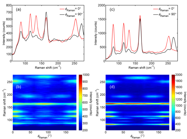
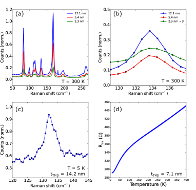
The Raman spectra of MoTe2 has been well characterized in all three crystal phases Beams et al. (2016); Chen et al. (2016); Zhou et al. (2017); Zhang et al. (2016b); Wang et al. (2017); Cho et al. (2015); He et al. (2018). We performed Raman measurements with a confocal Raman microscope using a linearly polarized 488 nm excitation and a parallel polarizer placed in front of the spectrometer. The sample is aligned to the linear polarization direction (along the length of the device) and spectra are taken as the sample is rotated in steps of 10o. The maximum of the cm-1 and cm-1 peaks correspond to the MoTe2 b-axis. Figure 5 shows polarized Raman spectra for two MoTe2/Py devices in which the MoTe2 is (a,b) a monolayer and (c,d) a bilayer thick. The symmetries of the observed peaks are consistent with previous measurements Beams et al. (2016); Chen et al. (2016). No evidence of crystallographic twinning is observed in the polarized Raman spectra.
C.2 Magnetic Easy Axis
In WTe2/Py bilayers, we observed previously that the WTe2 induced a strong in-plane magnetic easy axis that corresponded with the b-axis of the crystal, regardless of the applied current direction MacNeill et al. (2017a, b). This correlation provided an efficient means for extracting the angle between the WTe2 crystal axes and the current direction through electrical measurements alone. However, we find that MoTe2 does not induce any significant magnetic easy-axis within the Py, so this method cannot be used to characterize the crystal alignment of MoTe2. TaTe2 generates a magnetic easy axis with strength intermediate between WTe2 and MoTe2 Stiehl et al. (2019). This variation suggests different degrees of coupling between the TMDs and Permalloy.
Appendix D Out-Of-Plane Field-Like Torque and Oersted Torque
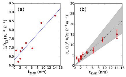
We extract the individual resistivities of the MoTe2 and Py layers using the two-point resistances of our devices for which the current is aligned perpendicular to the MoTe2 mirror plane (i.e., ) within 15∘ and usually within 10∘, where we have used only devices in which the Py thin-film and Al capping layers where grown in the same sputtering deposition batch in order to minimize effects from small variations in the Py and Al thicknesses. We plot the inverse of the sheet resistance as a function of (Fig. 6a), and using the relation:
| (7) |
extract the resistivities ( ) and ( ). The value obtained for is similar to that seen in our WTe2/Py devices when the Py is deposited using glancing-angle sputtering.
Figure 6b shows as a function of (red circles) for devices in which current is aligned perpendicular to the MoTe2 mirror plane. A strong thickness dependence of the torques is observed. In many material systems this component of torque, (for current in the direction), is dominated by the Oersted torque – that is, the magnetic field generated from a simple current-carrying wire. For instance, we have previously shown that this is the case in the WTe2/Py and NbSe2/Py systems. We can model the torque conductivity generated by the Oersted torque as:
| (8) |
where is the charge conductivity of the MoTe2. The dashed line in Fig. 6b shows the predicted Oersted torque using the extracted value of and the shaded region about the dashed line gives the uncertainty in the predicted torque as given by the spread in . All devices with the possible exception of our monolayer device are well described by the predicted Oersted torque. Deviation from the predicted Oersted torque in our monolayer device may suggest a non-uniform current distribution in the Py film, as cross-sectional HAADF STEM imaging of one of our -MoTe2 devices suggests that partial oxidation of the monolayer may play a role in an increased resistivity of that layer, and could affect the growth of the Py on top of such a layer (see Fig. 4c and associated discussion).
Appendix E Dresselhaus-like Torques
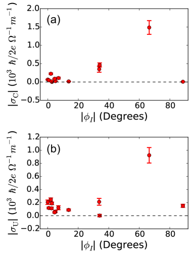
Figure 7 shows the torque conductivities for the torque components , and as a function of applied current direction, . (Recall that corresponds to current directed perpendicular to the MoTe2 mirror plane.) We refer to the torques and as Dresselhaus-like Stiehl et al. (2019). Symmetry requires that the Dresselhaus-like torques be zero when the current is either along or perpendicular to a mirror plane (e.g. or , the situations for the majority of the samples studied in this work, including all the samples shown in Fig. 4). Consistent with this requirement, in Fig. 7 both and are zero when or , and can be nonzero at intermediary angles. At present, we do not have enough devices at intermediary values of to accurately gauge the magnitude of these effects. However, these torque components should arise naturally in MoTe2/ferromagnet heterostructures because MoTe2 has an in-plane resistivity anisotropy Hughes and Friend (1978), and this will cause spatially non-uniform current flows with non-zero transverse components whenever the voltage is applied at an angle tilted away from a symmetry axis Stiehl et al. (2019).
Appendix F In-plane Field-like Torque
The symmetry requirements for the in-plane field-like torque component, are identical to that of . That is, is allowed by symmetry if there is a component of current perpendicular to the single mirror plane. In some but not all of our MoTe2/Py devices we observe a small but nonzero value of . Figure 8 shows and for one such device (Device 3, with 6.3 nm of MoTe2) for which current is applied perpendicular to the mirror plane. Fitting and with Eqs. 3 and 4 we can extract a ratio of the torques and . We observe significant values of only in devices with sufficiently thick MoTe2, above about 3 nm (Fig. 9). The average value of for samples with the MoTe2 thickness greater than 3 nm and is . In all such devices with the current perpendicular to the mirror plane the ratio of is always negative, even though the signs of and vary from sample to sample (see Fig. 9a). This, together with a similar dependence on sample temperature for and as discussed in Appendix H, suggests that these two torque components are correlated. We note, however, that and exhibit very different thickness dependencies, with showing a dependence on thickness typically associated with bulk spin-orbit torque generation, whereas is interfacial in nature.
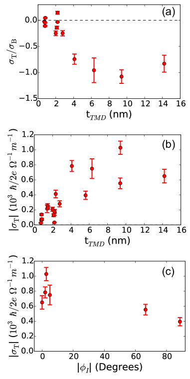
Figure 9c shows as a function of for devices with TMD thickness above 3 nm. shows a clear decrease in magnitude as the direction of the current is increasingly aligned along the MoTe2 mirror plane. However, near there remains a significantly non-zero value of inconsistent with a symmetry analysis of the nominal MoTe2/Py structure. This is reminiscent of the observed in NbSe2/Py devices Guimarães et al. (2018), in which we presumed a uniaxial strain induced by the fabrication procedure reduced the nominally high symmetry NbSe2 structure in such a way that this torque could be generated Lee et al. (2017). Note that for (presumably) strained NbSe2/Py devices we observed a large value of , but no .
Together, these observations suggest that there may be two mechanisms that contribution to in -MoTe2: one that is correlated with and dependent on the MoTe2 crystal structure, and another that is generated by a symmetry breaking associated with the strain induced during the fabrication procedure.
Appendix G Determining the Crystal Phase in the Few-Layer Limit
In bulk crystals, MoTe2 undergoes a hysteretic transition from the phase to the phase when cooled below approximately 250 K Clarke et al. (1978), with a temperature hysteresis of about 20 K. The orthorhombic () phase is obtained by a shift in the stacking of the van der Waals layers in -MoTe2. This phase is isostructural to WTe2. Both pressure Qi et al. (2016); Heikes et al. (2018) and impurity doping Rhodes et al. (2017); Oliver et al. (2017); Kim et al. (2017) have been shown to influence the transition temperature. While the majority of published studies on -MoTe2 have focused on bulk crystals Clarke et al. (1978); Tamai et al. (2016); Jiang et al. (2017); Deng et al. (2016); Huang et al. (2016); Zhang et al. (2016b); Chen et al. (2016), a handful of reports have studied the phase transition in thin films He et al. (2018); Beams et al. (2016); Chen et al. (2016); Zhou et al. (2017); Zhong et al. (2018). Recent work has suggested there may be a thickness dependence to the transition in the few-layer limit He et al. (2018); Zhong et al. (2018).
The and phase can be distinguished experimentally through polarized Raman spectroscopy by the presence in the phase of one additional peak at cm-1 and a peak splitting in the cm-1 mode Zhang et al. (2016b); Chen et al. (2016). To verify the MoTe2 crystal phase of our devices, we performed Raman spectroscopy measurements of our MoTe2/Py films using 532 nm and 633 nm excitations at room temperature and at 5 K (Fig. 10a-c). We see no evidence of the 133 cm-1 peak splitting at room temperature for samples with MoTe2 thicknesses from 2.3 nm to 12.1 nm (Fig. 10b), indicating that at room temperature our films are in the phase as expected. The 133 cm-1 peak splitting in the phase is approximately 5 cm-1 wide, and so should be resolved by these measurements. The Raman measurements at 5 K also do not show a splitting in the 133 cm-1 peak (Fig. 10c). Furthermore, measurements of the four-point resistance of a MoTe2/Py device as a function of temperature (Fig. 10d) do not show the hysteretic resistivity feature associated with the transition in bulk samples. These data therefore suggest that our thin films are stabilized in the phase, perhaps due to the deposition of the Py, with no transition to the phase in the measured temperature range.
Appendix H Temperature Dependent Measurements of Spin-Orbit Torque
One of our original motivations for studying spin-orbit torques generated by MoTe2 was to try to observe changes in the torques as the MoTe2 underwent a phase transition from the to the phase as a function of decreasing temperature. As noted in the previous section, it turns out that our device structure stabilizes the phase so that we did not observe any transition to the phase. Consistent with the lack of a phase transition in the Raman and four-point resistivity data, measurements of the spin-orbit torques as a function of temperature also reveal a smooth evolution, with no indication of an abrupt transition.
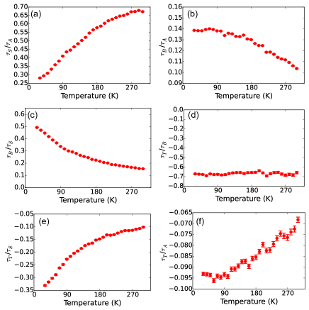
We performed temperature-dependent ST-FMR measurements for one of our MoTe2/Py devices ( nm, length 4 m and width 3 m), where current is applied perpendicular to the MoTe2 mirror plane (). Figure 11 shows the ratios of the measured torques as a function of temperature, where the torque magnitudes are extracted from the angular dependence of the applied field direction for and , as discussed in the main text. The reason why we plot torque ratios rather than individual values is that it is difficult to calibrate accurately within our cryostat the exact value of the microwave current within the sample. We observe a smooth increase in the Oersted torque with decreasing temperature, reflected in a decrease in the ratio . This is consistent with the decrease in resistivity of MoTe2 as a function of decreasing temperature, but with no indication of a phase transition to the phase. The out-of-plane antidamping component increases as temperature decreases while the corresponding in-plane antidamping component decreases, meaning that the total effective tilt angle of the generated antidamping torque is increasingly pulled out of plane with decreasing temperature. The ratio of is constant, indicating that the two torques have the same dependence on temperature. This is additional evidence for the conjecture that these two torque components may arise from related microscopic mechanisms (see discussion in Appendix F).
References
- Brataas et al. (2012) A. Brataas, A. D. Kent, and H. Ohno, Nature Materials 11, 372 (2012).
- Miron et al. (2010) I. M. Miron, G. Gaudin, S. Auffret, B. Rodmacq, A. Schuhl, S. Pizzini, J. Vogel, and P. Gambardella, Nature materials 9, 230 (2010).
- Miron et al. (2011) I. M. Miron, K. Garello, G. Gaudin, P.-J. Zermatten, M. V. Costache, S. Auffret, S. Bandiera, B. Rodmacq, A. Schuhl, and P. Gambardella, Nature 476, 189 (2011).
- Liu et al. (2011) L. Liu, T. Moriyama, D. C. Ralph, and R. A. Buhrman, Physical Review Letters 106, 036601 (2011).
- Liu et al. (2012a) L. Liu, O. J. Lee, T. J. Gudmundsen, D. C. Ralph, and R. A. Buhrman, Phys. Rev. Lett. 109, 096602 (2012a).
- Liu et al. (2012b) L. Liu, C.-F. Pai, Y. Li, H. W. Tseng, D. C. Ralph, and R. A. Buhrman, Science 336, 555 (2012b).
- Pai et al. (2012) C. F. Pai, L. Liu, Y. Li, H. W. Tseng, D. C. Ralph, and R. A. Buhrman, Applied Physics Letters 101, 122404 (2012).
- Mellnik et al. (2014) A. R. Mellnik, J. S. Lee, A. Richardella, J. L. Grab, P. J. Mintun, M. H. Fischer, A. Vaezi, A. Manchon, E.-A. Kim, N. Samarth, and D. C. Ralph, Nature 511, 449 (2014).
- Fan et al. (2014) Y. Fan, P. Upadhyaya, X. Kou, M. Lang, S. Takei, Z. Wang, J. Tang, L. He, L.-T. Chang, M. Montazeri, G. Yu, W. Jiang, T. Nie, R. N. Schwartz, Y. Tserkovnyak, and K. L. Wang, Nature Materials 13, 699 (2014).
- Zhang et al. (2016a) W. Zhang, J. Sklenar, B. Hsu, W. Jiang, M. B. Jungfleisch, J. Xiao, F. Y. Fradin, Y. Liu, J. E. Pearson, J. B. Ketterson, Z. Yang, and A. Hoffmann, APL Materials 4, 032302 (2016a).
- Shao et al. (2016) Q. Shao, G. Yu, Y. W. Lan, Y. Shi, M. Y. Li, C. Zheng, X. Zhu, L. J. Li, P. K. Amiri, and K. L. Wang, Nano Letters 16, 7514 (2016).
- MacNeill et al. (2017a) D. MacNeill, G. M. Stiehl, M. H. D. Guimarães, R. A. Buhrman, J. Park, and D. C. Ralph, Nature Physics 13, 300 (2017a).
- MacNeill et al. (2017b) D. MacNeill, G. M. Stiehl, M. H. D. Guimarães, N. D. Reynolds, R. A. Buhrman, and D. C. Ralph, Physical Review B 96, 054450 (2017b).
- Guimarães et al. (2018) M. H. D. Guimarães, G. M. Stiehl, D. MacNeill, N. D. Reynolds, and D. C. Ralph, Nano Lett. 18, 1311 (2018).
- Li et al. (2018) P. Li, W. Wu, Y. Wen, C. Zhang, J. Zhang, S. Zhang, Z. Yu, S. A. Yang, A. Manchon, and X.-X. Zhang, Nature Communications 9, 3990 (2018).
- Stiehl et al. (2019) G. M. Stiehl, D. MacNeill, N. Sivadas, I. El Baggari, M. H. D. Guimarães, N. D. Reynolds, L. F. Kourkoutis, C. Fennie, R. A. Buhrman, and D. C. Ralph, ACS Nano 13, 2599 (2019).
- Baek et al. (2018) S.-H. C. Baek, V. P. Amin, Y.-W. Oh, G. Go, S.-J. Lee, G.-H. Lee, K.-J. Kim, M. D. Stiles, B.-G. Park, and K.-J. Lee, Nature Materials 17, 509 (2018).
- Safranski et al. (2018) C. Safranski, E. A. Montoya, and I. N. Krivorotov, Nature Nanotechnology (2018).
- Gibbons et al. (2018) J. D. Gibbons, D. MacNeill, R. A. Buhrman, and D. C. Ralph, Phys. Rev. Applied 9, 064033 (2018).
- (20) Y. Ou, Z. Wang, C. S. Chang, H. P. Nair, H. Paik, N. Reynolds, D. C. Ralph, D. A. Muller, D. G. Schlom, and R. A. Buhrman, ArXiv:1810.11136 (2018).
- Fang et al. (2011) D. Fang, H. Kurebayashi, J. Wunderlich, K. Výborný, L. P. Zârbo, R. P. Campion, A. Casiraghi, B. L. Gallagher, T. Jungwirth, and A. J. Ferguson, Nature Nanotechnology 6, 413 (2011).
- Kurebayashi et al. (2014) H. Kurebayashi, J. Sinova, D. Fang, A. C. Irvine, T. D. Skinner, J. Wunderlich, V. Novák, R. P. Campion, B. L. Gallagher, E. K. Vehstedt, L. P. Zârbo, K. Výborný, A. J. Ferguson, and T. Jungwirth, Nature Nanotechnology 9, 211 (2014).
- Skinner et al. (2015) T. D. Skinner, K. Olejník, L. K. Cunningham, H. Kurebayashi, R. P. Campion, B. L. Gallagher, T. Jungwirth, and A. J. Ferguson, Nature Communications 6, 6730 (2015).
- Ciccarelli et al. (2016) C. Ciccarelli, L. Anderson, V. Tshitoyan, A. J. Ferguson, F. Gerhard, C. Gould, L. W. Molenkamp, J. Gayles, J. Železný, L. Šmejkal, Z. Yuan, J. Sinova, F. Freimuth, and T. Jungwirth, Nature Physics 12, 855 (2016).
- Clarke et al. (1978) R. Clarke, E. Marseglia, and H. P. Hughes, Philosophical Magazine B 38, 121 (1978).
- Beams et al. (2016) R. Beams, L. G. Cançado, S. Krylyuk, I. Kalish, B. Kalanyan, A. K. Singh, K. Choudhary, A. Bruma, P. M. Vora, F. Tavazza, A. V. Davydov, and S. J. Stranick, ACS Nano 10, 9626 (2016).
- Chen et al. (2016) S.-Y. Chen, T. Goldstein, D. Venkataraman, A. Ramasubramaniam, and J. Yan, Nano Letters 16, 5852 (2016).
- Zhou et al. (2017) L. Zhou, S. Huang, Y. Tatsumi, L. Wu, H. Guo, Y.-Q. Bie, K. Ueno, T. Yang, Y. Zhu, J. Kong, R. Saito, and M. Dresselhaus, Journal of the American Chemical Society 139, 8396 (2017).
- Zhang et al. (2016b) K. Zhang, C. Bao, Q. Gu, X. Ren, H. Zhang, K. Deng, Y. Wu, Y. Li, J. Feng, and S. Zhou, Nature Communications 7, 13552 (2016b).
- Wang et al. (2017) Y. Wang, J. Xiao, H. Zhu, Y. Li, Y. Alsaid, K. Yan Fong, Y. Zhou, S. Wang, W. Shi, Y. Wang, A. Zettl, E. Reed, and X. Zhang, Nature 550 (2017).
- Cho et al. (2015) S. Cho, S. Kim, J. H. Kim, J. Zhao, J. Seok, D. H. Keum, J. Baik, D.-H. Choe, K. J. Chang, K. Suenaga, S. W. Kim, Y. H. Lee, and H. Yang, Science 349, 625 (2015).
- He et al. (2018) R. He, S. Zhong, H. H. Kim, G. Ye, Z. Ye, L. Winford, D. McHaffie, I. Rilak, F. Chen, X. Luo, Y. Sun, and A. W. Tsen, Phys. Rev. B 97, 041410(R) (2018).
- Garello et al. (2013) K. Garello, I. M. Miron, C. O. Avci, F. Freimuth, Y. Mokrousov, S. Blügel, S. Auffret, O. Boulle, G. Gaudin, and P. Gambardella, Nature Nanotechnology 8, 587 (2013).
- Zhu et al. (2018) L. J. Zhu, D. C. Ralph, and R. A. Buhrman, Phys. Rev. B 98, 134406 (2018).
- Shi and Song (2019) L.-K. Shi and J. C. W. Song, Phys. Rev. B 99, 035403 (2019).
- Lee et al. (2017) J. Lee, Z. Wang, H. Xie, K. F. Mak, and J. Shan, Nature Materials 16, 887 (2017).
- Hughes and Friend (1978) H. P. Hughes and R. H. Friend, Journal of Physics C: Solid State Physics 11, L103 (1978).
- Qi et al. (2016) Y. Qi, P. G. Naumov, M. N. Ali, C. R. Rajamathi, W. Schnelle, O. Barkalov, M. Hanfland, S.-C. Wu, C. Shekhar, Y. Sun, V. Süß, M. Schmidt, U. Schwarz, E. Pippel, P. Werner, R. Hillebrand, T. Förster, E. Kampert, S. Parkin, R. J. Cava, C. Felser, B. Yan, and S. A. Medvedev, Nature Communications 7, 11038 (2016).
- Heikes et al. (2018) C. Heikes, I.-L. Liu, T. Metz, C. Eckberg, P. Neves, Y. Wu, L. Hung, P. Piccoli, H. Cao, J. Leao, J. Paglione, T. Yildirim, N. P. Butch, and W. Ratcliff, Phys. Rev. Materials 2, 074202 (2018).
- Rhodes et al. (2017) D. Rhodes, D. A. Chenet, B. E. Janicek, C. Nyby, Y. Lin, W. Jin, D. Edelberg, E. Mannebach, N. Finney, A. Antony, T. Schiros, T. Klarr, A. Mazzoni, M. Chin, Y. c. Chiu, W. Zheng, Q. R. Zhang, F. Ernst, J. I. Dadap, X. Tong, J. Ma, R. Lou, S. Wang, T. Qian, H. Ding, R. M. Osgood, D. W. Paley, A. M. Lindenberg, P. Y. Huang, A. N. Pasupathy, M. Dubey, J. Hone, and L. Balicas, Nano Letters 17, 1616 (2017).
- Oliver et al. (2017) S. M. Oliver, R. Beams, S. Krylyuk, I. Kalish, A. K. Singh, A. Bruma, F. Tavazza, J. Joshi, I. R. Stone, S. J. Stranick, A. V. Davydov, and P. M. Vora, 2D Materials 4, 045008 (2017).
- Kim et al. (2017) H.-J. Kim, S.-H. Kang, I. Hamada, and Y.-W. Son, Phys. Rev. B 95, 180101(R) (2017).
- Tamai et al. (2016) A. Tamai, Q. S. Wu, I. Cucchi, F. Y. Bruno, S. Riccò, T. K. Kim, M. Hoesch, C. Barreteau, E. Giannini, C. Besnard, A. A. Soluyanov, and F. Baumberger, Phys. Rev. X 6, 031021 (2016).
- Jiang et al. (2017) J. Jiang, Z. K. Liu, Y. Sun, H. F. Yang, C. R. Rajamathi, Y. P. Qi, L. X. Yang, C. Chen, H. Peng, C.-C. Hwang, S. Z. Sun, S.-K. Mo, I. Vobornik, J. Fujii, S. S. P. Parkin, C. Felser, B. H. Yan, and Y. L. Chen, Nature Communications 8, 13973 (2017).
- Deng et al. (2016) K. Deng, G. Wan, P. Deng, K. Zhang, S. Ding, E. Wang, M. Yan, H. Huang, H. Zhang, Z. Xu, J. Denlinger, A. Fedorov, H. Yang, W. Duan, H. Yao, Y. Wu, S. Fan, H. Zhang, X. Chen, and S. Zhou, Nature Physics 12, 1105 (2016).
- Huang et al. (2016) L. Huang, T. M. McCormick, M. Ochi, Z. Zhao, M.-T. Suzuki, R. Arita, Y. Wu, D. Mou, H. Cao, J. Yan, N. Trivedi, and A. Kaminski, Nature Materials 15, 1155 (2016).
- Zhong et al. (2018) S. Zhong, A. Tiwari, G. Nichols, F. Chen, X. Luo, Y. Sun, and A. W. Tsen, Phys. Rev. B 97, 241409(R) (2018).