Bound States in the Continuum in Elasticity
O. Haq1∗ and S. V. Shabanov2
1 Department of Physics, University
of Florida, Gainesville, FL 32611, USA
2 Department of Mathematics, University
of Florida, Gainesville, FL 32611, USA
∗Corresponding author: omerhaq1@ufl.edu
Abstract
Diffraction of elastic waves is considered for a system consisting of two parallel arrays of thin (subwavelength) cylinders that are arranged periodically. The embedding media supports waves with all polarizations, one longitudinal and two transverse, having different dispersion relations. An interaction with scatters mixes longitudinal and one of the transverse modes. It is shown that the system supports bound states in the continuum (BSC) that have no specific polarization, that is, there are standing waves localized in the scattering structure whose wave numbers lies in the first open diffraction channels for both longitudinal and transverse modes. BSCs are shown to exists only for specific distances between the arrays and for specific values of the wave vector component along the array. An analytic solution is obtained for such BSCs. For distances between the parallel arrays much larger than the wavelength, BSCs is proved to exist due to destructive interference of the far field resonance radiation, similar to the interference in a Fabry-Perot interferometer, that can occur simultaneously for both propagating modes.
1 Introduction
Bound States in the Continuum (BSC) have been studied in the context of many physical system from photonics to quantum mechanics, since the seminal paper by von Neumann and Wigner [1, 2]. Examples of BSC have been explored in just about every field of wave physics: quantum mechanics, electromagnetism, and acoustics. Systems supporting BSC can be viewed as resonators with infinitely high quality factors. Due to these unusual physical properties BSC are intensively studied both theoretically and experimentally, especially in photonics [3] and recently even in plasma-photonic systems [4]. In particular, acoustic BSC have been observed in “Wake Shedding’ experiment” [5] as well as in acoustic wave guides with obstructions [6]. A relation between elastic BSC and photonic resonances in opto-mechanical crystal slabs [7] as well as surface acoustic waves on anisotropic crystals and non-periodic layered structures [8]-[9] has been investigated using a group-theoretical approach. Elastic systems offer a rich playground, both theoretically and experimentally, to investigate BSC especially in view of mechanical metamaterials [10]–[13] with unusual stiffness, rigidity and compressibility.
There is no universal mechanism for formation of BSC, however there are a few classifications which may not be mutually exclusive [3]. In some instances, the existence of BSCs can be explained by a destructive interference of diffracted waves in the asymptotic region [18]. If a system of subwavelength scatterers that are arranged in a plane happens to be a resonator for incident plane waves, then two such systems separated by a distance form a Fabry-Perot interferometer with resonating interfaces. For a large enough distance, the interfaces are interacting only through diffracted (propagating) modes, while an interaction via evanescent modes is suppressed due to an exponential decay of the latter. Given quality factors of each resonating interface, it is then not difficult to compute the quality factor of the combined structure using the standard Fabry-Perot summation of transmitted and reflected waves. It appears that the quality factor depends on the distance between the arrays and the wave speed in the media between the interfaces. There exist distances at which the quality factor becomes infinite, thus indicating the existence of BSC. At these distances, the diffracted wave from each interface undergo destructive interference in the asymptotic region. In other words, each of the resonating Fabry-Perot interfaces acts as a mirror for a standing wave that becomes confined between the interfaces despite that its wave numbers lies in open diffraction channels [19].
Many of the photonic applications such as filters and sensor can be translated into the context of elastics with little efforts due to similarities of the two theories. However there are drastic differences among the two such as the presence of longitudinally polarized wave modes in elastics as well as the boundary conditions at the interface. Even for simple scattering geometries, like the aforementioned periodic arrays of cylinders, the normal traction boundary condition [22] at the interface of the elastic rods (which is necessary for a mechanical equilibrium of the system) leads to a coupling between the longitudinal (compression) and one of the transverse (sheer) modes. Given that these modes have different dispersion relations, the Fabri-Perot argument [18] becomes inapplicable to prove the existence of elastic BSCs, and a full analysis of the scattering problem is required.
In this paper, BSC for elastic waves are investigated in a system of two periodic arrays of cylindrical scatters separated by a distance. Due to the translational symmetry, transverse waves polarized parallel to the cylinders are decoupled from the other two polarization modes (one transverse and one longitudinal). The latter modes are coupled and have different dispersion relations. The problem is solved by means of the Lippmann-Schwinger formalism in the dipole approximation. A confinement of an elastic wave between two arrays that couple the transverse and longitudinal modes, due to normal traction boundary conditions, requires that both modes interfere destructively in the asymptotic region. It is not surprising that by adjusting the distance one can confine a particular polarization mode if it is not coupled to any other mode (e.g., the longitudinal one). It is remarkable that by adjusting geometrical and spectral parameters it is possible to create a standing wave consisting of both coupled polarization modes. The conditions under which such elastic BSC exists comprise our main result. To our knowledge, this is the first analytic solution for a BSC containing coupled waves with different dispersion relations. It is noteworthy that so far only electromagnetic BSCs with no specific polarization were found in numerical studies [14]-[17] where both transverse modes propagates with the same group velocity. Although in the present study the existence of such BSCs is established under several simplified assumptions such as a dipole approximation in solving the scattering problem, a large distance between the arrays (to justify the use of the Fabri-Perot argument), and some simplifying conditions on the elastic properties of the scatterers, the stated formalism holds even if these assumptions are dropped. However, the analysis of the Lippmann-Schwinger integral equation becomes mathematically involved and will be presented elsewhere.
2 Elastic wave scattering on a periodic array of cylinders
A displacement field in an elastic media has three components, one longitudinal (compression wave) and two transverse (sheer waves). In general, the longitudinal and transverse components have different group velocities and , respectively, determined by the media mass density and lame coefficients, and . A scattering structure is described by the relative mass and lame coefficients in units of the corresponding background quantities, denoted here by . For example, , where is the mass density of a scattering structure, and similarly for the relative lame coefficients, so that at any point where no scatterers are present.
Let the scattering structure be a periodic array of cylinders, that is, on cylinders whose axes are arranged periodically in a plane and all cylinders have the same radius, which is much smaller than the period. Owing to the translational symmetry along axes of the cylinders, the field depends only on two variables spanning the plane perpendicular to the cylinders. In what follows, a unit system is chosen so that the period of the array is one, the axis is chosen to be parallel to the cylinders, and the array is periodic along the axis so that depends on and . The mode is decoupled from the two modes in the plane due to the translational symmetry. The scattering problem for is fully analogous to the electromagnetic case studied in detail in [19]. So the existence of elastic BSC for this mode can readily be established. The compression mode and the sheer mode polarized in the plane remains coupled through the scattering structure and, yet, they have different dispersion relations. The objective is to investigate whether elastic BSCs consisting of the two coupled modes exist in a system of two parallel arrays of periodically positioned cylinders.
Let , , be the amplitude of a monochromatic elastic (displacement) field of frequency at a point ; the indices , , and are used to denote the and components of a vector in the coordinate system described above, while the indices and to indicate polarization states in the plane, (longitudinal) and (transverse). For example, the incident wave is where the unit polarization vector is parallel to the wave vector for the longitudinal wave and perpendicular to it for the transverse one, the length of for each polarization mode is set by the dispersion relation, , thus defining via , corresponds to the incident amplitude of polarization . The standard basis , can always be converted to the basis by a suitable rotation.
The elastic field is a superposition of the incident and scattered fields, . Adopting the Einstein rule for summation over repeated indices, the governing equations for have the form [22]:
| (2.1) | |||
| (2.2) | |||
The incident wave satisfies the homogeneous equation (2.1) with . Without loss of generality, put . The quantity has a simple physical interpretation as an induced dipole moment per unit area in the plane. The scattered field at a position , , is a result the radiation field produced by an infinitesimal induced dipole moment centered at position , ; it has the standard form
where is the Green’s function for the differential operator in the left side of (2.1) satisfying Sommerfeld radiation conditions at spatial infinity:
where are the wave numbers of the longitudinal and transverse modes, and is the Hankel function of the first kind. It follows that the total displacement field reads
| (2.3) |
where is the region occupied by scatterers.
To simplify the discussion further and avoid complicated technicalities associated with solving the Lippmann-Schwinger integral equation (2.3), the simplest case with two open diffraction channels, one transverse and one longitudinal, is considered so that the frequency range is limited to
| (2.4) | |||||
where is the component of the wave vector, and the materials are assumed isotropic, in this case, [22]. Every linearly independent wave state in this system is uniquely described by a pair of spectral parameters and its polarization state . The theory is symmetric under so that without loss of generality. The stated upper bound on is necessary in order for the longitudinal continuum edge to lie below the first diffraction threshold for the transverse mode. The special case will be discussed later. The relative density, , is required to be positive. Since the density in elastics plays the same role as the permittivity in electromagnetism, the positivity of is required for the existence of BSC. A negative relative density corresponds to a repulsive potential in quantum mechanics or conductors in electromagnetism (in either case, BSC cannot form). If the wavelength of the incident wave is much smaller than the radius of the cylinders, that is, , then variations of the field within each cylinder can be neglected so that the integral in (2.3) is reduced to the sum over cylinders:
| (2.5) |
where is the induced dipole moment of the cylinder at , , and is the area of the cross section of the cylinder.
To simplify calculation of the induced dipoles (2.2), the lame coefficients of the cylinders and the background media are assumed to be the same, . In this case,
where the Block periodicity of was used. Setting in (2.3), a consistency condition on the the induced dipole moment of the central scatter, , is obtained, which, in turn, determines the field on the central scatter:
| (2.6) |
no summation over repeated indices here. The off-diagonal components of do not contribute to the right side of (2.3) when we evaluate . These components determine the contribution to the () component of the scattered field on the central scatter coming from the () component of the radiation field produced by the induced dipoles of all the other scatters. The off diagonal terms, , contain a second partial derivative, , acting on a radially symmetric function, the linear combination of . Therefore, the contribution of these terms to the right side of (2.3) is odd in , and hence it vanishes along the line (along the array). This is necessary for the continuity of the displacement field.
Using the asymptotic expansion of the Hankel function for large values of the argument, the series in (2.5) can be written as a linear combination of plane waves in the asymptotic regions (by neglecting the evanescent (exponentially decaying) modes). The propagating modes are proportional to where . In the spectral range under consideration, there are only two open diffraction channels, one for each polarization . The amplitude of the scattered wave in the asymptotic region is given by , where is the reflection matrix, whereas is the amplitude of the transmitted wave when . Since all induced dipoles are proportional to , the frequency dependence of the reflection (or transmission) matrix (or ) is fully determined by the frequency dependence of . In the complex plane , and have a pole if the scattering structure has a resonance. Near the pole the reflection matrix has the following form:
| (2.7) |
where is the residue matrix, and is the analytical part of evaluated at the pole (it describes the so called background scattering), the transmission matrix has a similar form near a resonance. Note that the graph of has the standard Lorentzian shape as a function of real for both in-plane polarizations.
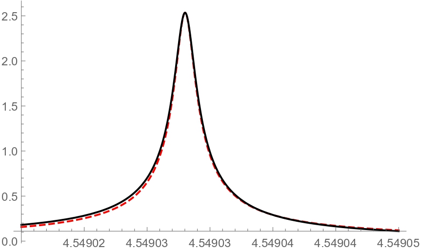
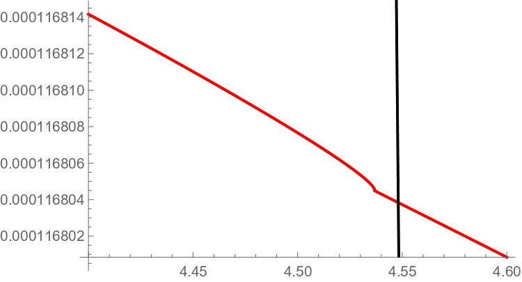
The solid black line in Figure 1 shows (left panel) and (right panel) calculated from (2.6) as a function of . The red dashed line shows a numerical fit to the theoretical curve by a Lorentzian profile (the resonance frequency , width , and the maximal value are the fitting parameters). Two important observations follows from this numerical analysis. First, the contribution of to the induced dipole is negligible (right panel) as (if ), and it contributes only to the background scattering. Second, the scattering is dominated by a resonance (left panel) so that the background scattering can be neglected near the resonance in (2.6).
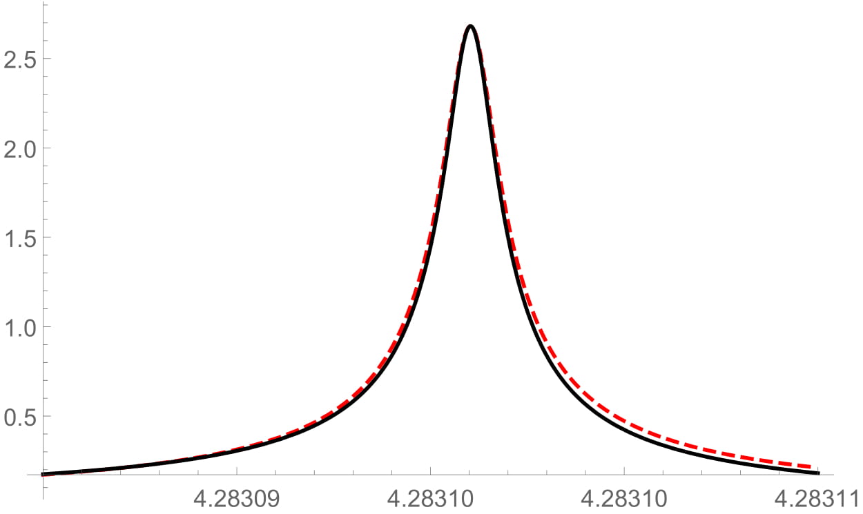
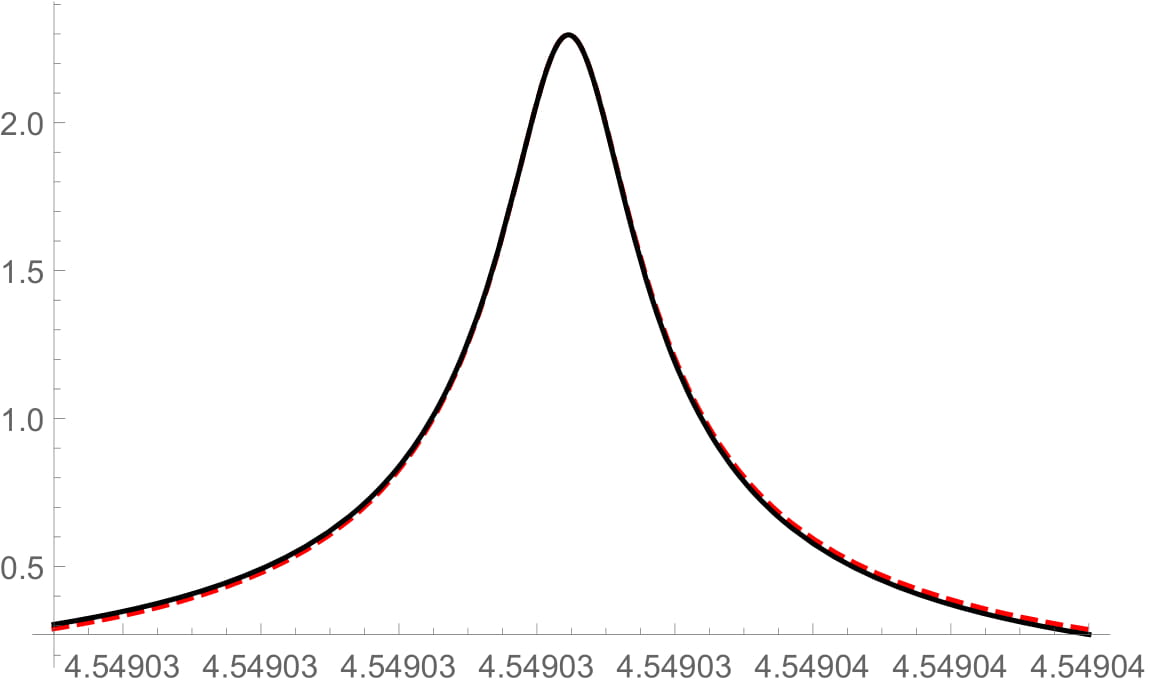
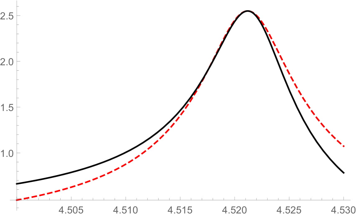
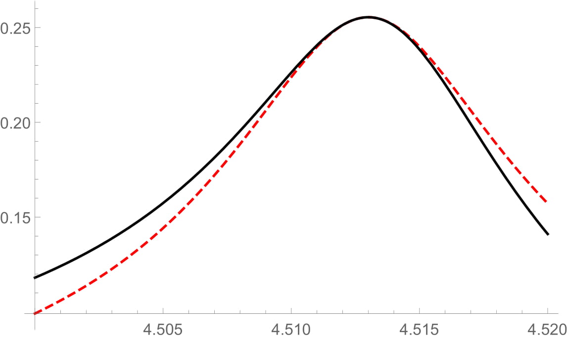
The conclusion holds for significant variations of the system parameters, although the parameters of the Lorentzian profile may change significantly. Figures 2 and 3 display and its fit by a Lorentzian profile for various values of the parameters (indicated in the captions). One can see that the resonance remains relatively narrow under increasing or , while increasing and by an order of magnitude results in a drastic change in the resonance width (as might be seen in Fig. 4). It should be noted, however, that as and increase, the dipole approximation becomes inapplicable so that Eq. (2.6) is no longer valid and one must solve (2.3) by other means. As a point of fact, that the scattering in the system considered is resonance dominated can be proved analytically without all the simplifying assumptions made above. However mathematical details of this study are rather involved and are omitted.
3 A Fabry-Perot interferometer with two propagating coupled modes
Consider a Fabry-Perot resonator made of two resonating scattering interfaces such as the one discussed above. If the distance between the interfaces is large enough so that the evanescent fields near each interface do not contribute to the field on the other interface, then the reflection matrix of this composite structure is:
| (3.8) | |||||
where is the unit diagonal matrix, is the matrix defined by the amplitude of the wave after propagation through a distance , in this case is the distance between the interfaces. It is a diagonal matrix with elements being phase factors corresponding to different group velocities of the modes. A resonance position of the composite system (a pole of ) is defined by the condition
| (3.9) |
The scattering on each interface is further assumed to be resonance dominated (the background scattering can be neglected). This assumption is always justified if the scattering interface is composed of small identical (subwavelength) scatters separated by distances that are much larger than the size of scatterers as in the example presented above. Then the analytic part of the single interface reflection matrix will scale with the volume of the scatter so that the background scattering can be neglected in (2.7) as compared to the resonant part. For the array considered above this approximation holds because is negligible as compared to . In this case, Eq. (3.9) is further simplified to
| (3.10) |
If the polarization modes are decoupled ( is diagonal), then this equation is reduced to the case of light scattering on a dielectric double array [18] where it was shown that, for specific values of the distance , there exists a real root that lies in the radiation continuum, thus indicating a BSC as a resonance with the vanishing width. Here the situation is more complicated as the residue matrix is not diagonal due to the coupling of the compression and sheer modes, and the phase factors in are different for each mode because .
4 BSC in a double array of cylindrical scatters
The existence of BSC depends on the structure of the residue matrix . Its calculation generally requires solving the Lippmann-Schwinger integral equation. If the dipole approximation is applicable, this task is simplified to summation of the dipole radiation. The latter can be done analytically for either a single or double periodic array of thin, long, cylindrical scatter where the longitudinal and transverse polarizations in the plane perpendicular to the cylinders are coupled at the surface of the cylinders. As noted, the transverse mode polarized parallel to the cylinders is decoupled. Therefore the three-dimensional reflection matrix is block-diagonal. The block corresponds to the decoupled transverse mode. A study of BSCs of this mode is essentially identical to the electromagnetic BSCs in one or more open diffraction channels [18, 19].
The block describes two coupled polarization modes (the in-plane longitudinal and transverse modes) in the plane perpendicular to the cylindrical scatters. The poles of the scattering matrix are defined by roots of (3.10). The residue matrix is calculated using the asymptotic expansion of the Hankel function in (2.3) and the Poisson summation formula in (3.10) (much like in the electromagnetic case [19]). Recall that only a special case is considered in which the cylinders have different density compared to the background material but the lame coefficients remain the same. Materials with such properties can be found in [20]. In order to obtain the reflection coefficients one can change coordinates to the in-plane unit polarization vectors: and , where . The position of the resonance pole ( and ) is calculated in the leading order of . Expanding to leading order in one infers that
where , , , and .
It should be noted that , as a result the two in-plane polarization modes are coupled at the interface. It follows from the structure of that . Physically, this is because near the resonance frequency, the elastic field on the scatter lies almost completely parallel to the direction, this means that the reflection amplitudes, , are proportional to because is of higher order in the volume of the scatters (as shown by the right panel of Fig. 1):
This feature of the scattering process is easily understood in the considered dipole approximation. In this case the induced dipole moment of each scatterer is parallel to by the reflection symmetry about the position of each scatterer so that the rows of the reflection matrix are linearly dependent. Therefore, neglecting , near the resonance frequency. Equation (3.10) can be viewed as an eigenvalue problem for the matrix . Since , is always a solution. However, it does not define a pole in (3.8) if has the form (2.7) (all singular factors are cancelled out, this can be seen explicitly by using the unitary condition on the scattering matrices). The other roots determine the poles of the composite structure:
| (4.1) | |||||
A BSC occurs if the imaginary part of the pole can be driven to zero by adjusting parameters of the system. This happens if the phase factors in the numerator in the right side of (4.1) become unit, , that is, both modes satisfy the quantization conditions:
where and are both either mutually even or odd integers. It should be noted that the system has a parity symmetry in the direction. The even/odd integers in the phase factors above corresponds to even/odd parity BSC just as in the scalar case. In contrast to electromagnetic case [18], the quantization conditions cannot be satisfied by adjusting the distance between the arrays because the modes have different dispersions (note the parameter in ). Both conditions can only be fulfilled for a generic parameter if the spectral parameter is such that
for some integers and . It follows from (4.1) that under the stated conditions one of the resonances turns into a BSC at the resonance position of the single array
while the other resonance has a double width and the same position , just like in the electromagnetic case.
A BSC is not coupled to radiation modes, hence, cannot be excited by incident waves. It is a solution to the homogeneous equation (2.3) for the double array that is square integrable in and Bloch-periodic in (Sommerfeld conditions at infinity are satisfied due to square integrability). If the cylinders in a double array are located at , being an integer, then a BSC has a real frequency that lies in the radiation continuum, . Just as in the case of the single array, the scattering matrices are determined by the dipole moment of the central scatter of each array , ( is the elastic field of the double array). The consistency condition on the dipole moment of each central scatter (located at ) results in a system of equations which has a non-trivial solution only if its determinant vanishes, which defines .
It was shown that in the Fabri-Perot limit, for every polarization state , such frequency does exist and , where is the resonance position for a single array if the distance between arrays and satisfy the conditions stated above. The BSC field is given by a similar expression as the scattered field in the right side of (2.5), with necessary modifications in order to account for the second array. By construction of the induced dipoles (without an incident wave), the amplitudes of propagating modes in (2.5) should vanish in the far field when (by the energy flux conservation) so that a BSC solution to the double array decays exponentially
| (4.2) |
as , and, hence, has a finite energy per each period of the array.
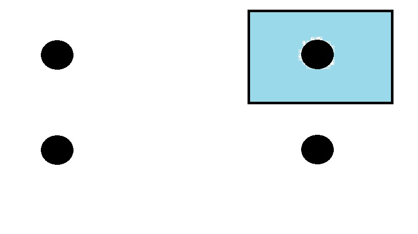
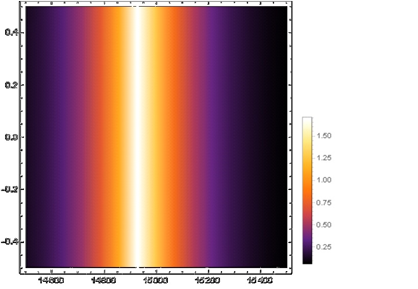
The energy density of a BSC is shown in the middle panel of Figure 4 in unit of . The left panel shows . It is also worth noting that the component of the BCS solution, , so its contribution to the energy density is of higher order in and can be neglected. The parts of the array shown in the middle and right panels corresponds to a region indicated by a rectangle in the left panel where a pictorial representation of the array is shown. As one can see, the energy and the field is concentrated near each array. The displayed BSC has an even parity so that is odd in and , so that the discussed Fabry-Perot limit is satisfied. The material parameters correspond to bulk silicon. According to [20]-[21], the relative density between different samples can be tuned to at least an order of magnitude larger than the relative lame coefficients to justify the simplifying assumption about the lame coefficients. So, the found BSC can also be observed experimentally.
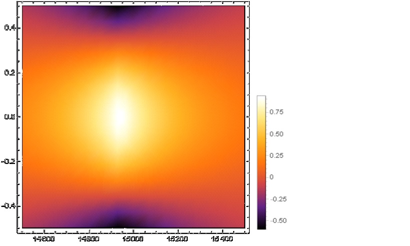
In the frequency range under consideration, the two polarizations decouple for normal incident , the scattering matrix is proved to become diagonal, that is, the longitudinal and transverse wave are decoupled in the first open diffraction channel (which can be understood from the parity symmetry in direction). The transmission coefficient for the transverse mode becomes , which can be realized from the induced dipole radiation analysis presented above. It is therefore clear that a transverse BSC cannot exist in this spectral range. However the longitudinal mode has a resonance, and the longitudinal reflection coefficient is shown to have the Breit-Wigner form near this resonance, hence, BSCs exist. These are single-mode BSCs and have already been discussed in many contexts. For higher diffraction channels the longitudinal and transverse modes are coupled even for . However, the analysis of BSCs in higher diffraction channels becomes mathematically involved even in the single mode case [19] and will not be given here.
5 Conclusions
It was shown that elastic meta-interfaces can be used to obtain BSC via tuning of the cavity width and Bloch phase. Elastic BSC are shown to contain coupled transverse and longitudinal modes that have different dispersion relations. In contrast to previously reported BSC, such as the case of the electromagnetic double array, this elastic BSC requires very peculiar condition on the phases of both the transverse and longitudinal phase, such conditions are necessary in order to tune the far field radiation to zero. This fine tuning is an interesting artifact of the elastic double array which is a major distinction from the BSC previously studied in photonic and acoustic systems. An analytic solution is obtained for such BSC for the first time. Although the stated results have been proved under simplifying assumptions ( and the Fabri-Perot limit), the same dipole formalism can be used in the general case, however this is mathematically involved and will be discussed in a subsequent publication.
Elastic BSCs can be used as elastic wave guides or as resonators with high quality factors in a broad spectral range, especially in view of that elastic systems supporting BSC can be designed using mechanical metamaterials (as materials with desired elastic properties). In particular, owing to a high sensitivity of the quality factor to geometrical and physical properties of a resonating system, elastic BSCs can be used to detect impurities in solids from variations of the density. Understanding the parallels and distinction among wave phenomena in a variety of physical systems is necessary for construction of sensor, filters, lasers, etc. This sort of artificial wave construction will allow one to analyze non-linear phenomena in elastic material in a way similar to the studies done in photonics [25]. The energy density of a high quality resonance (near-BSC state) has shown to exhibit “hot” spots where it exceeds the energy density of the incident wave by orders in magnitudes and would allow one to amplify non-linear effects in solids in a controlled manner.
References
- [1] J. von Neumann and E. Wigner, Phys. Z. 30, 465 (1929)
- [2] F.H. Stillinger and D.R. Herrick Phys. Rev. A 11, 446 (1975)
- [3] C. W. Hsu, B. Zhen, A. D. Stone, J. D. Joannopoulos, and M. Soljačíc, Nat. Rev. Mater. 1, 16048 (2016).
- [4] S.I. Azzam, V.M. Shalaev, A. Boltasseva, and A.V. Kildishev Phys. Rev. Lett. 121, 253901 (2018).
- [5] R. Parker, J. Sound Vib. 4, 62 (1966)
- [6] M.D. Groves, Math. Method. Appl. Sci. 21, 479 (1998)
- [7] M. Zhao and K. Fang, Optic Express 7, 27, 10138 (2019)
- [8] T.Lim and G.Farnell, J.Acoust.Soc.Am.45, 845 (1969)
- [9] A.Maznev and A.Every, Phys.Rev.B 97,014108 (2018)
- [10] G.W. Milton and A.V. Cherkaev, J. Eng. Mater. Technol., 117, 483 (1995).
- [11] K. Bertoldi, V. Vitelli, J. Christensen, and M. van Hecke, Nat. Rev. Mater. 2, 17066 (2017).
- [12] X. Yu, J. Zhou, H. Liang, Z. Jiang, and L. Wu, Prog. Mater. Sci., 94, 114 (2018).
- [13] J.U. Surjadi, L.Gao, H. Du, X. Li, X. Xiong, N.X. Fang, and Y. Lu, Adv. Eng. Mater., 21, 1800864 (2019)
- [14] C. W. Hsu, B. G. DeLacy, S. G. Johnson, J. D. Joannopoulos, and M. Soljačíc, Nano Lett. 14, 2783 (2014).
- [15] A. Taghizadeh and I.-S. Chung, Appl. Phys. Lett. 111, 031114 (2017).
- [16] H.M. Doeleman, F. Monticone, W. Hollander, and A. Alù, A. F. Koenderink, Nature Photonics. 12, 397 (2018)
- [17] E. N. Bulgakov and D. N. Maksimov, Phys. Rev. Lett. 118, 267401 (2017).
- [18] D. C. Marinica, A. G. Borisov, and S. V. Shabanov Phys. Rev. Lett. 100, 183902 (2008)
- [19] R.F. Ngandali and S.V. Shabanov, J. Math. Phys. 51, 102901 (2010)
- [20] O.A. Bauchau and J. I. Craig, Structural Analysis With Applications to Aerospace Structures, Springer (2009)
- [21] J.N. Reddy Wiley, Energy Principles and Variational Methods in Applied Mechanics 2nd Edition, (2002)
- [22] L.D. Landau, E.M. Lifshitz Course of Theoretical Physics, 7, 101 (1959)
- [23] V. Twersky, J. Opt. Soc. Amer. 52, 145-171 (1962)
- [24] F. J. García de Abajo, Rev. Mod. Phys. 79, 1267 (2007)
- [25] R.F. Ngandali and S.V. Shabanov, The resonant nonlinear scattering theory with bound states in the radiation continuum and the second harmonic generation, Proc. SPIE 8808, Active Photonic Materials V, 88081F (2013), DOI:10.1117/12.202827