Graphene Overcoats for Ultra-High Storage Density Magnetic Media
Abstract
Hard disk drives (HDDs) are used as secondary storage in a number of digital electronic devices owing to low cost (0.1$/GB at 2016 prices) and large data storage capacity (10TB with a 3.5 inch HDD). Due to the exponentially increasing amount of data, there is a need to increase areal storage densities beyond1Tb/in2. This requires the thickness of carbon overcoats (COCs) to be2nm. Friction, wear, corrosion, and thermal stability are critical concerns2nm, where most of the protective properties of current COCs are lost. This limits current technology and restricts COC integration with heat assisted magnetic recording technology (HAMR), since this also requires laser irradiation stability. Here we show that graphene-based overcoats can overcome all these limitations. 2-4 layers of graphene enable two-fold reduction in friction and provide better corrosion and wear than state-of-the-art COCs. A single graphene layer is enough to reduce corrosion2.5 times. We also show that graphene can withstand HAMR conditions. Thus, graphene-based overcoats can enable ultrahigh areal density HDDs10Tb/in2.
I Introduction
There has been an incessant increase in data generation over the past few decades, owing to enhanced use of personal computersReinsel2017 , digital electronic productsReinsel2017 , and the continuous growth of automationReinsel2017 . The annual data creation rate was16.1zettabytes/year (ZB, 1ZBtrillion gigabytes (GB)) in 2016Reinsel2017 , and is expected to increase to163ZB/year by 2025Reinsel2017 . While various devices are used to store digital information, such as tapetape and flash drivesGrochowski ; HDDmarket , hard disk drives (HDDs) remain the primary choice as secondary storage device, i.e. as external storage device with a non-volatile memory function that holds data until it is deleted or overwritten, in contrast to primary storage devices, e.g. random access memory or cache, that hold data only temporarily while the computer is running. This is due to their low cost(0.1$/GB at 2016 pricesGrochowski ) and large storage capacity10TB with 3.5 inch HDDsGrochowski . This is reflected in the 425 million HDDs shipped globally in 2016HDDmarket , decreasing to 350 million by 2020HDDmarket , due to the expected increase in storage capacity per drive. HDDs will rule storage technologies at least for the next 5-10 years in terms of capacityGrochowski ; HDDmarket , priceGrochowski ; HDDmarket , productionGrochowski ; HDDmarket and shipmentGrochowski ; HDDmarket . Desktops, laptops, cloud computing, consumer digital electronic products predominantly employ HDDsPiramanayagam ; McFadyen ; Mao . A HDD contains two major components: 1) hard disk medium (HDM)Piramanayagam ; McFadyen ; 2) headMcFadyen ; Mao . In a HDD the information is written in/read from the HDM by the headZhang2010 ; Plumer2011 . To meet the rise of data storage demand, HDD technology has moved from inductive, used prior to 1990McFadyen ; Bajorek2014 , to magneto-resistive from 1990McFadyen ; Bajorek2014 , and giant MR (GMR) or tunneling MR (TMR) heads from 1997McFadyen ; Mao ; Bajorek2014 and 2004 onwardsMcFadyen ; Mao ; Bajorek2014 . HDM technology moved from particulate mediaPiramanayagam in the first generations HDDs in the late 1950sPiramanayagam to thin film mediaKryder1992 ; Piramanayagam after their introduction in the 1980s into 5.35inch drivesKryder1992 ; Piramanayagam . Servo and signal processing technologies have also advancedZhang2010 . Solid state drives (SSDs)Grochowski ; HDDmarket are the main competing technology, posing a threat to future HDD viabilityHDDmarket . The main advantage of HDDs is that they can store a large amount of dataTB cheaply. As of 2019, SSDs are still more than two times more expensive than HDDs: A 1TB internal 2.5-inch hard drive costs$40-50SSD-HDD , while an SSD of the same capacity and form factor starts at$250SSD ; SSD-HDD . The main advantage of SSDs over HDDs is that they do not have mechanically moving parts, making them more stable. The second advantage is that SSDs based on NAND flash memories are faster:10-13s average bootup time for SSDsSSD-HDD , compared to30-40s for HDDsSSD-HDD . Thus, novel technologies are needed to enable high areal density (AD) HDDs with1Tb/in2Grochowski ; 10Marchon2013 .
One option is to reduce the head-media spacing (HMS), since this reduces the signal-to-noise ratio10Marchon2013 ; Wallace2000 and limits the AD growth10Marchon2013 ; Wallace2000 . There are many contributors to the HMS, and for 1Tb/in2, the total HMS is8.9-6.5nm10Marchon2013 , based on the sum of HDM overcoat thickness (2.52.0nm)10Marchon2013 , lubricant thickness (1.21.0nm)10Marchon2013 , touch down height (2.01.0nm)10Marchon2013 , fly clearance (1.21.0nm)10Marchon2013 and head overcoat thickness (2.01.5nm)10Marchon2013 . Thus, the HDM overcoat is the largest contributor. This comprises magnetic/metallic layers, including Co-alloys-based magnetic storage layersPiramanayagam ; Casiraghi2007 , with a high coefficient of friction COF, i.e. ratio of frictional force to normal forcefriction-book ,0.6-0.8Dwivedi2015 ; 15Dwivedi2015b and wearDwivedi2015 ; 15Dwivedi2015b . Therefore, they can experience mechanical damage whenever intermittent contact occurs with the headDwivedi2015 ; 15Dwivedi2015b , and are susceptible to corrosionCasiraghi2007 ; Dwivedi2015 ; Casiraghi2004b and oxidationDwivedi2015 ; 15Dwivedi2015b , leading to HDD degradation or damage. Carbon-based overcoats (COCs) are widely used to protect HDM from mechanical damageCasiraghi2004a ; Casiraghi2004b ; Piazza2004 ; Piazza2005 ; Dwivedi2015 ; Rajauria2015 and corrosionCasiraghi2004b ; Ferrari2004 ; Casiraghi2007 ; 15Dwivedi2015b , to ensure maintained functionality and durabilityCasiraghi2007 ; Ferrari2004 . The COC thickness reduced from 12.5nm in 1990Yogi1990 , corresponding to 1Gb/in2Yogi1990 , to 2.53nm in 2013 for 0.81Tb/in210Marchon2013 ; Dwivedi2015 , with a planned reduction to 1.8-1.5nm for 4Tb/in2 by 2020-202110Marchon2013 . By extrapolating Fig.2 in Ref.10Marchon2013 ,1nm would be required for10Tb/in2. However, current COCs lose most of their appealing properties, such as anti-frictionDwivedi2015 ; 15Dwivedi2015b ; Rajauria2015 , wear resistanceDwivedi2015 ; Rajauria2015 , Young’s ModulusCasiraghi2004a ; Casiraghi2004b ; Casiraghi2005 ; Ferrari2004 , and corrosion protectionCasiraghi2004a ; Casiraghi2004b ; Casiraghi2005 ; Ferrari2004 ,2-3nm. The current2.7nm commercial COCs have high COF0.3-0.5Dwivedi2015 ; 15Dwivedi2015b and wear in a ball-on-disk tribological environmentDwivedi2015 ; 15Dwivedi2015b , which can result in damage, hence durability concerns. The ideal overcoat needs to provide: 1) corrosion protection, which requires complete coverageCasiraghi2007 ; Dwivedi2015 and a layer without any pinholesFerrari2004 ; Casiraghi2007 ; 2) COF0.3-0.5, lower than in 2.7nm commercial COCsDwivedi2015 ; 15Dwivedi2015b and wear resistanceCasiraghi2007 ; Dwivedi2015 ; Rajauria2015 , which requires better lubricating propertiesRajauria2015 ; Dwivedi2015 , hardness and elasticity with a Young’s modulus of at least400GPaCasiraghi2007 ; Casiraghi2004a ; 3) lubricant compatibilityCasiraghi2007 ; 4) surface smoothnessMoseler2005 ; Casiraghi2005 ; Pisana2006 , e.g. root mean square roughness0.2-0.3nmCasiraghi2007 . Given the limitations to achieve most of these properties with conventional COCs2nmCasiraghi2004a ; Casiraghi2004b ; Ferrari2004 , either the search of novel overcoats or engineering of existing overcoats is required to enable future ultra-high AD HDDs.
Another critical bottleneck hindering AD growth is the superparamagnetic limitPiramanayagam ; Plumer2011 ; Richter2007 . In order to increase AD, the grain size of the magnetic recording layer needs to be8-9nmPlumer2011 ; Piramanayagam . Between 2000 and 2010 this was reduced from 20 to 9nmPlumer2011 , to enable denser packing of informationPiramanayagam ; Plumer2011 ; Richter2007 . However, depending on material, superparamagnetism comes into play for grain sizes8-9nmPlumer2011 ; Richter2007 ; Plumer2001 . The reduction of grain size results in a decrease of their magnetic anisotropy energyPlumer2011 ; Richter2007 ; Weller1999 , and the magnetization can randomly flip in response of thermal fluctuationsPlumer2011 ; Richter2007 . For thermal stability of small grains3nm over long periods of time (up to 10 years) the magnetic recording layer must have KV/kTPlumer2011 ; Plumer2001 ; Weller1999 , where Ku=1/2HKMPlumer2011 is the anisotropy constant, HK [A/m] the magnetic anisotropy field, M [A/m] the magnetization, V [m3] is the grain volume, kB the Boltzmann constant and T the temperature. Thus, magnetic materials with large100kOe HK are needed to support grains down to 3nm with stable magnetization, i.e. not in the superparamagnetic limit. E.g., FePt supports stable grains with diameters down to 2-3nmPlumer2001 ; Weller1999 ; Kryder2008 ; Challener2009 . However, higher HK results in higher coercivity, i.e. the resistance of a magnetic material to changes in the magnetization, which is equivalent to the field intensity necessary to demagnetize the fully magnetized material, e.g. up to 50000Oe for FePtPlumer2001 (10000Oe=1T), much larger than in today’s recording heads with1-2TPlumer2011 ; Plumer2001 . This introduces issues for FePt-based HDM, because the writing field must be comparable to the coercivity of the magnetic storage layer in order to encode informationPlumer2011 . These concerns are usually called the ”magnetic trilemma”Plumer2011 . To overcome these issues, heat assisted magnetic recording (HAMR) was suggestedWeller1999 ; Kryder2008 ; Challener2009 . HAMR uses a laser to heat the magnetic medium for1nsWeller1999 in order to decrease its coercivity, bringing the material to its Curie temperature TC, i.e. the T above which the material loses permanent magnetic properties. Above TC, the HDM coercivity becomes comparable to/lower than the head fieldWeller1999 ; Kryder2008 ; Challener2009 ; Hu2017 ; Vogler2016 , where it is writable with a magnetic field0.8T by conventional headsVogler2016 . After cooling to room T, the coercivity goes back to its original value, and data are retainedPlumer2001 .
While HAMR appears to be a solution to all issues, such as small grain size, high magnetic anisotropy and writability, and paves the way to AD increase, it raises concerns on the thermal stability of COCs against laser irradiationJones2014 ; Ji2014 ; Mangolini2013 . As T700-750K for FePtJones2014 ; Ji2014 ; Weller2016 is reached by laser irradiation, the overcoats for HAMR require thermal stability at least up to700-800K to avoid degradation over timeWeller1999 ; Jones2014 ; Ji2014 . Efforts are ongoing to test the thermal stability of HDM overcoats in variable environments, e.g. by using heating techniques such as laser annealingJones2014 ; Ji2014 , thermal annealingMangolini2013 and by changing the thermal treatment timeJones2014 ; Mangolini2013 ; Wang2013 and heating rateJones2014 ; Ji2014 ; Mangolini2013 ; Wang2013 , so as to design HAMR-compatible overcoats. Ref.Jones2014 reported oxidation, degradation, and removal of a5nm hydrogenated amorphous carbon, a-C:H,-based commercial COC (on HAMR-compatible HDM) in HAMR-like conditions, where a pump laser (527nm) was used to heat the sample at a rate106K/sJones2014 , and the exposed area (8m) was analyzed with a probe laser (CW at 476nm, pulsed with chopper) for Raman measurements with 0.25s total irradiation time. Ref.38 also reported degradation of a 4nm thick a-C:H-based commercial COC (on FePt-based HDM) in HAMR-like conditions, when using a 785nm laser, with a spot size1m, power57mW for 1.5ns, with an additional 2.5ns to reach the peak power and another 2.5ns to go back to 0mW, and a cooling time21.8ns before the next heating cycle. The total heating time in Ref.Ji2014 was0.1ms, corresponding to a 5 year drive life or 157.68106s. For an HDD with 0.5106 tracks, 100 rotation/s and laser heating time 1.5ns, the total irradiation time for 5 years is 47.3103ns=47.310-3ms, i.e. less than 0.1ms. In general, commercial a-C:H COCs have shown degradation or structural changes in various heating environments such as laser irradiationJones2014 ; Ji2014 , annealing at 773K at a rate5K/sMangolini2013 , rapid thermal annealing380K/s to930K for1sWang2013 . Better thermal stability was reported in filtered cathodic vacuum arc (FCVA)-based COCs under laser irradiation in HAMR-likeJi2014 ; Kundu2015 and thermal annealing (up to940K) conditionsPathem2014 , for thickness5nm, consistent with the good thermal stability, i.e. no change in sp3 content up to 1100∘C, found in70nm ta-C filmsFerrari1999 . However, FCVA-based COCs are not yet used due to the presence of macro-particles10Marchon2013 ; Teo2002 . Overall, commercial COCs are facing several critical concerns which constitute a barrier to advance existing technology, and may not be integrated with future HAMR technology.
Graphene is an emerging material for lubricationBerman2015 ; Berman2014 ; Berman2014b ; Berman2014c ; Lee2010 ; Egbert2014 , as well as oxidationTopsakal2012 ; Chen2011a and corrosion protectionMartin2015 ; Weatherup2015 ; Prasai2012 ; Raman2012 ; Kravets2014 . Ref.48 reported that single layer graphene (SLG) reduced steel COF from 0.9 to 0.3 with a coating lifetime up to 6500 cycles and decreased wear rate by two orders of magnitude. Multilayer graphene (MLG) (3-4 layers) showed excellent tribological performance with COF0.2, decrease of wear rate by three orders of magnitude and long sliding lifetime up to 47000 cycles on steelBerman2014b . Ref.Berman2015 indicated that SLG exhibits superlubricity, i.e. friction nearly vanishes when used with nanodiamond on Si/SiO2Berman2015 , and reduced friction by two to three times and wear rate by two orders of magnitude for Au-based electrical contactsBerman2014c . SLG was reported to decrease the oxidation and corrosion of NiChen2011a ; Prasai2012 ; Martin2015 ; Weatherup2015 , CoWeatherup2015 , FeWeatherup2015 , PtWeatherup2015 , CuPrasai2012 ; Raman2012 ; Kravets2014 ; Chen2011a and AgKravets2014 . Reduced graphene oxide (RGO) was also used as a barrier coatingSu2014 . Refs.Yu2015 ; Kim2010 reported that SLG has good thermal stability up to 2600K, with thermal conductivity up to2000W/mKYu2015 ; Lee2011 ; Balandin2008 ; Ghosh2008 ; Faugeras2010 ; Seol2010 ; Cai2010 ; Chen2011 . All these characteristics make SLG promising as protective overcoat for both existing and HAMR-based technologies. Current commercial HDM use a layer of perfluoropolyether (PFPE) lubricant (lube)Dwivedi2015 ; Waltman2012 to further reduce friction and wear and minimize surface energy. Given the lubricating and corrosion protection properties of SLG, the need of lube for SLG is unclear. However, exploring compatibility of SLG with lube is critical from the fundamental viewpoint.
Here we use 1-4 layers of chemical vapor deposition (CVD) grown graphene transferred on Co-alloy (current technology) and FePt-based (HAMR technology) HDMs, and test friction, wear, corrosion and thermal stability, as well as lube compatibility. We demonstrate that SLG shows better performances than current 2.7nm COCs on Co-alloy-based HDM, and good tribological properties with a COF0.2 for10000 cycles. Thermal stability tests confirm that SLG on FePt HDM can withstand HAMR-like conditions, without degradation. SLG’s superior performance and its thinness can enable the development of ultrahigh density magnetic data storage, based either on current technology, or on HAMR, or on HAMR combined with bit patterned media (BPM), where the storage layer is patterned into an array of pillars, each representing a single bitbit-patterned . SLG+HAMR+BPM is expected to increase AD10Tb/in2.
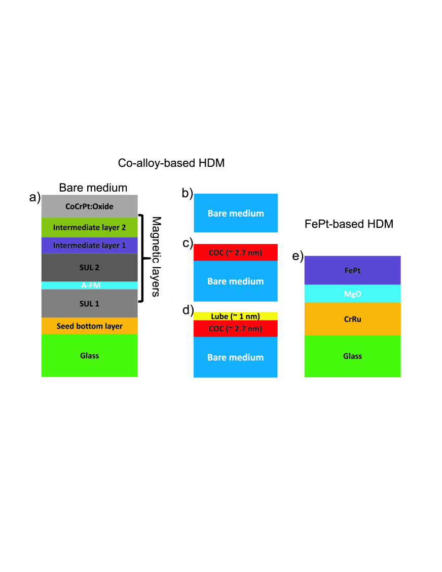
| BM | CoCrPt-oxide based BM without COC and lube |
|---|---|
| BML | CoCrPt-oxide based BM without COC, with PFPE lube (1.20.2nm) |
| CMC | CoCrPt-oxide based commercial magnetic media with commercial COC (2.7nm) without lube |
| CMCL | CoCrPt-oxide based commercial magnetic media with commercial COC (2.7nm) and commercial PFPE lube (1nm) |
| 1LG | SLG on CoCrPt-oxide based commercial magnetic media |
| 2LG | 2LG on CoCrPt-oxide based commercial magnetic media |
| 3LG | 3LG on CoCrPt-oxide based commercial magnetic media |
| 4LG | 4LG on CoCrPt-oxide based commercial magnetic media |
| 1LGL | PFPE lube (1.20.2)nm coated SLG on CoCrPt-oxide based commercial magnetic media |
| 2LGL | PFPE lube (1.20.2)nm coated 2LG on CoCrPt-oxide based commercial magnetic media |
| 3LGL | PFPE lube (1.20.2)nm coated 3LG on CoCrPt-oxide based commercial magnetic media |
| 4LGL | PFPE lube (1.20.2)nm coated 4LG on CoCrPt-oxide based commercial magnetic media |
| 3CF | FCVA-deposited ta-C (0.3nm) on CoCrPt-oxide based commercial magnetic media |
| 6CF | FCVA-deposited ta-C (0.6nm) on CoCrPt-oxide based commercial magnetic media |
| 12CF | FCVA-deposited ta-C (1.2nm) on CoCrPt-oxide based commercial magnetic media |
| 18CF | FCVA-deposited ta-C (1.8nm) on CoCrPt-oxide based commercial magnetic media |
| 8CS | Pulsed DC sputtered sp2 rich carbon (0.8nm) on CoCrPt-oxide based commercial magnetic media |
| 12CS | Pulsed DC sputtered sp2 rich carbon (1.2nm) on CoCrPt-oxide based commercial magnetic media |
II Results
II.1 Magnetic Media Substrates
We use CoCrPt:Oxide-based bare HDMs (BM) from HitachiWaltman2012 . These comprise multiple layers: seed bottom layer, soft-magnetic under layers (SUL), antiferromagnetic layer (A-FM), intermediate layers and CoCrPt:Oxide storage layer, Figs.1a,b. We also use other HDMs from HGSTWaltman2012 : HDM with2.7nm commercial COC (CMC, Fig.1c), and2.7nm commercial COC+1nm commercial PFPE lube (CMCL, Fig.1d). These samples are used as reference. The commercial COC is plasma-assisted CVD (PACVD) grown a-C:H followed by a nitrogen plasma surface treatmentDwivedi2015 ; Goohpattader2015 ; Jones2014 ; Ji2014 ; Mangolini2013 ; Wang2013 ; Waltman2012 . PACVD, magnetron sputtering and FCVA are commonly used to deposit COCsCasiraghi2007 ; Dwivedi2015 ; 15Dwivedi2015b ; Rajauria2015 ; Ferrari2004 ; Casiraghi2004b ; Dwivedi2016c ; Goohpattader2015 ; Jones2014 ; Ji2014 ; Mangolini2013 ; Wang2013 ; Kundu2015 ; Pathem2014 ; Waltman2012 . We also use magnetron sputteringKundu2015 and FCVA to deposit and compare the performance of all types of COCs with that of 1-4LG. COCs with thicknesses from0.3 to1.8nm are deposited on Co-alloy-based HDM using pulsed DC magnetron sputteringDwivedi2016c ; Dwivedi2015c and FCVACasiraghi2007 ; Dwivedi2015 ; Ferrari2004 ; Dwivedi2016c ; Goohpattader2015 ; Kundu2015 ; Pathem2014 ; Ferrari1999 ; Polo2000 ; Fallon1993 . A first COC set is deposited using the NTI Media coating system FS2 FCVA, equipped with a double bend macro-particles filterGoohpattader2015 at an ion energy and dose of 50eV and 3.751015 ions/cm2. The thickness is controlled by varying the deposition time and the rate is calibrated using atomic force microscopy (AFM) and high resolution transmission electron microscopy (HRTEM)Goohpattader2015 . A second set of COCs is prepared using an AJA sputtering toolDwivedi2016c ; Dwivedi2015c . Argon (Ar) plasma cleaning is performed for 3mins, prior to COC deposition, at RF power40W, Ar gas flow rate20sccm and pressure10mTorr to remove surface contaminationDwivedi2015c . 99.999% pure graphite is used as target. The COCs are grown in an Ar atmosphere with pressure and gas flow rate5mTorr and 20sccm. A pulsed DC power100W with 150kHz frequency and duration2.6s is supplied to the graphite target. The deposition time is varied to achieve different thicknesses. The details and nomenclature of the different COCs are listed in Table 1. The structural properties of these FCVA and sputter deposited COCs can be found in Refs.Goohpattader2015 ; Dwivedi2015c . HAMR-compatible FePt-based HDMs are prepared at a base pressure1.810-9Torr by magnetron sputtering. These are stacks of FePt/MgO/CrRu/glass, Fig.1e, where CrRu and MgO seed layersWeller2016 are grown at400∘C and1.5mTorr. The FePt storage layer is grown at600∘C and 3.5mTorr, Table 1.
II.2 Graphene growth and transfer
SLG is grown by chemical vapor deposition (CVD) on a 35m Cu foil following a similar procedure to Ref.Bae2010 . The substrate is loaded into a hot wall tube furnace at1mTorr. The Cu foil is annealed in hydrogen at 1000∘C for 30mins. This reduces the oxide surface and increases the Cu grain sizeBae2010 . The growth process starts when 5sccm CH4 is added. After 30mins the substrate is cooled-down in vacuum (1mTorr) and unloaded.
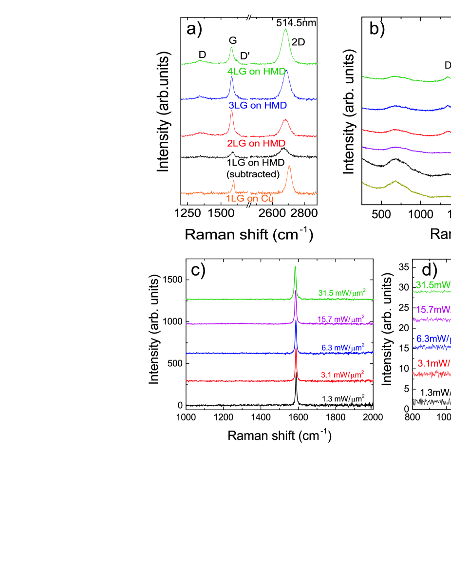
The quality and uniformity of the samples is assessed by Raman spectroscopy. Unpolarized spectra are recorded at 514.5 as well as at 785nm, close to 850nm, used for HAMR writing tests, with a Renishaw InVia spectrometer equipped with a Leica DM LM microscope and a 100x objective with a numerical aperture 0.85. A 514.5nm Raman spectrum of 1LG on Cu before transfer is shown in Fig.2a. The photoluminescence (PL) background due to the Cu foil is removed using baseline subtractionLagatsy2013 . The D to G intensity ratio I(D)/I(G)0.1 indicates a defect concentration ncm-2Ferrari2013 ; Cancado2011 ; Ferrari2000 ; Bruna2014 , Fig.2b. The 2D peak position can be fitted with a single Lorentzian with Pos(2D)=2705cm-1 and full-width-half-maximum, FWHM(2D)33cm-1, a signature of SLGFerrari2006 ; Ferrari2013 . The G peak position and FWHM(G) are1593cm-1 and 16cm-1. I(2D)/I(G), A(2D)/A(G) are2.3 and 4.9.
After Raman characterization, 1LG is placed onto CoCrPt:Oxide. We use a polymethyl methacrylate (PMMA)-based wet transferBonaccorso2012 ; Bonaccorso2010 . First,500nm PMMA is spin coated on the sample. The PMMA/SLG/Cu stack is then placed in an aqueous solution of ammonium persulfate to etch CuBonaccorso2012 . When Cu is fully etched, the graphene/PMMA-stack is placed into de-ionized (DI) water to rinse any acid residuals, and subsequently fished out using the HDM. After drying for one day at room T, the sample is placed in acetone to remove PMMA, leaving 1LG on the HDM. By repeating the steps described above, several 1LGs are transferred to create a MLG stack. The same procedure is used to place 1LG and MLG onto FePt.
Representative Raman spectra of 1-4LG on HDM are in Fig.2a, with HDM spectrum subtracted. This and the spectra of 1L-4LG on HDM before background subtraction are in Fig.2b. By subtracting the reference spectrum, using the N2 Raman peak from air for normalization, from the spectrum taken on 1LG-coated HDM, we can reveal the 1LG contribution. After transfer, all peaks are downshifted and broader, with Pos(2D)2672cm-1, Pos(2D)2681cm-1, Pos(2D)2687cm-1, Pos(2D)2682cm-1, FWHM(2D)61cm-1, FWHM(2D)57cm-1, FWHM(2D)49cm-1, FWHM(2D)53cm-1. Assuming 2686cm-1 as unstrained Pos(2D)Mohiuddin2009 and a rate of change in Pos(2D) with strain Pos(2D)/-64cm-1/%Mohiuddin2009 , this would give0.22% uniaxial strain. This would also explain the rather large FWHM(2D)Mohiuddin2009 ; Yoon2011 . We assume the strain to be mostly uniaxial, because it is unlikely for it to be biaxial, i.e perfectly isotropic in all directions, unless this is induced on purpose such as e.g. in bubblesZabel2012 . There is a small increase in I(D)/I(G) to0.2 for 2-4LG on HDMs.
II.3 Lubricant coating
Commercial HDM with commercial COC and commercial PFPE lube are sourced from HGSTWaltman2012 . We also coat all other samples with PFPE Zdol 4000 as follows. The lube is dissolved in Vertrel XF. The samples are then immersed into and withdrawn from the PFPE solution at0.5mm/s. Before withdrawal the samples are held for 20s to allow the lubricant molecules to adhere. The PFPE-coated samples are then cured at 150∘C for 1.5h. This is done to improve the PFPE bonding to the surfaceDwivedi2015 . The parameters are optimized to obtain a lubricant thickness1.20.2nmDwivedi2015 ; Dwivedi2016c ; Waltman2012 , similar to commercial HDMsWaltman2012 . We also apply PFPE on BM (BML) to examine the tribology of lube containing bare HDM.
II.4 Laser irradiation stability
To test if SLG can withstand HAMR conditions we consider SLG transferred on L10 FePt-based HDMRichter2007 ; Plumer2001 ; Challener2009 ; Hussain2015 and on Si/SiO2. Ref.Hussain2015 achieved TC at1.3mW/m2 by optimizing aperture optics, Ref.Challener2009 suggested to use a laser power density107W/cm2 and0.35107 W/cm2 for FePt-based HDM. We perform Raman measurements at 785nm, the closest available to that used in HAMR (830nmChallener2009 ; Hussain2015 ), with a spot size1.24m, as determined by the razor blade techniquerazor-blade . This involves using a razor blade between objective and sample such that it intersects the beam in a direction perpendicular to its propagation axis, and then moving it from fully covering the beam path until it does not, while measuring the peak intensityrazor-blade . If the profile of the beam is described by a Gaussian, the signal measured by the detector is represented by an integrated Gaussianrazor-blade , i.e. the derivative of the signal will give a Gaussian profile. We perform a line scan perpendicular to an Au contact, while measuring the Si peak intensity as function of scan position. We plot the Si peak intensity as a function of scan position. Taking the derivative of the intensity profile gives a Gaussian, and its 1/e2 width corresponds to the laser spot diameterrazor-blade . We vary the power density from1.3mW/m2 (0.013107W/cm2) to31.5mW/m2 (0.315107W/cm2) in order to examine the laser irradiation-driven evolution of the SLG Raman spectrum under HAMR power densities.
We first consider Si/SiO2/1LG. We record spectra at different power densities for4mins to achieve a good signal to noise ratio. Fig.2c shows that 1LG on Si/SiO2 has no D peak even for the highest power density. Pos(G) downshifts from1588 to 1583cm-1, indicating an increase in T312.5K with respect to RT by taking cm-1/K as shift of Pos(G) with TCalizo2007 . Fig.2d plots the data for 1LG on FePt HDM, with I(G) normalized to that at 1.3mW/m2. In this case, the FePt substrate is rotated at 4100rpm on a circular track with diameter4mm to simulate rotating HDD conditions, with a 20mins acquisition time, much larger than the total laser irradiation time expected for a 5-years life of HAMR-based HDDsJi2014 . No D peak is seen for all power densities, thus confirming the stability of 1LG.
II.5 Friction and wear
Since in HDDs the HDM spins during operation, friction and wear need to be examined in a setup mimicking the HDD operation. AFM and other tip-based tools are used to measure friction and wearLee2010 ; Egbert2014 . In contrast to setups with rotating geometry, tip-based tools measure based on the movement of the tip in the lateral directionLee2010 ; Egbert2014 . Ball-on-disk measurements (rotation based geometry) have a similar assembly as HDDs, with samples rotating while the counterface is in contact with the surfaceDwivedi2015 ; Berman2015 , thus measuring friction. We perform ball-on-disk tests using a nano-tribometer (CSM Instruments) in a cleanroom to have controlled environment with T=231∘C and a relative humidity (RH)555%. A sapphire ball (Al2O3) of diameter2.00.1mm and surface roughness5.00.1nm is used as the counterface, because the HDH is made of an Al2O3-based composite10Marchon2013 . During the test, a normal load20mN and a rotational speed100rpm corresponding to a linear speed2.1cm/s for 10000 cycles are used. Since in HDDs the contact occurs occasionally10Marchon2013 , 10000 cycles in our setup are much higher than the operational lifetime of HDDs. After each test, the wear track and ball images are captured using an optical microscope. To check repeatability, tests are performed 2-7 times.
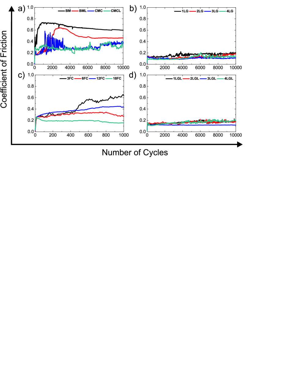
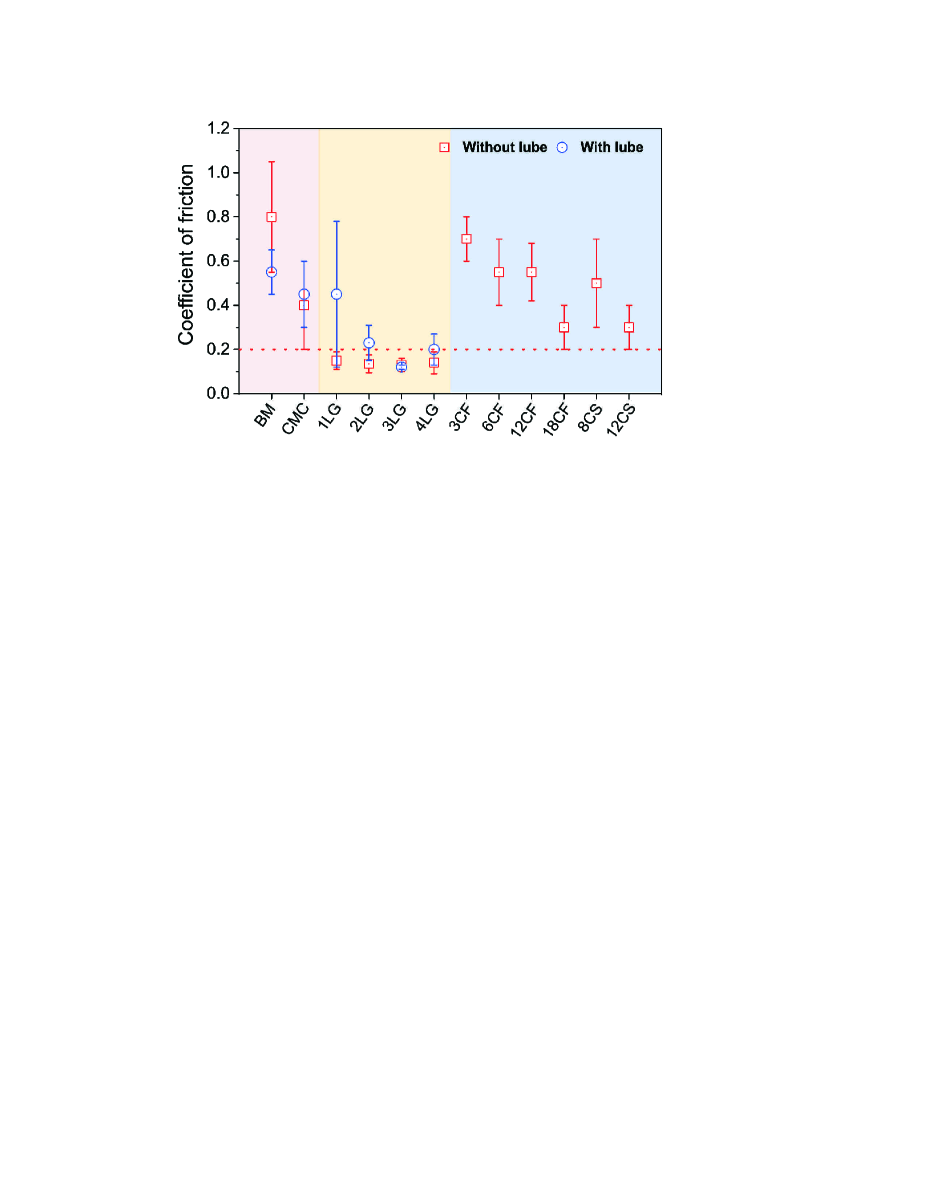
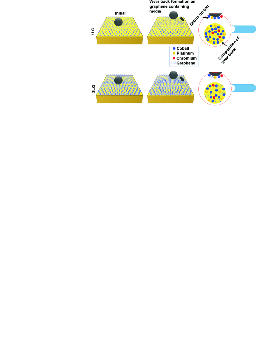
Figs.3a-c plot representative friction curves for BM, CMC, CMCL and BML (Fig.3a) coated with 1-4LG (Fig.3b), and media coated by FCVA (Fig.3c). The average COFs are in Fig.4, including media coated by DC-sputtering. BM has the highest COF0.8, with substantial wear as confirmed by optical images of balls and wear tracks in Figs.6,7. The COF of2.7nm CMC reaches0.4 at 10000 cycles, but with strong fluctuations between0.2 and 0.6 at 1500 up to 3500 cycles, Fig.3a, and negligibly improves wear with respect to BM, Fig.3a. The transfer of 1-4LG reduces COF below 0.2 for all samples, and gives non-fluctuating, smooth friction curves. Furthermore, the COF for 1-4LG-coated samples (without lube) is4 times lower than BM and2 times lower than CMC, despite a reduction of thicknesses7 times (for 1LG) to 2 times (for 4LG) with respect to CMC. Figs.6b,d,7b,d reveal that the wear track width of 1-4LG-coated samples is2-4 times lower and debris transferred to the ball are smaller than BM and CMC, indicating higher wear resistance. All FCVA COCs with thicknesses from0.3 to1.8nm show2 to 5 times higher COF than 1-4LG-coated samples with and without lube, apart from 1LG without lube. Pulsed DC sputtered COCs have2-3 times higher COF than 1-4LG-coated samples.
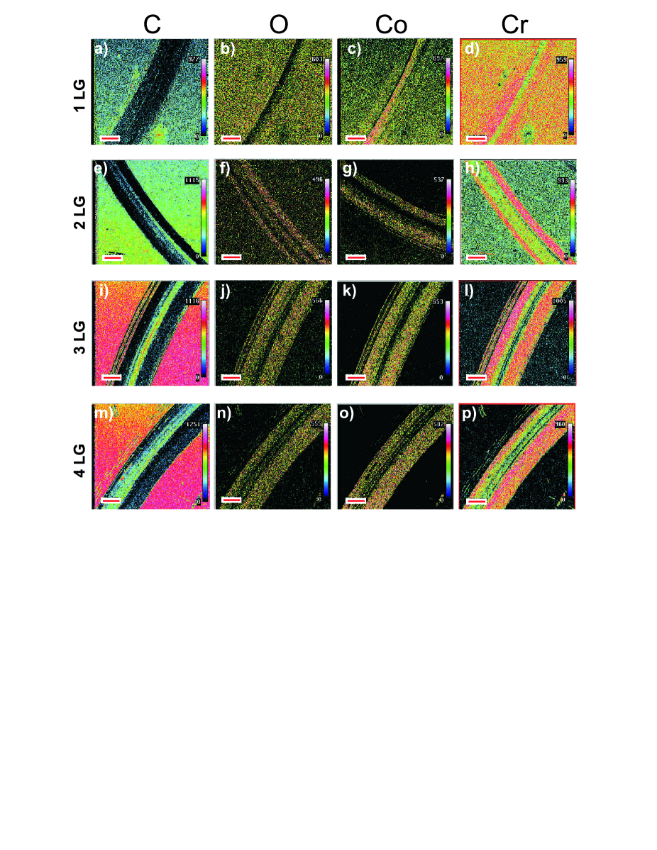
To further analyze the wear tracks, Auger Electron Spectroscopy (AES) imaging is performed using a JEOL JAMP Auger Microprobe, Fig.5. Before recording AES images, scanning electron microscope (SEM) images are taken to select the AES locations. The AES images inside and outside the wear tracks show the carbon-containing sites and that the amount of carbon on the wear track increases with increasing number of graphene layers N. The Co and Cr intensities inside the wear tracks are higher for 1LG, and decrease with increasing N, due to the increase in C and1-3nm sampling depth of AESAES ; AES1 ; AES2 . The O signal in the wear track appears due to ambient oxygen as the samples are exposed to air before AES, with some contribution from the media oxide.
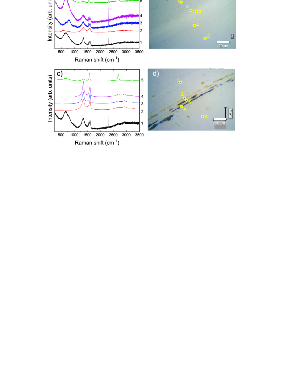
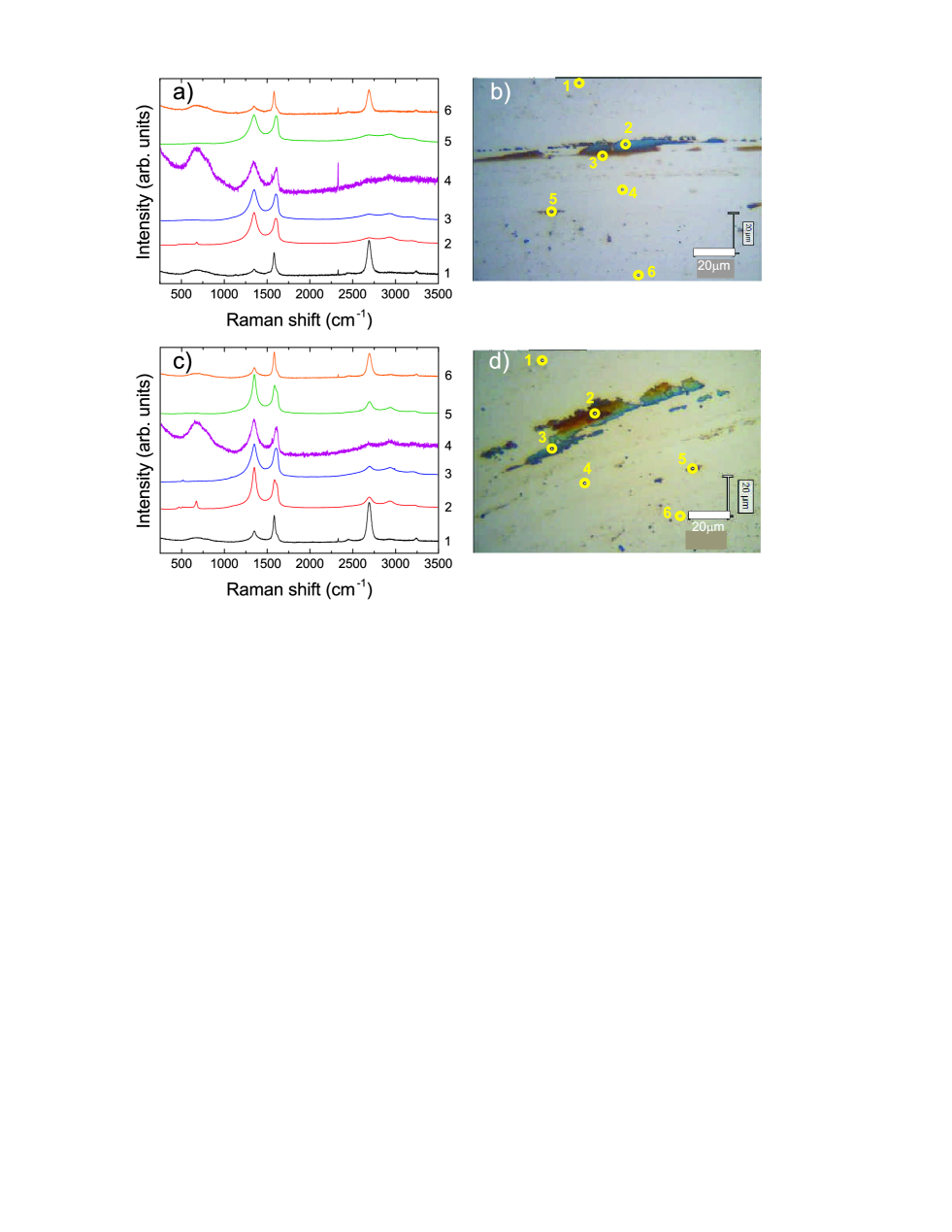
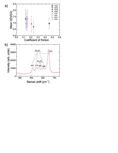
After ball-on-disk tests, the wear tracks are analyzed by Raman spectroscopy. Ref.Ferrari2000 introduced a three stage model of amorphization. Stage 1: graphene to nanocrystalline graphene. Stage 2: nanocrystalline graphene to low sp3 amorphous carbon. Stage 3: low sp3 amorphous carbon to high sp3 amorphous carbon. For all spectra in Figs.6,7, as the D peak increases, D’ and D+D’ appear, whereas the 2D peak intensity weakens when approaching the wear track, indicating an increase in disorder according to stage 1. The broad peak between 500 and 1000cm-1 is due to the glass substrateWhite1984 ; Affatigato . At the centre of the wear track, all second order Raman features (i.e. 2D, 2D’ and D+D’ peaks) merge, while I(D) decreases and D,G become broader, indicating an increase of disorderFerrari2000 . 2-4LG are less damaged than SLG, as for the spectra in Figs.6a,c and I(D)/I(G) in Fig.8a, from at least 5 positions as a function of COF without and with lubricant (L). Overall, there seems to be no significant trend of I(D)/I(G) with COF. However, a difference is seen without lubricant: I(D)/I(G) is 0.95 and 1.0 for 3-4LG, while for 1-2LG it is 1.33 and 1.25. Thus, there are less defects in 3 and 4LG compared to 1 and 2LG. The peaks below1000cm-1 in Fig.8a are due to the underlying HDM: Those470cm-1 (Eg), 513cm-1(F2g), 606cm-1(F2g), 673cm-1 (A1g) are from Co3O4Gallant2006 ; Hadjiev1988 , while the Ag mode550cm-1 is from Cr2O3Banerjee2014 .
II.6 Effect of lubricant
Friction measurements on lube-coated samples (Figs.3d,e) show that the COF of 2-4LG is similar to their non-lubricated counterparts, suggesting that 2-4LG without lube are lubricious enough and that the lube does not improve lubricity. Lube on 1LG results in higher and inconsistent friction and wear, as some measurements show lower COF0.15, some higher0.78, with friction increasing after few thousands cycles. The COF of 1LG, on an average, is0.45, i.e.3 times its non-lubricated counterpart. The D and G peaks in the Raman measurements in Figs.6,7 on 1-4LG confirm the presence of carbon on the wear tracks and transfer of debris to the balls, similar to the non-lubricated case.
II.7 Corrosion
Co-alloys have great propensity to corrode, mainly due to Co oxidationTomcik2000 . This results in the loss of magnetic propertiesTomcik2000 , giving one of the major concerns for long-term functionality and durability of HDDsCasiraghi2007 ; Dwivedi2015c ; Tomcik2000 . To examine the corrosion protection efficiency of 1-4LG and compare their performance with state-of-the-art COCs, the corrosion of different uncoated- and coated-HDM, exposed to an electrolyte solution0.1M NaCl similar to that used in Refs.Tomcik2000 on a0.24cm2 area, is investigated using an electrochemical corrosion methodDwivedi2016c ; Tomcik2000 . The measurements are performed with a 3-electrode setup with a Pt wire as counter electrode, Ag/AgCl as reference electrode and HDM as working electrode, to which the potential is appliedDwivedi2015c . Each test consists of anodic and cathodic sweeps, where the potential is varied and the corresponding current measuredDwivedi2015c . Every sweep is conducted at different locations, with at least 3 sets of 6 sweeps on each sample. The so-called Tafel’s analysisTomcik2000 ; Stansbury is done by plotting anodic and cathodic curves on a semi-logarithmic scale of potential versus log current. The linear part of the logarithmic anodic and cathodic currents are extrapolatedTomcik2000 ; Stansbury , and the intercept of these lines gives the corrosion currentTomcik2000 ; Stansbury , and the corrosion current density J when divided by the contact area. The corrosion protection efficiency (CPE), a parameter which defines how efficient the overcoat is in protecting against HDM corrosion, is estimated asDwivedi2016c :
| (1) |
where is the corrosion current density of BM and J that of coated HDM.
When a metal is exposed to a corrosive solution, it releases ions that leave behind electrons, which can be observed in an anodic reactionTomcik2000 as:
| (2) |
where M is the metal and n the number of electrons released. For Co-alloy-based systems, metal dissolution, decreasing anode conductivityTomcik2000 , can take placeTomcik2000 :
| (3) |
As the corrosion reaction involves the transfer of electrons and ions between metal and solutionTomcik2000 , the corrosion rate varies with corrosion currentTomcik2000 , hence J varies inversely with corrosion resistance, i.e. the COC ability to reduce the HDM corrosionDwivedi2016c ; Dwivedi2015c ; Tomcik2000 . The BM shows the highest J, indicating the greatest propensity to corrode, Fig.9. J decreases and CPE increases with increasing N. 1LG reduces J2.5 times with respect to BM, but it is twice that of HDM with 2.7nm commercial COC. For 2LG, J is3.8 times smaller than BM, and comparable to CMC. This is remarkable as the 2LG thickness0.7nm, is4 times lower than CMC with2.7nm COC. J then marginally reduces for increasing N. Fig.9 shows that, for similar thickness, graphene-based overcoats have lower J than amorphous COCs, indicating greater protection. The CPE of 2-4LG is similar to thicker commercial CMC and higher than amorphous COCs of similar thickness.
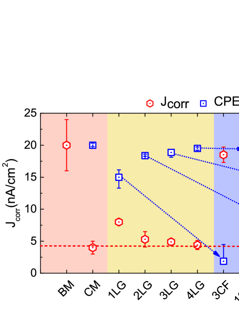
The COC defects and pinholes are the active corrosion sitesTomcik2000 , and their conductivity could further add galvanic corrosionTomcik2000 . The COC should be defect and pinhole-free, smooth and with excellent barrier properties to minimize HDM oxidation and corrosion. Ref.Prasai2012 showed that 1LG can be used as corrosion barrier for metallic surfaces provided it is uniform and defect-free. In our case 1LG reduces corrosion2.5 times with respect to BM. 2LG results in3.8-fold reduction in J with respect to BM, and its J approaches that of4times thicker commercial COC. At and beyond 2LG, J and CPE remain similar, adding marginal anti-corrosion improvement, Fig.9. The higher corrosion protection in 2-4LG with respect to 1LG is mainly due to the fact that the increase in N improves the coverage of HDM, leading to reduction of active corrosion sites.
III Discussion
Friction is defined as resistance to slidingBerman2014 ; Bowden1942 ; Postnikov1964 . At the macroscopic level, Amonton’s lawBowden1942 ; Postnikov1964 states that the frictional force between two bodies varies proportionally to the normal force. Hence:
| (4) |
where F[mN] is the frictional force and W[mN] is the normal force.
Amonton’s law does not take into account the area of contact at the microscopic levelBowden1942 . Ref.Bowden1942 suggested that the contact between two bodies contains several smaller contacts, called asperities, with the sum of the area of these asperities being lower than the apparent macroscopic areaBowden1942 . Thus, from Ref.Bowden1942 , F in micro-tribology can be expressed as:
| (5) |
where is the shear strength, i.e. the stress required to shear the contacting interfaces and enable slidingfriction-book2 , expressed as shear force/area and is the sum of the asperities areas, also called real contact areaBowden1942 . Hence, friction also depends on . Materials with lower strength than the contacting bodies undergo plastic deformationBowden1942 , which depends on WBowden1942 :
| (6) |
where [N/m2] is the flow pressure, i.e. the ratio of force required to displace a material, e.g. a metal, from the slides in a friction measurement setup divided by the cross-section of the torn trackBowden1942 . Thus, Eqs.4,5,6, give:
| (7) |
A Co-alloy is mechanically softerLiu2002 than Al2O3Reidl2012 . When a metallic Co-alloy slides against Al2O3, it causes the HDM surface to undergo plastic deformationBowden1942 ; Postnikov1964 , generating wear and high COF0.8, Figs.3,4. This is consistent with the friction results for metallic surfaces in Refs.Bowden1942 ; Postnikov1964 . This could be due to the formation of an adhesive contact at the HDM-ball interface enabled by the high surface energy of Co-alloy-based HDM42.8mN/mRana2016 and the presence of contaminants at the interface that may enhance the interaction between the two bodiesLi2016 . When 1LG is placed on HDM, the COF decreases4 times and negligibly changes with N.
At the nanoscale, the friction of 1LG on Si/SiO2 against Si tips, measured at a low load1nN and scan speed1-10m/s, was explained based on out-of-plane deformation in front of a scanning probe tip, the so-called puckering effectLee2010 ; Li2010 . This enhances the contact area, hence friction. The out-of-plane deformation is suppressed with increasing NLi2010 , resulting in reduced COF. This theory is not applicable to 1-4LG, due to the significantly larger dimension (ball diameter2.00.1mm) of the counterface, much higher load20mN and higher speed100rpm or 2.1cm/s, which do not differentiate the frictional characteristics of 1-4LG. Thus, all coated media show similar friction, Fig.3b.
1LG is mechanically strongLee2008 ; Lee2013 . It reduces the surface energy of various surfacesWang2009 ; Shin2010 ; Rafiee2012 and can lead to incommensurate tribological contactsBerman2015 between magnetic media and counter-face. Thus, compared to BM, the COF reduction of 1-4LG-coated media could be attributed to 1LG’s mechanical properties: breaking strength42 Nm-1Lee2008 , Young’s Modulus1TPaLee2008 , flexibility (1LG can be stretched up to20% without breakingLee2008 ; Bunch2007 ), reduced adhesive interaction (lower surface energy)Lee2013 ; Wang2009 ; Shin2010 ; Rafiee2012 , as well as incommensurability of the lattice planes sliding against each other at the tribological interfaceBerman2015 , i.e. the hills of one surface with lattice spacing a do not match the valleys of the other surface of lattice spacing b, such that the ratio b/a is an irrational numberincommensurate . This is consistent with what suggested in Ref.Berman2014b for 3-4LG on Si/SiO2 sliding against an a-C:H-coated steel ball, and for 1, 3-4LG on a steel substrate sliding against a steel ballBerman2014b in macroscale ball-on-disk conditions, with a normal force in z direction N0.53N and speeds0.625cm/sBerman2015 ; Berman2014b . Since graphene layers are coupled by van-der-Waals forces, they shear easilyDaly2016 ; Berman2013d ; Wang2017 ; Ruiza2015 , as their interfacial shear strength is low, with a shear force per unit area=12.81018Nm-3Tan2012 and a resulting shear modulus of C44=4.3GPaTan2012 . The ease of shearing further aids the reduction of friction in 2-4LG.
The AES on the wear tracks and Raman measurements across the wear tracks, after ball-on-disk tribological tests, in Figs.5,6,7 show that a carbon signal is still present in all 1-4LG samples, even though disorder-induced peaks appear. Refs.Marchetto2012 ; Marchetto2015 also found carbon on wear tracks after micro-scale friction and wear tests of graphene on SiC. The counterface also reveals transferred debris, consisting of disordered carbon and underlying substrate atoms. This implies that when 20mN is applied and the sample rotates at2.1cm/s, 1LG could turned into patches, due to the large,20mN, contact load. Refs.Marchetto2012 ; Marchetto2015 reported transformation of continuous layers of 1-2LG into 1 and 2LG patches during microscale tribology, despite using a lower load0.11mN and lower speeds30-50m/s than us. This leads to a distribution of 1LG patches along the wear track and transfer of 1LG-containing debris on the counterface. This also happens for 2-4LG coated media. Raman measurements in Figs.6,7 show disordered carbon on the wear tracks, with disorder lower than 1LG, as revealed by I(D)/I(G), Fig.8. This implies that 1LG acts as lubricant when in contact with another 1LG and is not completely removed during tribological tests. AES also reveals a progressive increase in the amount of carbon and carbon-containing sites on the wear tracks with increasing N. The debris transferred to the ball also contain carbon. Therefore, the formation of disordered carbon debris on both surfaces facilitates smooth sliding, and contributes to maintaining the low COF. The marginally lower friction in 2-4LG as compared to 1LG can be linked to I(D)/I(G), Fig.8a, with lower disorder corresponding to lower friction, although this does not apply for lube-containing all-1-4LGL samples. Fig.11 schematically represents the proposed mechanism for friction reduction for 1 and 3LG-coated HDM, where carbon debris are on both ball and wear track.
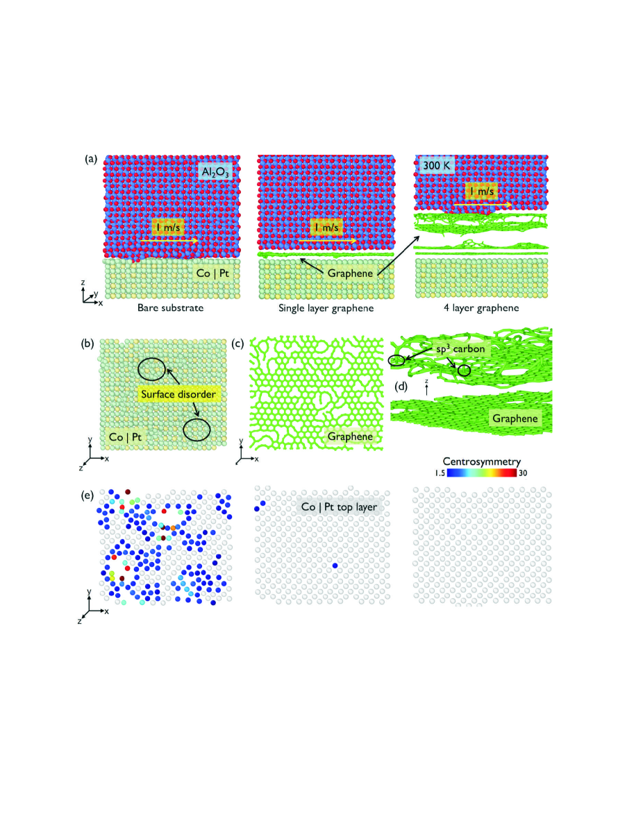
To validate these assumptions, we perform molecular dynamics (MD) simulations of a Co—Ptsapphire system with and without 1 and 4LG. Since Co-alloy-based HDM contain70-75% Co and15-20% Pt (total Co—Pt90-95%)Piramanayagam ; Dwivedi2016c ; Tomcik2000 , we use Co—Pt to mimic our Co-alloy-based HDM. The simulations are performed using the reactive force field (ReaxFF)Duin2001 ; Zhang2004 interatomic potential in order to describe the interactions between C in 1 and 4LG, Al and O in sapphire. The potential parameters for C/Al/O interactions are obtained from Refs.126; 127. The Co—Pt substrate is assumed to be a fixed wall. This is reasonable, as the goal is to demonstrate that the honeycomb structure of 1 and 4LG, as interfacial layer between AlOx and Co—Pt, does not undergo significant changes, i.e. structural disorder, due to friction at 300K, even with a sliding velocity1m/s. In addition, no chemical reactions occur between 1 or 4LG and AlOx. This indicates that it is sufficient to use van-der-Waals interactions to describe the cross-interactions between different elements. For more efficient simulations, the cross-interaction across the Al2O3—1LG—CoPt interface is described by the 126 Lennard-Jones (LJ) potentialAgrawal2002 . The interactions in 1 and 4LG are described by the bond-order Tersoff interatomic potentialTersoff1988 . The final MD simulations are performed in a large-scale atomic/molecular massively parallel simulator (LAMMPS)Plimpton1995 with hybrid/overlay pairs. AlOx is described by the embedded-atom method (EAM)Zhou2004 parameters developed as part of the charge-transfer ionic potential (CTIP) formalismZhou2004 ; Streitz1994 . The interactions in 1 and 4LG are described by the Tersoff potential of Ref.133, while the Co—Pt substrate is described by the EAM potential of Ref.131. All cross-interactions are described via the LJ potential with parameters obtained using Lorentz-Berthelot mixing rulesAllen1990 . Since the aim of the MD simulations is to check and understand whether 1 or 4LG can minimize friction and surface disorder or wear of HDM, the duration is restricted up to when the HDM experiences significant surface disorder and large friction:350ps.
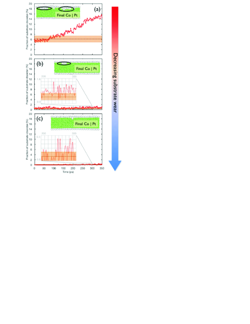
Figs.10a-e,12a-c compare the computed COF and surface disorder of Co—Pt, 1LG and 4LG. The surface disorder represents the friction induced damage/wear of the HDM, and its value is derived considering 0% surface disorder before friction measurements. The amount of disorder in HDM is quantified using the centrosymmetry parameter, which is a measure of the local lattice disorder around an atomKelcher1998 . This is 0 for a perfect latticeKelcher1998 , whereas when point defects exists, i.e. when the symmetry is broken, it assumes a larger positive valueKelcher1998 .
The simulations indicate that BM develops substrate disorder up to14.5% within 350ps, Figs.10b),e),12a). High wear is also observed for BM in the experiments in Fig.3a). The COF averaged over the final 50ps is0.90.1. 1LG reduces the average simulated COF to0.2. Fig.10c shows that 1LG maintains its structural integrity with fraction of disorder1% on average, as a consequence of the low COF between the blocks, indicating higher resistance to wear as compared to BM. 4LG further improves the tribological behaviour. The COF drops to0.1 and substrate disorder is reduced to0.1%, much lower than BM, suggesting that the BM surface remains mostly unaffected. Simulations suggest partial transfer of graphene patches to the sapphire ball. The Raman analysis of wear tracks in Figs.6,7 shows tribo-induced disorder and transfer of carbon to the ball. Thus, the presence of patches containing debris on both surfaces is responsible for the lower COF in 1-4LG-coated HDM, maintaining higher wear resistance than BM.
IV Conclusions
1-4LG-coated media can overcome the tribological and corrosion issues of current Co-alloy-based HDM, with laser irradiation stability on FePt-based HDM for future HAMR. The overall performance exceeds that of thicker commercial COC, as well as other amorphous carbons of comparable/higher thicknesses prepared by FCVA and sputtering. Given the tribological, corrosion and thermal stability characteristics coupled with a thickness7 times (for 1LG) to2 times (for 4LG) lower than state-of-the-art COCs, 1-4LG-based overcoats can meet the requirements for4Tb/in2 AD HDDs (1.5-1.8nm)10Marchon2013 and enable the development of ultrahigh AD10Tb/in2 and HDDs for HAMR when coupled with BPM. Our results imply that2LG-based coatings could be used as tribological interface for various other materials/devices, such as micro- and nano-electromechanical systems.
V Acknowledgments
We acknowledge funding from the National Research Foundation, Prime Minister’s Office, Singapore under its Competitive Research Programme (CRP Award No. NRF-CRP 4-2008-06), the EU Graphene Flagship, EU grant CareRAMM, ERC Grant Hetero2D, EPSRC Grants EP/K01711X/1, EP/K017144/1, EP/N010345/1 and EP/L016057/1, EU grant Neurofibres, the National Energy Research Scientific Computing Center, a DOE Office of Science User Facility, supported by the Office of Science of the U.S. Department of Energy under Contract DE-AC02-05CH11231, the Center for Nanoscale Materials by the U.S. Department of Energy, Office of Science, Office of Basic Energy Sciences, under Contract DE-AC02-06CH11357.
References
- (1) D. Reinsel, J. Gantz, J. Rydning, J. Data age 2025. IDC White Paper 1-25 (2017).
- (2) S. Furrer, M. A. Lantz, P. Reiniger, A. Pantazi, H. E. Rothuizen, R. D. Cideciyan, G. Cherubini, W. Haeberle, E. Eleftheriou, J. Tachibana, N. Sekiguchi, T. Aizawa, T. Endo, T. Ozaki, T. Sai, R. Hiratsuka, S. Mitamura, A. Yamaguchi, BP02, The 28th Magnetic Recording Conference (TMRC 2017).
- (3) E. Grochowski and P. Goglia, Magnetic hard disk drive today’s technical status and future. https://www.snia.org/sites/default/files/SDC/2016/ presentations/keynote_general/Grochowski-Goglia_Magnetic_Hard_Disk_Drive.pdf
- (4) WW HDD market declining to 395 million units shipped in 2017-statista. Storage Newsletter (2017). https://www.storagenewsletter.com/2017/10/10/ ww-hdd-market-declining-to-395-million-units/-shipped-in-2017-statista/
- (5) S. N. Piramanayagam, J. Appl. Phys. 102, 011301 (2007).
- (6) I. R. McFadyen, E. E. Fullerton and M. J. Carey, MRS Bull. 31, 379-383 (2006).
- (7) S. Mao, et al. IEEE Trans. Magn. 42, 97-102 (2006).
- (8) T. Zhang, G. Mathew, H. Zhong and R. Micheloni, Modern hard disk drive systems: fundamental and future trends, in memory mass storage, editors Campardo, G., Tiziani, F. & Iaculo, M. 169-212 (2010).
- (9) M. L. Plumer, J. van Ek, W. C. Cain, Phys. Canada 67, 25-29 (2011).
- (10) C. H. Bajorek, ”Magnetoresistive (MR) Heads and the Earliest MR Head-Based Disk Drives: Sawmill and Corsair”. Computer History Museum, Mountain View, CA. (2014).
- (11) M. H. Kryder, Thin Solid Films 216, 174 (1992).
- (12) https://uk.crucial.com/gbr/en/learn-with-crucial/ about-ssd/ssd-vs-hdd, Micron Technolgies (2017)
- (13) https://www.storagereview.com/ssd_vs_hdd (2018).
- (14) B. Marchon, T. Pitchford, Y. Hsia, S. Gangopadhyay, Adv. Tribol. 2013, 521086 (2013).
- (15) R. L. Wallace, Bell System Technology Journal 30, 1145-1173 (2000).
- (16) C. Casiraghi, J. Robertson, A. C. Ferrari, Mater. Today 10, 44-53 (2007).
- (17) F. P. Bowden, D. Tabor, Friction: An introduction to tribology, Anchor Press (1973).
- (18) N. Dwivedi, et al., Sci. Rep. 5, 11607 (2015).
- (19) N. Dwivedi, R. J. Yeo, N. Satyanarayana, S. Kundu, S. Tripathy, C. S. Bhatia, Sci. Rep. 5, 7772 (2015).
- (20) C. Casiraghi, A. C. Ferrari, J. Robertson, R. Ohr, M. V. Gradowski, D. Schneider, H. Hilgers, Diam. Rel. Mats. 13, 1480 (2004).
- (21) C. Casiraghi, A. C. Ferrari, R. Ohr, D. Chu, J. Robertson; Diam. Rel. Mats. 13, 1416 (2004).
- (22) F. Piazza, D. Grambole, L. Zhou, F. Talke, C. Casiraghi, A. C. Ferrari, J. Robertson; Diam. Rel. Mats. 13, 1505 (2004); A. C. Ferrari; Surf. Coat. Technol. 180 , 190 (2004)
- (23) F. Piazza, D. Grambole, D. Schneider, S. Casiraghi, A. C. Ferrari, J. Robertson; Diamond Relat. Mater. 14, 994 (2005)
- (24) S. Rajauria, S. V. Canchi, E. Schreck, B. Marchon, Appl. Phys. Lett. 106, 081604 (2015).
- (25) A. C. Ferrari, Diam. Relat. Mater. 180-181, 190-206 (2004).
- (26) T. Yogi, T. A. Nguyen, S. E. Lambert, G. L. Gorman, G. Castillo, IEEE 26, 2271 (1990).
- (27) C. Casiraghi, A. C. Ferrari, J. Robertson; Diamond Relat. Mater. 14, 913 (2005).
- (28) M. Moseler, P. Gumbsch, C. Casiraghi, A. C. Ferrari, J. Robertson; Science 309, 1545 (2005);
- (29) S. Pisana, C. Casiraghi, A. C. Ferrari, J. Robertson; Diam. Relat. Mater. 15, 898 (2006).
- (30) H. J. Richter, J. Phys. D Appl. Phys. 40, R149-R177 (2007).
- (31) M. L. Plumer, J. van Ek, D. Weller, The physics of ultrahigh density magnetic recording. Springer series in surface sciences, 1-352 (2001).
- (32) D. Weller and A. Moser, IEEE Trans. Magn. 35, 4423-4439 (1999).
- (33) M. H. Kryder et al., Proc. IEEE 96, 1810-1835 (2008).
- (34) W. A. Challener et al., Nat. Photonics 3, 220-224 (2009).
- (35) Y. Hu, H. Wu, Y. Meng, D. B. Bogy, J. Appl. Phys. 122, 134303 (2017).
- (36) C. Vogler, C. Abert, F. Bruckner, D. Suess, D. Praetorius, J. Appl. Phys. 120, 153901 (2016).
- (37) P. M. Jones, J. Ahner, C. L. Platt, H. Tang, J. Hohlfeld, IEEE Trans. Magn. 50, 3300704 (2014).
- (38) R. Ji, Y. Ma, M. Shakerzadeh, H. L. Seet, J. F. Hu, Surf. Interface Anal. 46, 204-208 (2014).
- (39) F. Mangolini, F. Rose, J. Hilbert, R. W. Carpick, Appl. Phys. Lett. 103, 161605 (2013).
- (40) D. Weller, G. Parker, O. Mosendz, A. Lyberatos, D. Mitin, N. Y. Safonova, M. Albrecht, J. Vac. Sci. Technol. B 34, 060801 (2016).
- (41) N. Wang, K. Komvopoulos, F. Rose, B. Marchon, J. Appl. Phys. 113, 083517 (2013).
- (42) S. Kundu, Mater. Interfaces 7, 158-165 (2015).
- (43) B. K. Pathem et al., IEEE Trans. Magn. 49, 3721-3724 (2014).
- (44) A. C. Ferrari, B. Kleinsorge, N. A. Morrison, A. Hart, V. Stolojan, J. Robertson, J. Appl. Phys. 85, 7191-7197 (1999).
- (45) K.B.K. Teo, A. C. Ferrari, G. Fanchini, S.E. Rodil, J. Yuan, J.T.H. Tsai, E. Laurenti, A. Tagliaferro, J. Robertson, W.I. Milne, Diamond and Related Materials 11, 1086 (2002)
- (46) D. Berman, S. A. Deshmukh, S. K. R. S. Subramanian, A. Erdemir, A. V. Sumant, Science 348, 1118-1122 (2015).
- (47) D. Berman, A. Erdemir, A. V. Sumant, Mater. Today 17, 31-42 (2014).
- (48) D. Berman, S. A. Deshmukh, S. K. R. S. Subramanian, A. Erdemir, A. V. Sumant, Adv. Funct. Mater. 24, 6640-6646 (2014).
- (49) D. Berman, A. Erdemir, A. V. Sumant, Appl. Phys. Lett. 105, 231907 (2014).
- (50) C. Lee et al., Science 328, 76-80 (2010).
- (51) P. Egbert, G. H. Han, X. Z. Liu, A. T. C. Johnson, R. W. Carpick, ACS Nano 8, 5010-5021 (2014).
- (52) M. Topsakal, H. Sahin, S. Ciraci, Phys. Rev. B 85, 155445 (2012).
- (53) S. Chen, L. Brown, M. Levendorf, W.i Cai, S.-Y. Ju, J. Edgeworth, X. Li, C. W. Magnuson, A. Velamakanni, R. D. Piner, J. Kang, J. Park, R S. Ruoff, ACS Nano 5, 1321 (2011).
- (54) M. B. Martin et al., Appl. Phys. Lett. 107, 012408 (2015).
- (55) R. S. Weatherup et al., J. Am. Chem. Soc. 137, 14358-14366 (2015).
- (56) D. Prasai, J. C. Tuberquia, R. R. Harl, G. K. Jennings, K. I. Bolotin, ACS Nano 6, 1102-1108 (2012).
- (57) R. K. S. Raman et al., Carbon 50, 4040-4045 (2012).
- (58) V. G. Kravets et al., Sci. Rep. 4, 5517 (2014).
- (59) Y. Su, V. G. Kravets, S. L. Wong, J. Waters, A. K. Geim, R. R. Nair, Nat. Comm. 5, 4843 (2014).
- (60) P. Yu, S. Yu, W. Zhou, Int. J. Heat Mass Trans. 68, 27-31 (2015).
- (61) K. Kim, W. Regan, B. Geng, B. Alemán, B. M. Kessler, F. Wang, M. F. Crommie, A. Zettl, Phys. Stat. Solidi RRL 4, 302 (2010).
- (62) J. U. Lee, D. Yoon, H. Kim, S. W. Lee, H. Cheong, Phys. Rev. B 83, 081419 (2011).
- (63) A. A. Balandin, S. Ghosh, W. Bao, I. Calizo, D. Teweldebrhan, F. Miao, C. N. Lau, Nano Lett. 8, 902 (2008).
- (64) S. Ghosh, I. Calizo, D. Teweldebrhan, E. P. Pokatilov, D. L. Nika, A. A. Balandin, W. Bao, F. Miao, C. N. Lau, Appl. Phys. Lett.92, 151911 (2008).
- (65) C. Faugeras, B. Faugeras, M. Orlita, M. Potemski, R. R. Nair, A. K. Geim, ACS Nano 4, 1889 (2010).
- (66) J. H. Seol, I. Jo, A. L. Moore, L. Lindsay, Z. H. Aitken, M. T. Pettes, X. Li, Z. Yao, R. Huang, D. Broido, N. Mingo, R. S. Ruoff,L. Shi, Science 328, 213 (2010).
- (67) W. Cai, A. L. Moore, Y. Zhu, X. Li, S. Chen, L. Shi, R. S. Ruoff, Nano Lett. 10, 1645 (2010).
- (68) S. Chen, A. L. Moore, W. Cai, J. W. Suk, J. An, C. Mishra, C. Amos, C. W. Magnuson, J. Kang, L. Shi, R. S. Ruoff, ACS Nano 5, 321 (2011).
- (69) R. J. Waltman and H. Deng, Adv. Tribol. 2012, 964089 (2012).
- (70) T. R. Albrecht et al., IEEE Transactions on Magnetics 51, 0800342 (2015).
- (71) P. S. Goohpattader et al., Tribo. Int. 81, 73-88 (2015).
- (72) N. Dwivedi et al., ACS Appl. Mater. Interfaces 8, 17606-17621 (2016).
- (73) N. Dwivedi, R. J. Yeo, P. S. Goohpattader, N. Satyanarayana, S. Tripathy, C. S.Bhatia, Diam. Relat. Mater. 51, 14-23 (2015).
- (74) M. C. Polo, J. L. Andujar, A. Hart, J. Robertson, W. I. Milne, Diamond Rel. Mat. 9, 663 (2000).
- (75) P. J. Fallon, V. S. Veerasamy, C. A. Davis, J. Robertson, G. A. J. Amaratunga, W. I. Milne, Phys. Rev. B 48, 4777 (1993).
- (76) S. Bae, H. Kim, Y. Lee, X. Xu, J. S. Park, Y. Zheng, J. Balakrishnan, T. Lei, H. R. Kim, Y. I. Song et al., Nat. Nanotechnol. 5, 574-578 (2010).
- (77) A. A. Lagatsy, Z. Sun, T. S. Kulmala, R. S. Sundaram, S. Milana, F. Torrisi, O. Antipov, Y. Lee, J. H. Ahn, C. T. A. Brown, W. Sibbet, A. C. Ferrari, Appl. Phys Lett. 102, 013113-1 (2013).
- (78) A. C. Ferrari and D. M. Basko, Nat. Nanotechnol. 8, 235 (2013).
- (79) L. G. Cançado, A. Jorio, E. H. Ferreira, F. Stavale, C. A. Achete, R. B. Capaz,M. V. Moutinho, A. Lombardo, T. S. Kulmala,A. C. Ferrari, Nano Lett. 11, 3190-6 (2011).
- (80) A. C. Ferrari and J. Robertson, Phys. Rev. B 61, 14095 (2000).
- (81) M. Bruna, A. K. Ott, M. Ijäs, D. Yoon, U. Sassi, A. C. Ferrari, ACS Nano 8, 7432 (2014).
- (82) A. C. Ferrari, J. C. Meyer, V. Scadarci, C. Casiraghi, M. Lazzeri, F. Mauri, S. Piscanec, D. Jiang, K. S. Novoselov, S. Roth, A. K. Geim, Phys. Rev. Lett. 97, 187401 (2006).
- (83) F. Bonaccorso, A. Lombardo, T. Hasan, Z. Sun, L. Colombo, A. C. Ferrari, Mater. Today 15, 564-589 (2012).
- (84) F. Bonaccorso, Z. Sun, T. Hasan, A. C. Ferrari, Nat. Photonics 4, 611–622 (2010).
- (85) T. M. G. Mohiuddin, A. Lombardo, R. R. Nair, A. Bonetti, G. Savini, R. Jalil, N. Bonini, D. M. Basko, C. Galiotis, N. Marzari, K. S. Novoselov, A. K. Geim, A. C. Ferrari, Phys. Rev. B 79, 205433 (2009).
- (86) D. Yoon,Y.-W. Son, H. Cheong, PRL 106, 155502 (2011).
- (87) J. Zabel, R. R. Nair, A. Ott, T. Georgiou, A. K. Geim, K. S. Novoselov, C. Casiraghi, Nano Lett. 12, 617 (2012).
- (88) S. Hussain, C. S. Bhatia, H. Y. Yang, A. Danner, Opt. Lett. 40, 3444-3447 (2015).
- (89) J. M. Khosrofian and B. A. Garetz, Appl. Opt. 22, 3406 (1983).
- (90) I. Calizo, A. A. Balandin, W. Bao, F. Miao, C. N. Lau, Nano Lett. 7, 2645-2649 (2007).
- (91) F. Rose, N. Wang, R. Smith, Q.-F. Xiao, H. Inaba, T. Matsumura, Y. Saito, H. Matsumoto, Q. Dai, B. Marchon, F. Mangolini, R. W. Carpick, J. Appl. Phys. 116,123516 (2014).
- (92) W. B. White and D. G. Minser, Journal of Non-Crystaline Solids 67, 45 (1984).
- (93) M. Affatigato, Modern Glass Characterization, The American Ceramic Society and John Wiley & Sons, Inc. (2015).
- (94) M. Prutton and M. M. El. Gomati, Scanning Auger Electron Microscopy, Eds., John Wiley and sons, (2006).
- (95) An Introduction to Surface Analysis by XPS and AES, J. F. Watts and J. Wolstenholme, Wiley, Chichester, (2003).
- (96) D. Briggs and J. T. Grant (eds). Surface analysis by Auger and x‐ray photoelectron spectroscopy, IMPublications, Chichester, UK and SurfaceSpectra, Manchester, UK, (2003).
- (97) D. Gallant, M. Pezolet, S. Simard, J. Phys. Chem. B 110, 6871 (2006).
- (98) V. G. Hadjiev, M. N. Iliev, I. V. Vergilov, J. Phys. C: Solid State Phys. 21, L199 (1988).
- (99) I. Banerjee, H. K.D. Kim, D. Pisani, K.P. Mohanchandra, G. P. Carman, Journal of Alloys and Compounds 614, 305 (2014).
- (100) B. Tomcik, T. Osipowicz, J. Y. Lee, Thin Solid Films 360, 173-180 (2000).
- (101) E. E. Stansbury and R. A. Buchanan, Fundamentals of Electrochemical Corrosion, ASM International (2000).
- (102) F. P. Bowden and D. Tabor, Nature 150, 197-199 (1942).
- (103) S. N. Postnikov, Contemp. Phys. 6, 94-111 (1964).
- (104) F. P. Bowden and D. Tabor, The Friction and Lubrication of Solids, Oxford University Press, Oxford Classic Texts in the Physical Sciences, reprint edition (2001).
- (105) X. Liu et al. IEEE Trans. Magn. 38, 2231 (2002).
- (106) A Reidl et al., Wear 289, 9 (2012).
- (107) A. Rana et al., Nanoscale 8, 15597-15603 (2016).
- (108) S. Li et al., Nature 59, 541-545 (2016).
- (109) Q. Li, C. Lee, R. W. Carpick, J. Hone, Phys. Status Solidi B 247, 2909-2914 (2010).
- (110) C. Lee, X. D. Wei, J. W. Kysar, J. Hone, Science 321, 385 (2008).
- (111) G. H. Lee et al., Science 340, 1073-1076 (2013).
- (112) S. Wang, Y. Zhang, N. Abidi, L. Cabrales, Langmuir 25, 11078-11081 (2009).
- (113) Y. J. Shin et al., Langmuir 26, 3798-3802 (2010).
- (114) J. Rafiee et al., Nat. Mater. 11, 217-222 (2012).
- (115) J. S. Bunch, A. M. van der Zande, S. S. Verbridge, I. W. Frank, D. M. Tanenbaum, J. M. Parpia, H. G. Craighead, P. L. McEuen, Science 315, 490 (2007).
- (116) J. B. Sokoloff, Superlubricity for Incommensurate Crystalline and Disordered Interfaces. Superlubricity, p1–15, Elsevier (2007).
- (117) M. Daly et al., ACS Nano 10, 1939-1947 (2016).
- (118) D. Berman, A. Erdemir, A. V. Sumant, Carbon 59, 167-175 (2013).
- (119) G. Wang, Z. Dai, Y. Wang, P. Tan, L. Liu, Z. Xu, Y. Wei, R. Huang, Z. Zhang, Phys. Rev. Lett. 19, 03610 (2017).
- (120) L. Ruiza, W. Xia, Z. Meng, S. Keten, Carbon 82, 103 (2015).
- (121) P. H. Tan et al., Nature Materials 11, 294 (2012).
- (122) D. Marchetto, C. Held, F. Hausen, F. Wahlisch, M. Dienwiebel, R. Bennewitz, Tribol. Let. 48, 77-82 (2012).
- (123) D. Marchetto, T. Feser, M. Dienwiebel, Friction 3, 161-169 (2015).
- (124) A. C. T. van Duin, S. Dasgupta, F. Lorant, W. A. Goddard III, J. Phys. Chem. A 105, 9396-9409 (2001).
- (125) Q. Zhang, T. Cagin, A. C. T. van Duin, W. A. Goddard III, Y. Qi, L. G. Hector, Jr., Phys. Rev. B 69, 045423 (2004).
- (126) F. G. Sen, Y. Qi, A. C. T. van Duin, A. T. Alpas, Appl. Phys. Lett. 102, 051912 (2013).
- (127) F. G. Sen, A. T. Alpas, A. C. T. van Duin, Y. Qi, Nat. Comm. 5, 3959 (2014).
- (128) P. M. Agrawal, B. M. Rice, and D. L. Thompson, Surf. Sci. 515, 21 (2002).
- (129) J. Tersoff, Phys. Rev. B. 37, 6991 (1988).
- (130) S. Plimpton, J. Comp. Phys. 117, 1-19 (1995).
- (131) X. W. Zhou, R. A. Johnson, H. N. G. Wadley, Phys. Rev. B 69, 144113 (2004).
- (132) F. H. Streitz and J. W. Mintmire, Phys. Rev. B 50, 11996 (1994)
- (133) L. Lindsay and D. A. Broido, Phys. Rev. B 81, 205441 (2010).
- (134) M. P. Allen and D. J. Tildesley, Computer Simulation of Liquids, Oxford University Press, Oxford (1990).
- (135) C. L. Kelchner, S. J. Plimpton, J. C. Hamilton, Phys. Rev. B 58, 11085 (1998).