RoNIN: Robust Neural Inertial Navigation in the Wild:
Benchmark, Evaluations, and New Methods
Abstract
This paper sets a new foundation for data-driven inertial navigation research, where the task is the estimation of positions and orientations of a moving subject from a sequence of IMU sensor measurements. More concretely, the paper presents 1) a new benchmark containing more than 40 hours of IMU sensor data from 100 human subjects with ground-truth 3D trajectories under natural human motions; 2) novel neural inertial navigation architectures, making significant improvements for challenging motion cases; and 3) qualitative and quantitative evaluations of the competing methods over three inertial navigation benchmarks. We will share the code and data to promote further research.111Project website: http://ronin.cs.sfu.ca/
1 Introduction
An inertial measurement unit (IMU), often a combination of accelerometers, gyroscopes, and magnetometers, plays an important role in a wide range of navigation applications. In Virtual Reality, IMU sensor fusion produces real-time orientations of head-mounted displays. In Augmented Reality applications (e.g., Apple ARKit [1], Google ARCore [7], or Microsoft HoloLens[16]), IMU augments SLAM [17, 14, 6] by resolving scale ambiguities and providing motion cues in the absence of visual features. UAVs, autonomous cars, humanoid robots, and smart vacuum cleaners are other emerging domains, utilizing IMUs for enhanced navigation, control, and beyond.
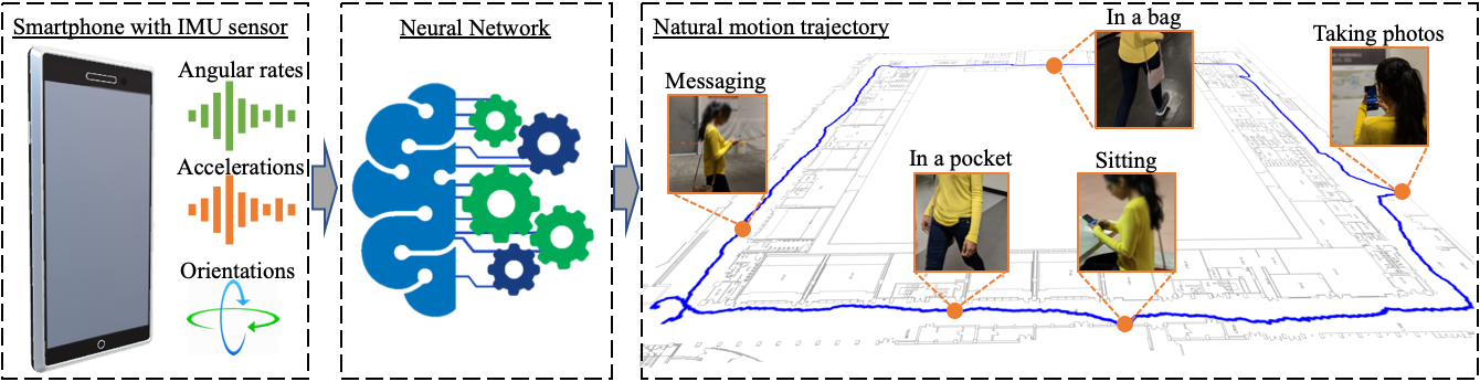
Inertial navigation is the ultimate form of IMU-based navigation, whose task is to estimate positions and orientations of a moving subject only from a sequence of IMU sensor measurements (See Fig. RoNIN: Robust Neural Inertial Navigation in the Wild: Benchmark, Evaluations, and New Methods). Inertial navigation has been a dream technology for academic researchers and industrial engineers, as IMUs 1) are energy-efficient, capable of running 24 hours a day; 2) work anywhere even inside pockets; and 3) are in every smartphone, which everyone carries everyday all the time.
Most existing inertial navigation algorithms require unrealistic constraints that are incompatible with everyday smartphone usage scenarios. For example, an IMU must be attached to a foot to enable the zero speed update heuristic (i.e., a device speed becomes 0 every time a foot touches the ground) [11]. Step counting methods assume that the IMU is rigidly attached to a body and a subject must walk forward so that the motion direction becomes a constant in device coordinate frame [3].
Data-driven approaches have recently made a breakthrough in loosing these constraints [22, 5] where the acquisition of IMU sensor data and ground-truth motion trajectories allows supervised learning of direct motion parameters (e.g., a velocity vector from IMU sensor history). This paper seeks to take data-driven inertial navigation research to the next level via the following three contributions.
The paper provides the largest inertial navigation database consisting of more than 42.7 hours of IMU and ground-truth 3D motion data from 100 human subjects. Our data acquisition protocol allows users to handle smartphones naturally as in real day-to-day activities.
The paper presents novel neural architectures for inertial navigation, making significant improvements for challenging motion cases over the existing best method.
The paper presents extensive qualitative and quantitative evaluations of existing baselines and state-of-the-art methods on the three benchmarks.
We will share the code and data to promote further research in a hope to establish an ultimate anytime anywhere navigation system for everyone’s smartphone.
2 Related Work
We group inertial navigation algorithms into three categories based on their use of priors.
Physics-based (no priors): IMU double integration is a simple idea for inertial navigation. Given the device orientation (e.g., via Kalman filter[12] on IMU signals), one subtracts the gravity from the device acceleration, integrates the residual accelerations once to get velocities, and integrates once more to get positions. Unfortunately, sensor biases explode quickly in the double integration process, and these systems do not work in practice without additional constraints. A foot mounted IMU with zero speed update is probably the most successful example, where the sensor bias can be corrected subject to a constraint that the velocity must become zero whenever a foot touches the ground.
Heuristic priors: Human motions are highly repetitive. Most existing inertial navigation research seeks to find heuristics exploiting such motion regularities. Step counting is a popular approach assuming that 1) An IMU is rigidly attached to a body; 2) The motion direction is fixed with respect to the IMU; and 3) The distance of travel is proportional to the number of foot-steps. The method produces impressive results in a controlled environment where these assumptions are assured. More sophisticated approaches utilize principal component analysis [10] or frequency domain analysis [13] to infer motion directions. However, these heuristic based approaches do not match up with the robustness of emerging data-driven methods [22].
Data-driven priors: Robust IMU double integration (RIDI) was the first data driven Inertial navigation method [22]. RIDI focuses on regressing velocity vectors in a device coordinate frame, while relying on traditional sensor fusion methods to estimate device orientations. RIDI works for complex motion cases such as backward-walking, significantly expanding the operating ranges of the inertial navigation system. IONet is a neural network based approach, which regresses the velocity magnitude and the rate of motion-heading change without relying on external device orientation information [4].
Inertial navigation datasets: RIDI dataset utilized a phone with 3D tracking capability (Lenovo Phab Pro 2) to collect IMU-motion data under four different phone placements (i.e., a hand, a bag, a leg pocket, and a body). The Visual Inertial SLAM produced the ground-truth motion data. The data was collected by 10 human subjects, totalling 2.5 hours. IONet dataset, namely OXIOD used a high precision motion capture system (Vicon) under four different phone placements (i.e., a hand, a bag, a pocket, and a trolley) [5]. The data was collected by five human subjects, totalling 14.7 hours.
The common issue in these datasets is the reliance on a single device for both IMU data and the ground-truth motion acquisition. The phone must have a clean line-of-sight for Visual Inertial SLAM or must be clearly visible for the Vicon system all the time, prohibiting natural phone handling especially for a bag and a leg pocket scenarios. This paper presents a new IMU-motion data acquisition protocol that utilizes two smartphones to overcome these issues.
3 The RoNIN dataset
Scale, diversity and fidelity are the three key factors in building a next-generation inertial navigation database. In comparison to the current largest database OXIOD [5], our dataset boasts
Scale: 42.7 hours of IMU-motion data (2.9 times more than OXIOD) over 276 sequences in 3 buildings,
Diversity: 100 human subjects (20 times more than OXIOD) with three Android devices,222Asus Zenfone AR, Samsung Galaxy S9 and Google Pixel 2 XL, where the first device uses a ICM20602 IMU sensor from InvenSense and the latter two use the same LSM6DSL sensor from STMicro.
Fidelity: subjects handle devices naturally as in real day-to-day activities such as carrying inside a bag, placing deep inside a pocket, or picking up by hand, while walking, sitting or wandering around.
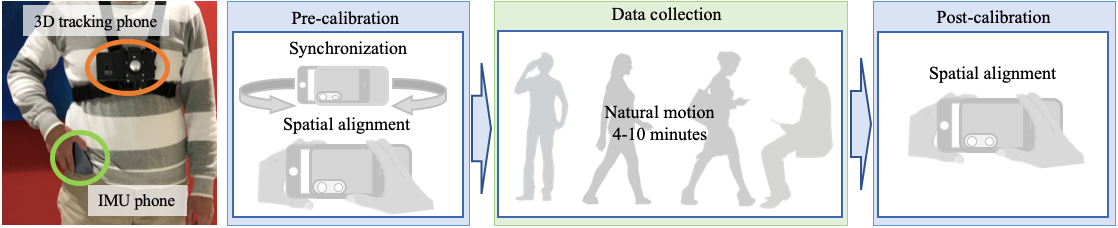
We have developed a two-device data acquisition protocol, where we use a harness to attach a 3D tracking phone (Asus Zenfone AR) to a body and let subjects handle the other phone freely for IMU data collection (See Fig. 2). Besides the benefits of allowing natural body motions and phone handling, this protocol exhibits two important changes to the nature of motion learning tasks.
The positional ground-truth is obtained only for the 3D tracking phone attached to a harness, and our task is to estimate the trajectory of a body instead of the IMU phone.
The data offers a new task of body heading estimation. A standard sensor fusion algorithm works well for the device orientation estimation [18, 15]. However, the body heading is more challenging, because the body orientation differs from the device orientation arbitrarily depending on how one carries a phone. We collect the ground-truth body headings by assuming that they are identical to the headings of the tracking phone with an constant offset introduced by the misalignment of the harness. We ask each subject to walk straight for the first five seconds, then estimate this offset angle as the difference between the average motion heading and the tracking phone’s heading.
We have made great engineering efforts in implementing the data processing pipeline to ensure high-quality sensor data and ground-truth, where we refer the details to the supplementary document. We conducted quantitative assessments of our system and found that our “ground truth” trajectories drift less than 0.3m after 10 minutes of activities. Similarly, the device orientation estimation from Android system API drift less than 20 degrees, while our system further reduces it to less than 10 degrees, which we treat as ground-truth during training. Both IMU sensor data and 3D pose data are recorded at 200Hz. We also record measurements from the magnetometer and the barometer.
We divide the dataset into two groups: 85 subjects in group 1 and the remaining 15 subjects in group 2. Group 1 is further divided into training, validating and testing subsets while group 2 is used to test the generalization capability of the model to unseen human subjects.
4 Robust Neural Inertial Navigation (RoNIN)
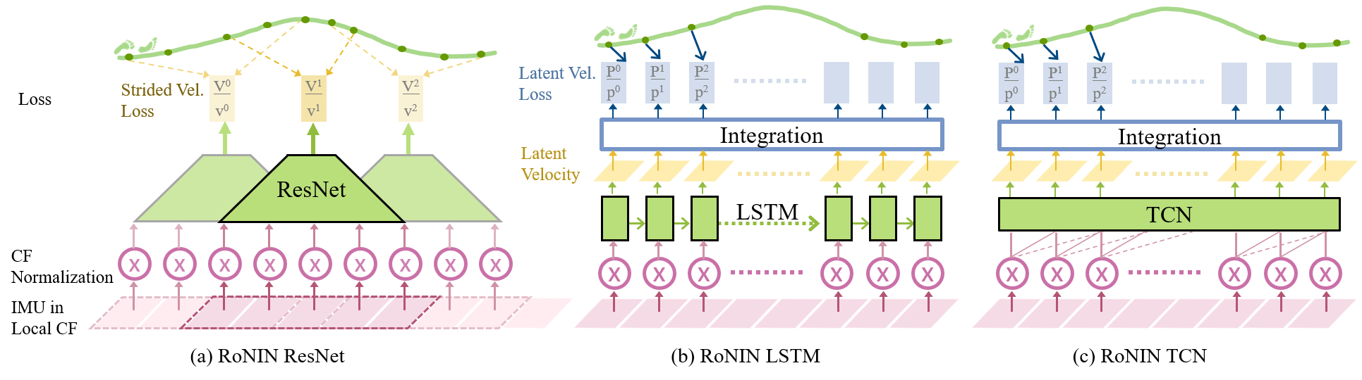
Our neural architecture for inertial navigation, dubbed Robust Neural Inertial Navigation (RoNIN), takes ResNet [8], Long Short Term Memory Network (LSTM) [9], or Temporal Convolutional Network (TCN) [2] as its backbone. RoNIN seeks to regress a velocity vector given an IMU sensor history with two key design priciples: 1) Coordinate frame normalization defining the input and output feature space and 2) Robust velocity losses improving the signal-to-noise-ratio even with noisy regression targets. We now explain the coordinate frame normalization strategy, three backbone neural architectures, and the robust velocity losses. Lastly, the section presents our neural architecture for the body heading regression.
4.1 Coordinate frame normalization
Feature representations, in our case the choice of coordinate frames, have significant impacts on the training. IMU sensor measurements come from moving device coordinate frames, while ground-truth motion trajectories come from a global coordinate frame. RoNIN uses a heading-agnostic coordinate frame to represent both the input IMU and the output velocity data.
Suppose we pick the local device coordinate frame to encode our data. The device coordinate changes every frame, resulting in inconsistent motion representation. For example, target velocities would change depending on how one holds a phone even for exactly the same motions.
RIDI [22] proposed the stabilized IMU coordinate frame, which is obtained from the device coordinate frame by aligning its Y-axis with the negated gravity direction. However, this alignment process has a singularity (ambiguity) when the Y-axis points towards the gravity (e.g., a phone is inside a leg pocket upside-down), making the regression task harder, usually completely fail due to the randomness.
RoNIN uses a heading-agnostic coordinate frame (HACF), that is, any coordinate frame whose Z axis is aligned with gravity. In other words, we can pick any such coordinate frame as long as we keep it consistent throughout the sequence. The coordinate transformation into HACF does not suffer from singularities or discontinuities with proper rotation representation, e.g. with quaternion.
During training, we use a random HACF at each step, which is defined by randomly rotating ground-truth trajectories on the horizontal plane. IMU data is transformed into the same HACF by the device orientation and the same horizontal rotation. The use of device orientations effectively incorporates sensor fusion 333We utilize Android’s game rotation vector as device orientations. into our data-driven system. At test time, we use the coordinate frame defined by system device orientations from Android or iOS, whose Z axis is aligned with gravity.
4.2 Backbone architectures
RoNIN ResNet: We take the 1D version of the standard ResNet-18 architecture [8] and add one fully connected layer with 512 units at the end to regress a 2D vector. At frame , the network takes IMU data from frame to as a tensor and produces a velocity vector at frame . At test time, we make predictions every five frames and integrate them to estimate motion trajectories.
RoNIN LSTM: We use a stacked unidirectional LSTM while enriching its input feature by concatenating the output of a bilinear layer [20]. RoNIN-LSTM has three layers each with 100 units and regresses a 2D vector for each frame, to which we add an additional integration layer to calculate the loss. See Sect. 4.3 for the details of the integration layer.
RoNIN TCN: TCN is a recently proposed CNN architecture, which approximates many-to-many recurrent architectures with dilated causal convolutions. RoNIN TCN has six residual blocks with 16, 32, 64, 128, 72, and 36 channels, respectively, where a convolutional kernel of size 3 leads to the receptive field of 253 frames.
4.3 Robust velocity loss
Defining a velocity for each IMU frame amounts to computing the derivative of low-frequency VI-SLAM poses at much higher frame rate. This makes the ground-truth velocity very noisy. We propose two robust velocity losses that increase the signal-to-noise-ratio for better motion learning.
Latent velocity loss: RoNIN LSTM/TCN regresses a sequence of two dimensional vectors over time. We add an integration layer that sums up the vectors (over 400/253 frames for LSTM/TCN), then define a L2 norm against the ground-truth positional difference over the same frame-window. Note that this loss simply enforces that the sum of per-frame 2D vectors must match the position difference. To our surprise, both LSTM and TCN learn to regress a velocity in this latent layer before the integration, and hence, we name it the latent velocity loss.
Strided velocity loss: For RoNIN ResNet, the network learns to predict positional difference over a stride of 200 frames (i.e., one second), instead of instantaneous velocities. More specifically, we compute MSE loss between the network output at frame and , where is the ground truth position at frame in the global frame.
4.4 RoNIN body heading network
Different from the position regression, the task of heading regression becomes inherently ambiguous when a subject is stationary. Suppose one is sitting still at a chair for 30 seconds. We need to access the IMU sensor data 30 seconds back in time to estimate the body heading, as IMU data have almost zero information after the sitting event. Therefore, we borrow the RoNIN LSTM architecture for the task, which is capable of keeping a long memory.
More precisely, we take the RoNIN LSTM architecture without the integration layer, and let the network predict a vector , which are and values of the body heading angle at each frame. During training, we unroll the network over 1,000 steps for back-propagation. Note that the initial state is ambiguous if the subject is stationary, therefore we only update network parameters when the first frame of the unrolled sequence have velocity magnitude greater than .
We use MSE loss against and values of ground-truth body heading angles. We also add a normalization loss as to guide the network to predict valid trigonometric values.
5 Evaluations: Preliminaries
We implement the proposed architectures using PyTorch and run our experiments using NVIDIA 1080Ti with 12GB GPU memory.
For RoNIN ResNet, we extract one training/validation sample (consisting of 200 frames) every 10 frames. Training samples are randomly shuffled for each epoch. For RoNIN LSTM, we unroll the sequence to 400 steps once per frames, where is a random number between 50 and 150. Unrolled sequences are randomly batched to update network parameters. For RoNIN TCN, we construct one training/validation sample with 400 frames per frames, where is again a random number between 50 and 150.
For RoNIN ResNet (resp. RoNIN LSTM/TCN), we use a batch size of 128 (resp. 72), an initial learning rate of (resp. ), and ADAM optimizer while reducing the learning rate by a factor of 0.1 (resp. 0.75) if the validation loss does not decrease in 10 epochs, where the training typically converges after 100 (resp. 300/200) totalling 10 hours (resp. 40/30 hours). For linear layers we apply dropout with the keep probability 0.5 for RoNIN ResNet and 0.8 for RoNIN LSTM/TCN.
5.1 Competing methods
We conduct qualitative and quantitative evaluations of proposed algorithms on three datasets (RIDI, OXIOD, and RoNIN datasets) with four competing methods:
Naive double integration (NDI): We transform linear accelerations (with gravity subtracted) into the global coordinate frame using device orientations and integrate them twice to get positions. We use Android API (Game Rotation Vector) to obtain the device orientations.
Pedestrian Dead Reckoning (PDR): We utilize a step-counting algorithm [21] to detect foot-steps and move the position along the device heading direction by a predefined distance of per step.
Robust IMU Double Integration (RIDI): We use the official implementation [22]. For RIDI and OXIOD datasets, we train a separate model for each phone placement type. For RoNIN dataset, where phone placement types are mixed, we train one unified model with of RoNIN training data, since their Support Vector Regression does not scale to larger dataset. Hyper-parameters are determined by a simple grid search on the validation set.
IONet: We use our local implementation, as the code is not publicly available. As in RIDI method, we train a unified model on RoNIN dataset, and a separate model for each placement type for RIDI and OXIOD datasets.
5.2 Device orientation handling
PDR, RIDI and RoNIN rely on external device orientation information. For fairness we use the device orientation estimated from IMU for testing. During training, we use the same estimated orientations for RIDI dataset. For OXIOD dataset, we found that the estimated orientations are severely corrupted, 444We believe that this is due to the poor bias calibration and the inappropriate choice of APIs using the magnetic field, which is usually distorted in indoor. and use the ground-truth orientations from Vicon during training. For RoNIN, we use the estimated device orientations if the end-sequence alignment error is below 20 degrees (See Fig. 2), otherwise choose the ground-truth to minimize noise during training.
5.3 Ground-truth alignment
RoNIN estimates trajectories in the global frame and we directly compare against the ground-truth for evaluations. IONet is ambiguous in rotation and we use ICP to align the first 5 seconds of the estimated and ground-truth trajectories before evaluation in their favor. For NDI, PDR, and RIDI, we could align the estimated trajectory based on the device orientation at the first frame. However, a single frame information is often erroneous and we again use the first 5 seconds of the trajectories to align with the ground-truth.
6 Evaluations
We conduct comprehensive evaluations on two tasks: 1) position estimation among five competing methods on three datasets; and 2) body heading estimation by our method on the RoNIN dataset.
| Test subjects | Metric | NDI | PDR | RIDI | IONet | RoNIN | |||
|---|---|---|---|---|---|---|---|---|---|
| ResNset | LSTM | TCN | |||||||
| RIDI Dataset | Seen | ATE | 31.06 | 3.52 | 1.88 | 11.46 | 1.63 | 2.00 | 1.66 |
| RTE | 37.53 | 4.56 | 2.38 | 14.22 | 1.91 | 2.64 | 2.16 | ||
| Unseen | ATE | 32.01 | 1.94 | 1.71 | 12.50 | 1.67 | 2.08 | 1.66 | |
| RTE | 38.04 | 1.81 | 1.79 | 13.38 | 1.62 | 2.10 | 2.26 | ||
| OXIOD Dataset | Seen | ATE | 716.31 | 2.12 | 4.12 | 1.79 | 2.40 | 2.02 | 2.26 |
| RTE | 606.75 | 2.11 | 3.45 | 1.97 | 1.77 | 2.33 | 2.63 | ||
| Unseen | ATE | 1941.41 | 3.26 | 4.50 | 2.63 | 6.71 | 7.12 | 7.76 | |
| RTE | 848.55 | 2.32 | 2.70 | 2.63 | 3.04 | 5.42 | 5.78 | ||
| RoNIN Dataset | Seen | ATE | 675.21 | 29.54 | 17.06 | 31.07 | 3.54 | 4.18 | 4.38 |
| RTE | 169.48 | 21.36 | 17.50 | 24.61 | 2.67 | 2.63 | 2.90 | ||
| Unseen | ATE | 458.06 | 27.67 | 15.66 | 32.03 | 5.14 | 5.32 | 5.70 | |
| RTE | 117.06 | 23.17 | 18.91 | 26.93 | 4.37 | 3.58 | 4.07 | ||
6.1 Position evaluations
We use two standard metrics proposed in [19].
Absolute Trajectory Error (ATE), defined as the Root Mean Squared Error (RMSE) between estimated and ground truth trajectories as a whole.
Relative Trajectory Error (RTE), defined as the average RMSE over a fixed time interval, 1 minute in our evaluations. For sequences shorter than 1 minute, we compute the positional error at the last frame and scale proportionally (e.g., double the number for a sequence of 0.5 minute).
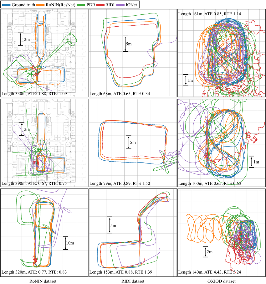
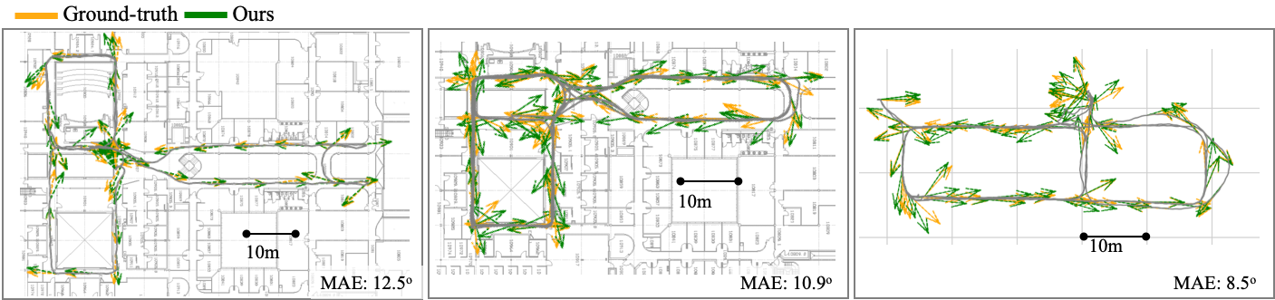
Table 1 is our main result. All three datasets provide two testing sets, one for subjects that are also included in the training set and the other for unseen subjects. We report performance on both sets to evaluate the generalization ability. Figure 4 shows selected visualizations of the reconstructed trajectories against the ground-truth. We show RoNIN ResNet from our methods. Please refer to the supplementary material for more visualizations, including RoNIN LSTM/TCN. We exclude the visualization of NDI, whose trajectories are highly erroneous and would clutter the plots.
Our method outperforms competing approaches on RIDI and RoNIN datasets with significant margins. Most notably, no previous methods can handle natural complex motions presented in our RoNIN dataset. IONet suffers from accumulation errors in the motion heading estimation in the process of integrating the heading angle differences. RoNIN LSTM and TCN perform slightly better than RoNIN ResNet on our dataset, but take 3 to 4 times more time to train.
Both RIDI and RoNIN struggle on the OXIOD dataset despite their easy motions, where even PDR works well. This is simply due to their poor device orientation estimations, which RIDI and RoNIN rely on and assume to be correct. We expect their performance to improve with better bias calibration and the use of compass-free device orientation APIs.
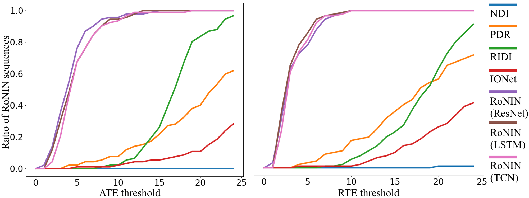
Figure 6 shows the ratios of testing sequences in the RoNIN dataset (Y-axis) under different error thresholds on the two metrics (X-axis). Our methods fail badly for a few sequences, where motions are not represented well in our training set (e.g. a phone in wildly moving handbag).
6.2 Body heading evaluation
We use two metrics for evaluations: 1) Mean Squared Error (MSE) of the representation of the heading; and 2) Mean Angle Error (MAE) of the estimated heading in degrees. We compare against a simple baseline that reports the heading angles from the device orientations (i.e., device z-axis). We can evaluate only the heading difference in this baseline, and hence align the device heading and the ground-truth body heading by first 5 seconds of the sequence.
Table 2 and Figure 5 show the results. We notice that our errors become significantly larger (up to 20 degrees) for a few complex motion cases but are generally less than 12 degrees. The baseline fails because it does not account for the orientation difference between the device and the body.
| Baseline | RoNIN Heading | |||
|---|---|---|---|---|
| Test Subjects | Seen | Unseen | Seen | Unseen |
| MSE | 1.58 | 0.99 | 0.06 | 0.08 |
| MAE (degree) | 90.60 | 89.10 | 13.20 | 15.60 |
6.3 Ablation study
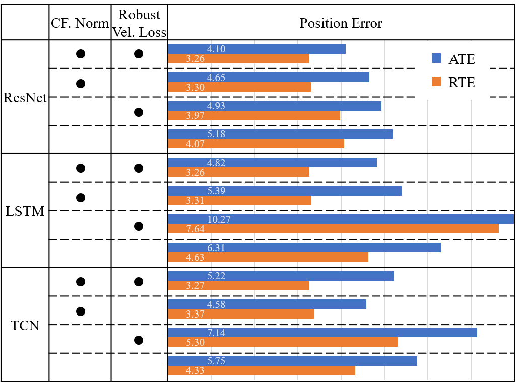
Figure 7 shows the ablation study on the RoNIN dataset, demonstrating the effectiveness of the coordinate frame normalization and the robust velocity loss. We evaluate the changes in the ATE and RTE metrics on the RoNIN test sequences (seen and unseen subjects combined) by turning on and off these two features for the three architectures.
As a baseline without the coordinate frame normalization, we supply the raw IMU sensor measurements as input and the ground-truth velocity in the local device coordinate frame as output. Note that all three dimensions are needed and we rotate predicted velocities to the heading agnostic coordinate frame for position integration. The vertical axis is discarded during evaluations.
As a baseline without the strided velocity loss for RoNIN ResNet, we apply Gaussian smoothing with [22] to reduce the noise of ground-truth velocities, as suggested by RIDI. We use the smoothed instantaneous velocities as the supervision.
As a baseline without the latent velocity loss for RoNIN LSTM/TCN, we directly minimize MSE loss with the ground-truth instantaneous velocities.
Figure 7 demonstrates that the coordinate frame normalization and the robust velocity losses improve ATE and RTE overall, while the former seems to have larger impact. In particular, ATE and RTE shows the lowest errors when both features are combined except for one case, where ATE score of TCN is the second best with a very small margin.
7 Discussions
This paper sets a new foundation for data-driven inertial navigation research by 1) the new benchmark with large and diverse quantity of IMU-motion data as in real day-to-day activities; 2) new neural inertial navigation architectures making significant improvements over challenging motion cases; and 3) qualitative and quantitative evaluations of the current competing methods over the three inertial navigation datasets. The major limitation of our approach comes from the reliance on the device orientation estimations. The performance degrades significantly given data with poor device orientations, which is the main focus of our future work. We will share all our code and data to promote further research towards an ultimate anytime anywhere navigation system for everyone’s smartphone.
8 Acknowledgement
This research is partially supported by National Science Foundation under grant IIS 1618685, NSERC Discovery Grants, NSERC Discovery Grants Program Accelerator Supplements, and DND/NSERC Discovery Grant Supplement. We thank Ao Li for his contributions at an early stage of the project.
References
- [1] Apple. Apple arkit. https://developer.apple.com/arkit/.
- [2] S. Bai, J. Z. Kolter, and V. Koltun. An empirical evaluation of generic convolutional and recurrent networks for sequence modeling. arXiv preprint arXiv:1803.01271, 2018.
- [3] A. Brajdic and R. Harle. Walk detection and step counting on unconstrained smartphones. In Proceedings of the 2013 ACM international joint conference on Pervasive and ubiquitous computing, pages 225–234. ACM, 2013.
- [4] C. Chen, X. Lu, A. Markham, and N. Trigoni. Ionet: Learning to cure the curse of drift in inertial odometry. In Thirty-Second AAAI Conference on Artificial Intelligence, 2018.
- [5] C. Chen, P. Zhao, C. X. Lu, W. Wang, A. Markham, and N. Trigoni. Oxiod: The dataset for deep inertial odometry. arXiv preprint arXiv:1809.07491, 2018.
- [6] C. Forster, L. Carlone, F. Dellaert, and D. Scaramuzza. On-manifold preintegration for real-time visual–inertial odometry. IEEE Transactions on Robotics, 33(1):1–21, 2017.
- [7] Google. Arcore. https://developers.google.com/ar/.
- [8] K. He, X. Zhang, S. Ren, and J. Sun. Deep residual learning for image recognition. In Proceedings of the IEEE conference on computer vision and pattern recognition, pages 770–778, 2016.
- [9] S. Hochreiter and J. Schmidhuber. Long short-term memory. Neural computation, 9(8):1735–1780, 1997.
- [10] J. Janardhanan, G. Dutta, and V. Tripuraneni. Attitude estimation for pedestrian navigation using low cost mems accelerometer in mobile applications, and processing methods, apparatus and systems, Apr. 8 2014. US Patent 8,694,251.
- [11] A. R. Jimenez, F. Seco, C. Prieto, and J. Guevara. A comparison of pedestrian dead-reckoning algorithms using a low-cost mems imu. In 2009 IEEE International Symposium on Intelligent Signal Processing, pages 37–42. IEEE, 2009.
- [12] R. E. Kalman. A new approach to linear filtering and prediction problems. Journal of basic Engineering, 82(1):35–45, 1960.
- [13] M. Kourogi and T. Kurata. A method of pedestrian dead reckoning for smartphones using frequency domain analysis on patterns of acceleration and angular velocity. In Position, Location and Navigation Symposium-PLANS 2014, 2014 IEEE/ION, pages 164–168. IEEE, 2014.
- [14] S. Leutenegger, S. Lynen, M. Bosse, R. Siegwart, and P. Furgale. Keyframe-based visual–inertial odometry using nonlinear optimization. The International Journal of Robotics Research, 34(3):314–334, 2015.
- [15] S. Madgwick. An efficient orientation filter for inertial and inertial/magnetic sensor arrays. Report x-io and University of Bristol (UK), 25:113–118, 2010.
- [16] Microsoft. Hololens. https://www.microsoft.com/microsoft-hololens/en-us.
- [17] R. Mur-Artal and J. D. Tardós. Visual-inertial monocular slam with map reuse. IEEE Robotics and Automation Letters, 2(2):796–803, 2017.
- [18] A. M. Sabatini. Quaternion-based extended kalman filter for determining orientation by inertial and magnetic sensing. IEEE Transactions on Biomedical Engineering, 53(7):1346–1356, 2006.
- [19] J. Sturm, N. Engelhard, F. Endres, W. Burgard, and D. Cremers. A benchmark for the evaluation of rgb-d slam systems. In 2012 IEEE/RSJ International Conference on Intelligent Robots and Systems, pages 573–580. IEEE, 2012.
- [20] J. B. Tenenbaum and W. T. Freeman. Separating style and content with bilinear models. Neural computation, 12(6):1247–1283, 2000.
- [21] Q. Tian, Z. Salcic, I. Kevin, K. Wang, and Y. Pan. An enhanced pedestrian dead reckoning approach for pedestrian tracking using smartphones. In Intelligent Sensors, Sensor Networks and Information Processing (ISSNIP), 2015 IEEE Tenth International Conference on, pages 1–6. IEEE, 2015.
- [22] H. Yan, Q. Shan, and Y. Furukawa. Ridi: Robust imu double integration. In Proceedings of the European Conference on Computer Vision (ECCV), pages 621–636, 2018.
See pages 1 of supplement See pages 2 of supplement See pages 3 of supplement See pages 4 of supplement See pages 5 of supplement