Spectral singularity enhances transverse spin
Abstract
We study the transverse spin and the Belinfante spin momentum in a gain-loss balanced waveguide, known to be one of the first and most studied examples of -symmetric systems. Such a guide supports the spectral singularities leading to infinite scattering amplitudes for both reflection and transmission. We show that near the spectral singularity there can be dramatic enhancement of the transverse spin and the transverse spin momentum. Note that these exotic spin and spin momentum have recently been observed experimentally despite having tiny magnitudes, making it worthy to explore ways and means to enhance these fundamentally important elusive quantities.
keywords:
Transverse spin, Belinfante spin momentum, -symmetric waveguide.1 Introduction
In recent years there has been a great deal of interest in the angular momentum carried by light [1, 2, 3]. It is now well understood that in addition to usual longitudinal angular momentum structured light can possess an extraordinary transverse spin angular momentum (SAM) [4, 5, 6, 7, 8, 9, 10, 11]. While the transverse SAM is helicity independent, the transverse momentum can be sensitive to the helicity, opening up new possibilities for spin optics [4, 5, 6]. The existence of such nonstandard spin-momentum was first discussed by Belinfante in a seminal field theoretical paper in 1940 [12]. The spin momentum discovered by Belinfante was considered to be virtual or elusive, since it has no effect on dipolar particles (in the sense of transferring energy or exerting optical pressure). In contrast, the usual canonical momentum exerts the radiation pressure leading to easily observable experimental effects [13, 4]. Despite the tiny effect produced by this extraordinary spin momentum, it has now been observed experimentally [14, 9, 15]. There have been studies pointing to the novel use in spin locking and mapping fields in nano-optical systems [16, 17, 18, 19, 20]. The generic feature responsible for the extraordinary spin and spin-momentum is the existence of a longitudinal component of the field in structured light [3, 4]. Note that the conventional featureless plane waves do not have any such components and thus cannot exhibit the unusual effects. In contrast, strongly focused beams [14] or evanescent waves associated with total internal reflection or surface excitations of plasmonic systems can have very strong longitudinal components of field [4, 21]. The other essential aspect is the finite phase difference between longitudinal and transverse components of the field vector resulting in a ‘polarization ellipse’ in the plane of incidence [16]. The rotating tip of the field vector in time in the plane of incidence results on transverse spin. All these features have been discussed at great length in several recent reviews [3, 11, 22, 23]. One of the major directions that emerge is how to enhance the tiny Belinfante momentum. Strong coupling mediated dispersion management was proposed to be one of the possible ways [24] to enhance the transverse spin. Coherent perfect absorption [25, 26] was shown to further enhance the effects [27]. Only passive systems were probed. To the best of our knowledge, there are no studies on transverse spin and spin momentum in optical systems with gain, keeping this in view in this paper we propose a gain-loss balanced -symmetric waveguide for enhancing the transverse spin and spin-momentum. The proposed system serves several goals. Firstly, the wave-guiding geometry ensures the existence of a longitudinal field component with the necessary phase lag as compared to the transverse component. Second and most importantly, a properly tuned -symmetric guide can have a spectral singularity, leading to blown up scattering amplitudes for both reflection and transmission. Though infinities are not encountered in realistic nonlinear systems [28, 29], there is always a significant field enhancement. We show that the resonances of ‘null’ width of the -symmetric system can lead to dramatic enhancement of the transverse spin. Recall that the interest in the -symmetric systems was initially motivated by mathematical and fundamental aspects that concerned real spectra of non-Hermitian systems [30]. Since then a great deal of research has been carried out on photonic systems [31, 32]. There are now several studies highlighting few practical applications in photonics. A very recent study exploits the highly dispersive properties of such systems for stopping and storing light [33]. However, -symmetry has not been exploited so far in the context of the elusive Belinfante’s spin-momentum.
2 Formulation of the problem
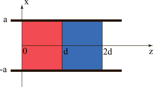
Consider the balanced waveguide of width having equal sections of gain and loss media each of length (see Fig. 1). The guide has an infinite extent along so that we can ignore the variations along (). Outside the gain-loss region the guide is filled with a dielectric with dielectric constant , while the dielectric function of the gain /loss medium is given by
| (1) |
where and are the plasma and the resonance frequencies, respectively, and gives the decay constant. The subscript 1 (2) refer to the gain (loss) medium with (). Throughout the text, permittivity and relative permittivity are denoted as and while permeability and relative permeability are denoted as and , respectively.
Let the guide be excited from the left by a TM mode with the only non-vanishing magnetic field component along . As mentioned in the Introduction, such a guide satisfies the necessary conditions of -symmetry, since Eq. (1) fulfills the requirement for the system-wide variation of the dielectric function near . In what follows we examine the electric and magnetic field in each region and outline the procedure to arrive at the spin and spin momentum densities.
2.1 Fields, spin and spin momentum density
We follow electric-magnetic democracy and use scaled fields and since they have the same dimension [13, 2]. The presence of a waveguide restricts the -component of the wavevector as . The only non-vanishing component of the magnetic field in different regions can be expressed as follows
| (2) | ||||
| (3) | ||||
| (4) | ||||
| (5) |
In Eqs.(2) – (5), subscripts 0 and t refer to the medium of incidence and transmittance, while 1 (2) points to the gain (loss) medium occupying (). and , are the and components of the wave vector, respectively. Using Eqs. (2) – (5) one can easily calculate the corresponding electric fields. For example,
| (6) | ||||
| (7) |
where we have introduced the following abbreviated notations
| (8) | ||||
| (9) |
Here, , () and . Demanding the continuity of the tangential fields across the interfaces (i.e., ), one can calculate the amplitudes in all the media. For example,
| (10) |
where are the characteristic matrices of gain and loss media, respectively [2].
As mentioned in the Introduction, a great deal of research has been carried out on the structure of the Poynting current and optical momentum density. it is now clear that the momentum density in a monochromatic optical field can be decomposed into two parts, namely, the orbital (canonical) momentum and ‘intrinsic’ spin momentum as follows [3, 13, 4, 5, 22, 34, 35]
| (11) | ||||
| (12) | ||||
| (13) |
where is the spin density. Since, has a single component, it will not contribute to the spin density. Simplifying Eq. (13), we get
| (14) |
Substituting Eqs. (6) and (7) in Eqs. (12) and (13), we get
| (15) | ||||
| (16) | ||||
| (17) |
2.2 Spectral singularity and its effect on the spin density and spin momentum density
From Eq.(10), it is straight forward to define the amplitude (intensity) reflection () and transmission () coefficients, respectively, as follows
| (18) |
A close inspection of Eq. 18 reveals that both and have a common denominator and the dispersion relation for the modes is given by [2]
| (19) |
where are the elements of the total characteristics matrix. The dispersion relation has a complex root in general. The real part of the root of this equation gives the location of the resonance, while the imaginary part embodies the losses of the mode. A spectral singularity corresponds to a resonance of vanishing width rendering the root of dispersion relation on the real axis with . This in turn implies that as a function of real must be zero at the spectral singularity. In the next section we reproduce some of the well known results on spectral singularity in the context of our system and carry forward the calculations for extracting the spin momentum and spin densities. We highlight the existence of the elusive and unusual transverse (perpendicular to the direction of the waveguide axis) components of both these quantities. We show that the spectral singularity can lead to dramatic enhancements of both these extraordinary features.
3 Numerical results and discussions
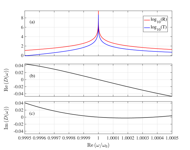
In what follows we present the numerical results pertaining to the balanced gain/loss guide. We start with the well known feature of the spectral singularity for such guides [36, 37]. The spectral singularity for both and along with the real and imaginary parts of are shown in Fig. 2 (a), (b) and (c), respectively. The singularities occur at and for very specific values of system parameters. Note that the response given by Eq.1 is PT-symmetric only at . As discussed in [37] the singularities can be labeled by an integer. We show one of such resonances in Fig 2a for and for , . Henceforth we will label the parameters corresponding to the singularity by subscript 0. As can be seen from Fig. 2a, both and blow up as a consequence of the vanishing width resonance. The plot of as a function of real confirms that. Indeed, the vanishing of both real and imaginary parts of for real at the spectral singularity confines the root of the dispersion relation Eq.19 on the real axis. It is clear that such a root points to a resonance of infinitely narrow width.
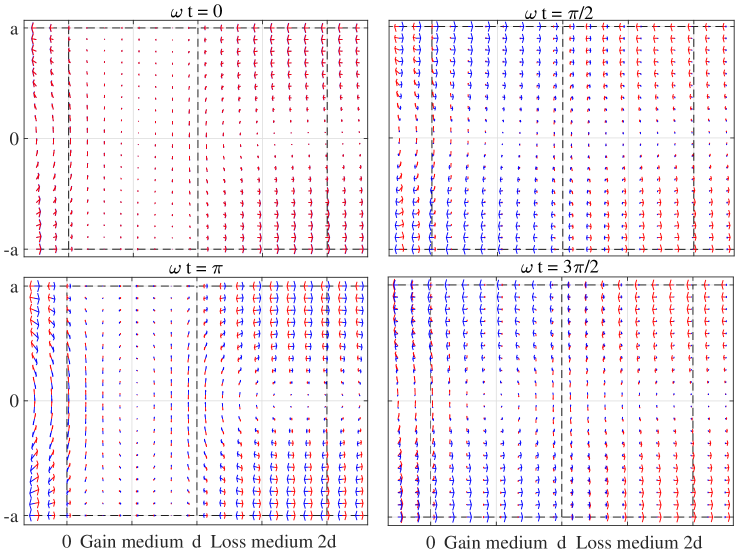
It is clear from Eqs.14 and 15 that the spin density has only one non-vanishing component along y axis due to the TM character of the waveguide mode. We use Eq.15 to calculate the spin density for both the resonant and off-resonant cases. Recall that for the typical parameters used in our system one of the spectral singularities occurs for m, m and . Rotation of the field vector has been identified as the source of transverse spin and spin momentum [24, 4]. Analogous circulation is shown in Fig.3, where the snap shots of the electric field vector is plotted at different times, namely, at . A comparison of these panels clearly reveal the rotation of the electric field vector in the plane of incidence ( plane). In fact, this circulation leads to the transverse spin along the direction in full conformity with the earlier results [4, 24].
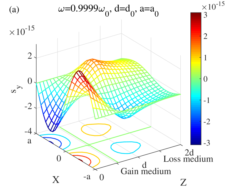
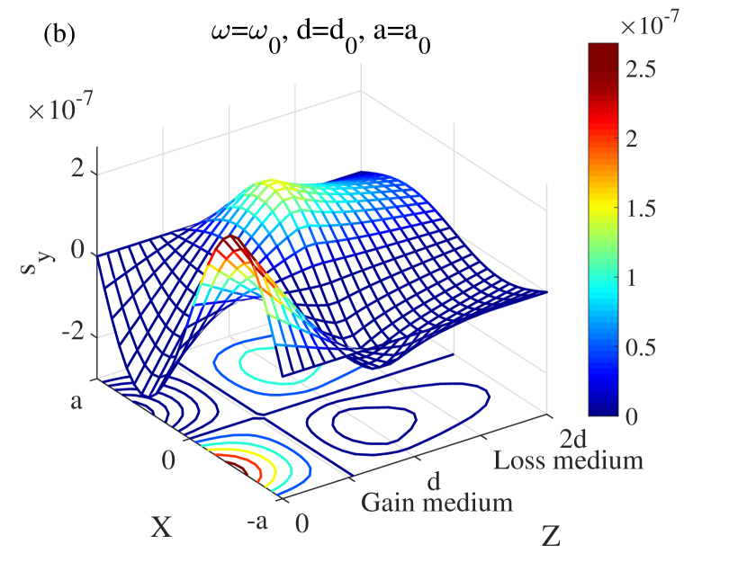
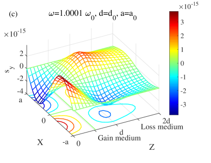
Next we calculate the transverse spin density using Eq.15. The results are shown in Figs. 4(a), (b) and (c) for both off-resonant and on-resonant cases. In each of these figures we have shown the surface plots of along with the corresponding contour profiles over the whole guiding region. For the off-resonant case we have allowed to be away from unity, while the other parameters like and ware taken to be same as corresponding to the resonant values. A comparison of these figures (vertical axis) clearly exposes the role of the spectral singularity in the enhancement of the transverse spin. Moreover, the distribution is mainly governed by the same for the fields due to the guided fundamental mode in the active guide.
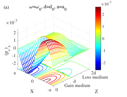

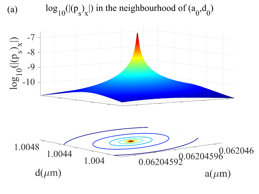
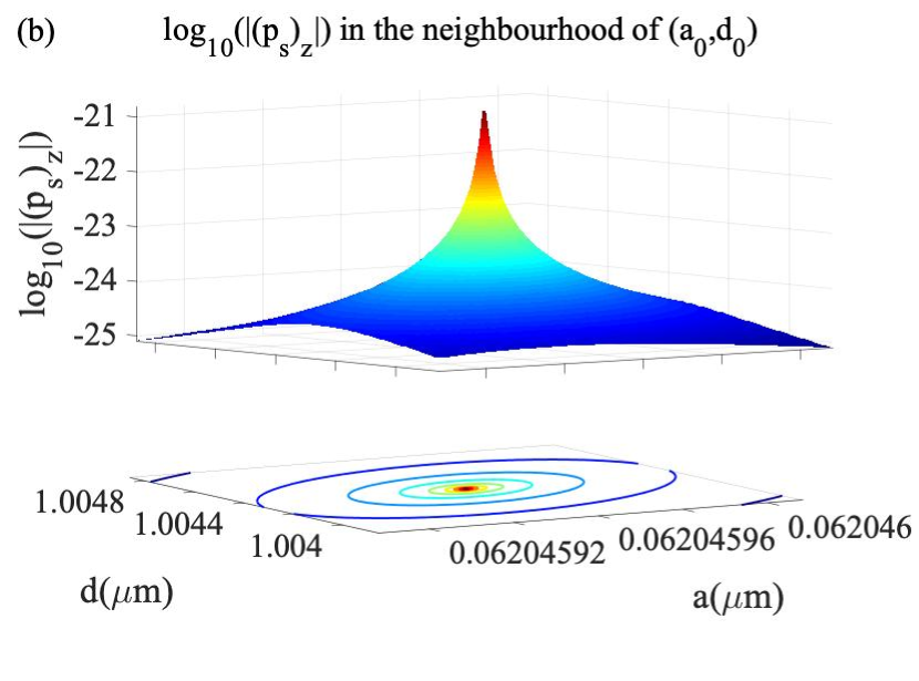
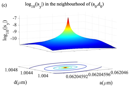
We next took at the dependence of the spin density on the system parameters. In standard scenarios of the origin of transverse spin in structured light there are contributions from a helicity dependent term as in the case with the evanescent waves. In fact this dependence is responsible for the spin locking phenomenon, which leads to the helicity dependent control of the transverse spin-momentum. In our case because of the linearly polarized character of the propagating modes, there is no helicity dependent contribution. However, because of the inhomogeneity of the medium (along ), there are both forward and backward propagating waves. The resulting dependence leads to the transverse component of spin and the component of the Belinfante spin momentum. Note that in standard scenario with evanescent waves, in absence of helicity, the spin momentum density is purely longitudinal. In Fig.5, we show the variation of and components of the spin momentum across the waveguide at the spectral singularity. It is clear that maximum/minimum values of the transverse and longitudinal components of the spin momentum is encountered at the input plane . In Fig.6, we show the logarithm of , and at as a function of the waveguide parameters and . It is observed that as and , an enhancement of the transverse spin is achieved.
4 Conclusion
In conclusion, we have studied a -symmetric gain-loss balanced waveguide and exploited its null-width resonance to enhance the transverse spin and the transverse spin momentum. It was shown that such a system has distinctive features as compared to the widely studied systems with evanescent waves. The transverse spin momentum was shown to have a component normal to the waveguide bounding planes. Our results clearly show the promises of active systems to enhance the elusive Belinfante spin momentum.
References
- [1] L. Allen, S. M. Barnett, M. J. Padgett, Optical angular momentum, IoP Publishing, 2003.
- [2] S. Dutta Gupta, N. Ghosh, A. Banerjee, Wave Optics: Basic Concepts and Contemporary Trends, CRC Press, 2015.
- [3] K. Y. Bliokh, F. Nori, Transverse and longitudinal angular momenta of light, Phys. Rep. 592 (2015) 1–38. doi:10.1016/j.physrep.2015.06.003.
- [4] K. Y. Bliokh, A. Y. Bekshaev, F. Nori, Extraordinary momentum and spin in evanescent waves, Nat Commun 5 (2014). doi:10.1038/ncomms4300.
- [5] A. Aiello, P. Banzer, M. Neugebauer, G. Leuchs, From transverse angular momentum to photonic wheels, Nat. Photonics 9 (12) (2015) 789–795. doi:10.1038/nphoton.2015.203.
-
[6]
A. Y. Bekshaev, K. Y. Bliokh, F. Nori,
Transverse spin and
momentum in two-wave interference, Phys. Rev. X 5 (2015) 011039.
doi:10.1103/PhysRevX.5.011039.
URL http://link.aps.org/doi/10.1103/PhysRevX.5.011039 - [7] T. Bauer, M. Neugebauer, G. Leuchs, P. Banzer, Optical polarization möbius strips and points of purely transverse spin density, Phys. Rev. Lett. 117 (1) (jun 2016). doi:10.1103/physrevlett.117.013601.
- [8] D. O Connor, P. Ginzburg, F. J. Rodriguez-Fortuno, G. A. Wurtz, A. V. Zayats, Spin-orbit coupling in surface plasmon scattering by nanostructures, Nature Communications 5 (11 2014).
- [9] M. Neugebauer, T. Bauer, A. Aiello, P. Banzer, Measuring the transverse spin density of light, Phys. Rev. Lett. 114 (6) (feb 2015). doi:10.1103/physrevlett.114.063901.
- [10] A. Aiello, P. Banzer, The ubiquitous photonic wheel, Journal of Optics 18 (8) (2016) 085605.
- [11] S. Saha, N. Ghosh, S. Dutta Gupta, Transverse spin and transverse momentum in structured optical fields (2019) 1–32doi:10.1002/3527600434.eap818.
-
[12]
F. Belinfante,
On
the current and the density of the electric charge, the energy, the linear
momentum and the angular momentum of arbitrary fields, Physica 7 (5) (1940)
449 – 474.
doi:http://dx.doi.org/10.1016/S0031-8914(40)90091-X.
URL http://www.sciencedirect.com/science/article/pii/S003189144090091X - [13] M. V. Berry, Optical currents, Journal of Optics A: Pure and Applied Optics 11 (August 2009). doi:10.1088/1464-4258/11/9/094001.
- [14] P. Banzer, M. Neugebauer, A. Aiello, C. Marquardt, N. Lindlein, T. Bauer, G. Leuchs, The photonic wheel - demonstration of a state of light with purely transverse angular momentum, Journal of the European Optical Society: Rapid Publications 8 (may 2013). doi:10.2971/jeos.2013.13032.
- [15] M. Antognozzi, C. R. Bermingham, R. L. Harniman, S. Simpson, J. Senior, R. Hayward, H. Hoerber, M. R. Dennis, A. Y. Bekshaev, K. Y. Bliokh, F. Nori, Direct measurements of the extraordinary optical momentum and transverse spin-dependent force using a nano-cantilever, Nat. Phys. 12 (8) (2016) 731–735.
-
[16]
K. Y. Bliokh, D. Smirnova, F. Nori,
Quantum spin hall
effect of light, Science 348 (6242) (2015) 1448–1451.
arXiv:http://science.sciencemag.org/content/348/6242/1448.full.pdf.
URL http://science.sciencemag.org/content/348/6242/1448 - [17] T. Van Mechelen, Z. Jacob, Universal spin-momentum locking of evanescent waves, Optica 3 (2) (2016) 118–126.
- [18] F. Kalhor, T. Thundat, Z. Jacob, Universal spin-momentum locked optical forces, Applied Physics Letters 108 (6) (2016) 061102.
- [19] A. P. Yang, L. P. Du, F. F. Meng, X. C. Yuan, Optical transverse spin coupling through a plasmonic nanoparticle for particle-identification and field-mapping, Nanoscale 10 (19) (2018) 9286–9291. doi:10.1039/c8nr01618f.
- [20] D. Garoli, P. Zilio, F. De Angelis, Y. Gorodetski, Helicity locking of chiral light emitted from a plasmonic nanotaper, Nanoscale 9 (21) (2017) 6965–6969.
-
[21]
K. Y. Bliokh, F. Nori,
Transverse spin of
a surface polariton, Phys. Rev. A 85 (2012) 061801.
doi:10.1103/PhysRevA.85.061801.
URL http://link.aps.org/doi/10.1103/PhysRevA.85.061801 - [22] A. Bekshaev, K. Y. Bliokh, M. Soskin, Internal flows and energy circulation in light beams, Journal of Optics 13 (5) (2011) 053001.
- [23] A. Y. Bekshaev, K. Y. Bliokh, Spin and momentum of the light fields in inhomogeneous dispersive media with application to surface plasmon-polariton waves, Ukrainian Journal of Physical Optics 19 (1) (2018) 33–48.
- [24] S. Saha, A. K. Singh, N. Ghosh, S. D. Gupta, Effects of mode mixing and avoided crossings on the transverse spin in a metal-dielectic-metal sphere, Journal of Optics 20 (2) (2018) 025402. doi:10.1088/2040-8986/aaa077.
- [25] W. Wan, Y. D. Chong, H. N. L. Ge, A. D. Stone, H. Cao, Time-reversed lasing and interferometric control of absorption, Science 331 (2011) 889–892.
-
[26]
S. Deb, S. D. Gupta, J. Banerji, S. D. Gupta,
Critical coupling at
oblique incidence, Journal of Optics A: Pure and Applied Optics 9 (7) (2007)
555–559.
doi:10.1088/1464-4258/9/7/001.
URL https://doi.org/10.1088%2F1464-4258%2F9%2F7%2F001 - [27] S. Mukherjee, S. D. Gupta, Coherent perfect absorption mediated enhancement of transverse spin in a gap plasmon guide, Eur. Phys. J. Appl. Phys. 76 (3) (2016) 30001. doi:10.1051/epjap/2016160330.
-
[28]
X. Liu, S. D. Gupta, G. S. Agarwal,
Regularization of
the spectral singularity in -symmetric systems by all-order
nonlinearities: Nonreciprocity and optical isolation, Phys. Rev. A 89 (2014)
013824.
doi:10.1103/PhysRevA.89.013824.
URL https://link.aps.org/doi/10.1103/PhysRevA.89.013824 -
[29]
K. N. Reddy, S. D. Gupta,
Cavity-controlled
spectral singularity, Opt. Lett. 39 (15) (2014) 4595–4598.
doi:10.1364/OL.39.004595.
URL http://ol.osa.org/abstract.cfm?URI=ol-39-15-4595 -
[30]
C. M. Bender, S. Boettcher,
Real spectra in
non-hermitian hamiltonians having pt symmetry, Phys. Rev. Lett. 80 (1998)
5243–5246.
doi:10.1103/PhysRevLett.80.5243.
URL https://link.aps.org/doi/10.1103/PhysRevLett.80.5243 - [31] H. Zhao, L. Feng, Parity-time symmetric photonics, National Science Review 5 (2) (2018) 183–199. doi:10.1093/nsr/nwy011.
- [32] H. Schomerus, From scattering theory to complex wave dynamics in non-hermitian pt-symmetric resonators, Philosophical Transactions of the Royal Society A: Mathematical, Physical and Engineering Sciences 371 (1989) (2013) 20120194. doi:10.1098/rsta.2012.0194.
-
[33]
T. Goldzak, A. A. Mailybaev, N. Moiseyev,
Light stops at
exceptional points, Phys. Rev. Lett. 120 (2018) 013901.
doi:10.1103/PhysRevLett.120.013901.
URL https://link.aps.org/doi/10.1103/PhysRevLett.120.013901 - [34] A. Y. Bekshaev, M. Soskin, Transverse energy flows in vectorial fields of paraxial beams with singularities, Optics communications 271 (2) (2007) 332–348.
- [35] A. Aiello, M. V. Berry, Note on the helicity decomposition of spin and orbital optical currents, Journal of Optics 17 (2015) 062001. doi:10.1088/2040-8978/17/6/062001.
-
[36]
A. Ruschhaupt, F. Delgado, J. G. Muga,
Physical
realization of -symmetric potential scattering in a planar slab waveguide,
Journal of Physics A: Mathematical and General 38 (9) (2005) L171–L176.
doi:10.1088/0305-4470/38/9/l03.
URL https://doi.org/10.1088%2F0305-4470%2F38%2F9%2Fl03 -
[37]
A. Mostafazadeh,
Spectral
singularities of complex scattering potentials and infinite reflection and
transmission coefficients at real energies, Phys. Rev. Lett. 102 (2009)
220402.
doi:10.1103/PhysRevLett.102.220402.
URL https://link.aps.org/doi/10.1103/PhysRevLett.102.220402