RF design of APEX2 two-cell continuous-wave normal conducting photoelectron gun cavity based on multi-objective genetic algorithm
Abstract
High brightness, high repetition rate electron beams are key components for optimizing the performance of next generation scientific instruments, such as MHz-class X-ray Free Electron Laser (XFEL) and Ultra-fast Electron Diffraction/Microscopy (UED/UEM). In the Advanced Photo-injector EXperiment (APEX) at Berkeley Lab, a photoelectron gun based on a normal conducting re-entrant RF cavity, has been proven to be a feasible solution to provide high brightness, high repetition rate electron beam for both XFEL and UED/UEM. Based on the success of APEX, a new electron gun system, named APEX2, has been under development to further improve the electron beam brightness. For APEX2, we have designed a new two-cell photoelectron gun and achieved a significant increase on the cathode launching field and the beam exit energy. For a fixed charge per bunch, these improvements will allow for the emittance reduction and hence to an incresed beam brightness. The design of APEX2 gun cavity is a complex problem with multiple design goals and restrictions, some even competing each other. For a systematic and comprehensive search for the optmized cavity geometry, we have developed and implemented a novel optimization method based on the Multi-Objective Genetic Algorithm (MOGA).
keywords:
photoelectron RF gun , RF cavity design , multi-objective genetic algorithm1 Introduction
The high brightness, high repetition rate electron beams are key components for several scientific applications, such as X-ray Free Electron Laser (XFEL) [1, 2] and Ultra-fast Electron Diffraction/Microscopy (UEM/UEM) [3] when MHz-class repetition rates are required. Different types of electron guns have been under development for decades, such as the DC gun [4], the normal conducting RF gun [5] and the superconducting RF gun [6], each with its own advantages and challenges. In the Advanced Photo-injector EXperiment (APEX) at Lawrence Berkeley National Laboratory (LBNL), a photoelectron gun based on a normal conducting re-entrant RF cavity operated at Very-High-Frequency (VHF) (1/7th of ), has been designed, manufactured and commissioned [7]. APEX has successfully achieved the emittance requirements for the high brightness, high repetition rate XFEL and demonstrated stable and reliable operations required for a user facility. An electron injector almost identical with APEX has been built and delivered by LBNL as the injector for the Linac Coherent Light Source II (LCLS-II).
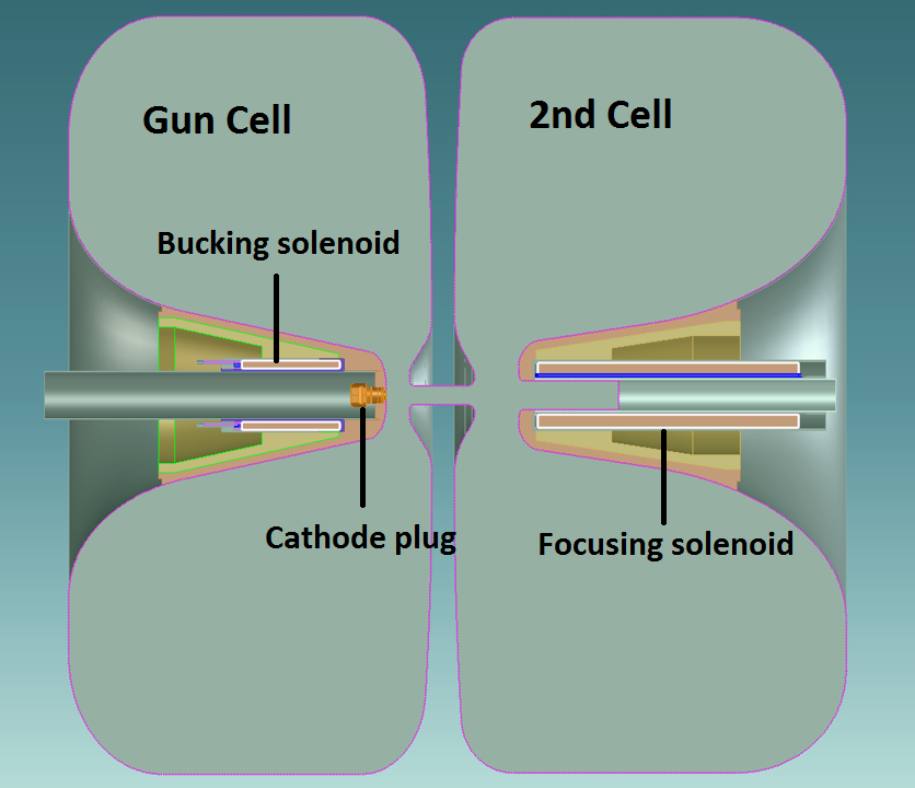
The advance of XFEL and UED/UEM requires ever-increasing brightness for electron sources. Based on the success of APEX, a new project named APEX2 [8] has been initiated at LBNL. APEX2 aims at further extending the performance of normal conducting gun technology by increasing both the cathode launching field and the output energy . A two-cell (1/8th of ) cavity with re-entrant structure similar to APEX was chosen as the design baseline for APEX2. The first cell, named the gun cell, provides high and the initial acceleration for the electron beam. The following cell, named the 2nd cell, carries out further acceleration for the beam.
The requirements on the significant increase for both and , along with constraints from power considerations, engineering feasibility and beam dynamics requirements, impose considerable challenges on the APEX2 cavity RF design. A novel method based on Multi-Object Genetic Algorithm (MOGA) [9] has been developed and applied to APEX2 design. Integrating the MOGA algorithm, the numerical electromagnetic () field solver, and the parallel computing, this method becomes a useful tool for cavity geometry optimization.
The paper is organized as follows. First we describe the novel RF cavity design method based on MOGA. Then we present the RF design of the two-cell gun cavity obtained by this new method. The general properties of the re-entrant VHF gun, a preliminary design of an alternative (1/6th of ) VHF gun, and plans for the future development of the MOGA-based cavity design method are presented in the DISCUSSION section.
2 RF cavity design based on MOGA
Most real-world engineering problems involve simultaneously optimizing multi-objectives where considerations of trade-offs are important. In recent decades, Genetic Algorithm [10] (GA), which is inspired by the evolutionary theory “survival of the fittest”, has became one of the primary tools to solve real-world multi-objective problems. For particle accelerators, MOGA has already been widely applied in the lattice design for photoinjector [11], storage rings [12, 13] and linear accelerators [14, 15] (LINAC).
The idea of implementing GA into RF cavity geometry design was first proposed in 90s [16] but without much follow-up for almost two decades. In recent years, with the advance of both GA algorithms and computation capability, as well as the ever-increasing demand on the cavity performance, more efforts have been invested into this approach[17, 18, 19]. In the conventional design method, the designer starts with an overall cavity shape and defines the geometric variables. During the optimization, the cavity geometry is modified by changing one or a few geometric variables at a time. All the variables are scanned iteratively in a “trail-and-error” approach until a satisfying result is achieved. This method heavily relies on the designer’s experience and judgment. The pre-defined shape where the searching process starts can be over-constrained that potentially better solutions are left out. For complicated geometry with dozens of geometric variables, the scanning process can become tedious. When there are competing optimization goals, the rationale to choose one design over the other is not straightforward. By implementing MOGA into RF cavity design, we aim to establish a quantitatively-defined optimization method with more efficient algorithm and more thorough searching process that can lead to better cavity solution not easily achievable by the conventional method. In what follows we describe in detail this MOGA-based cavity design method.
2.1 Parameterizing Cavity Geometry
Assuming a perfectly conducting cavity surface, the cavity field is determined by its geometry which sets the boundary condition for the Maxwell’s equations. The cavity geometry is described by a geometry vector , where the represent the geometric parameters such as segment lenghts, angles, radius of the arcs, etc.. Cavity optimization is carried out by finding a geometry that provides the most desired eigenmode solution.
Critical aspects of the method reside in the definition of and in choosing the proper scanning range for each . They determine how flexible we can vary the cavity geometry during the optimization and how much the computation cost will be.
2.2 Solving Cavity EM Field
Once the cavity geometry is given, we can calculate the cavity eigenmodes and the corresponding RF properties. Except for a few cases that can be calculated analytically, most cavities’ fields are solved numerically with software such as CST [20], ANSYS [21], COMSOL [22] and ACE3P [23]. In this paper, we use the 2D solver SUPERFISH [24] for its fast speed and built-in post-processing functions. The cavity geometry is translated into an input file for SUPERFISH. Then the relevant RF properties are extracted from the SUPERFISH output. Both relevant geometry parameters and RF properties constitute the figure of merit vector for the cavity , where the represent the cavity frequency , cathode launching field , cavity radius , etc..
2.3 Implementing MOGA
As a multi-objective optimization problem, a cavity RF design can be formatted into finding a geometries that
| (1) |
where the objective vector represents the design goals and the constraint vector represents the restrictions, both derived from cavity’s figure of merit vector . and are respectively the lower and upper limits of the cavity geometry variables . The optimization process results in a group of geometries which are non-dominant [25] over each other. They are called Pareto-optimal solutions and together they make up the Pareto front in the objective phase space. A final geometry is chosen from the Pareto front based on further considerations.
Being a population based approach, GA is well suited to solve multi-objective optimization problem. Many MOGA algorithms have been developed and implemented in different applications. In this paper we use Non-dominant Sorting Genetic Algorithm II (NSGA-II) [26] for its well-tested performance and high efficiency. The detail of the cavity optimization process is described as followsing:
-
1.
Randomly generate the initial set of cavity geometries .
-
2.
Calculate the relavent properties of each geometry by SUPERFISH .
-
3.
Assign ranks and crowd distance to each geometry based on the design goals and restrictions , where and .
-
4.
Produce new geometries from current ones by selection, crossover and mutation: .
-
5.
Calculate the relevant properties of new cavity geometries by SUPERFISH .
-
6.
Sort based on design goals and restrictions by fast-non-dominated-sort, where and .
-
7.
Select new generation of geometries from combined .
-
8.
Go back to Step 2, replace , keep going until reaching targeted generation.
MOGA is naturally suitable for parallel computing. We parallelized the program with Multiple Passage Interface and carried out the computation on a 12-core local Windows workstation. For a population of 720, it takes about 48 hours to finish the calculation of 200 generations.
3 RF design of APEX2 two-cell 162.5 MHz gun cavity
A two-cell cavity is chosen as the baseline for APEX2. The choice of the frequency allows compatibility with other frequencies commonly used in LINAC cavities ( i.e. and for XFEL). Compared to APEX (), the lower frequency also helps reduce the surface resistance and therefore the power density on the cavity inner surfaces. With high , the gun cell generates high current, high brightness electron beam while providing an output energy similar to the APEX gun. The 2nd cell provides further acceleration up to . Both cells are of re-entrant structure similar to APEX. The RF coupling between the two cells is negligible, so they can be powered and tuned separately.
The RF design is intentionally kept similar to the APEX gun, which has already demonstrated several key operating parameters. The new RF field profile of the APEX2 gun has been applied to the beam dynamics studies [27] to optimize the injector emittance performance. The cavity design is an iterative process interacting with the beam dynamics study and the engineering evaluation. The design of each cell is described in this section.
3.1 The Gun Cell Design
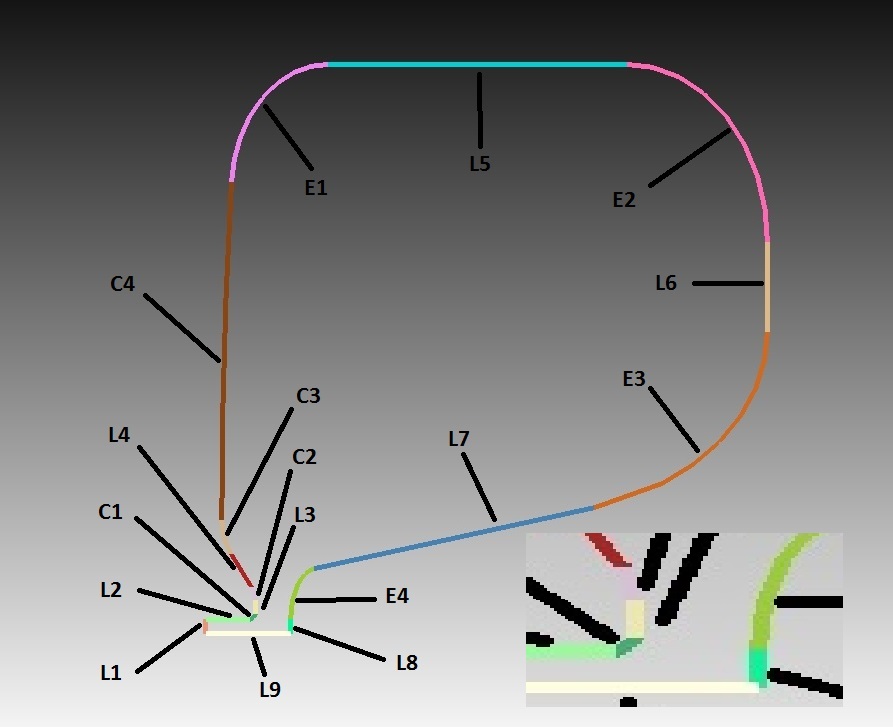
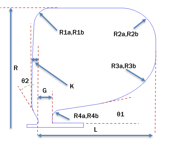
The gun cell geometry is described by seventeen segments, including nine straight lines, four circular arcs and four elliptical arcs, as shown in Figure 1. In the simulation, the beampipe radius L1 and cathode flat area L8 are set at . Beampipe length L2 is set at . The other 14 segments are described by 19 independent geometric parameters, as shown in Figure 2.
The most important optimization goal of the gun cell design is the high launching electric field on the cathode, which determines the beam transverse brightness [28]. Also the total RF power should be as small as possible. Other considerations include the RF frequency, peak power density, peak electric field, the practical cavity size limit, the accommodation of the cathode and laser system and so on. These design goals and limits are defined as objectives and constraints in MOGA, as listed in Table 1.
| Objectives | Constraints |
|---|---|
| With total voltage : | Peak surface field |
| 1) Maximize lauching field | Peak power density |
| 2) Minimize total RF power | RF frequency |
| Cavity radius | |
| Extrusion on anode side |
In MOGA, we chose a population and calculated up to th generation. The Pareto fronts plotted at are shown in Figure 3. Good convergence has been achieved at . The Pareto front clearly shows the trade-off between a high and a low . On the Pareto front of , we chose a geometry with and the minimum as the optimized solution, indicated as the dark dot in Figure 3.
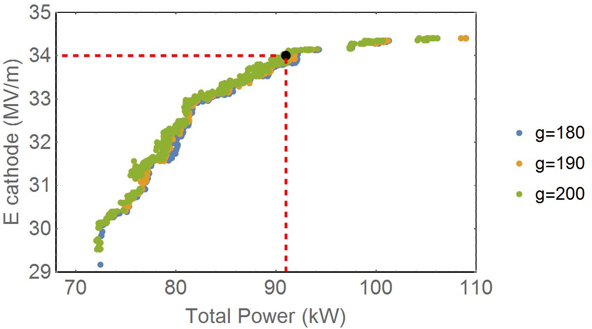
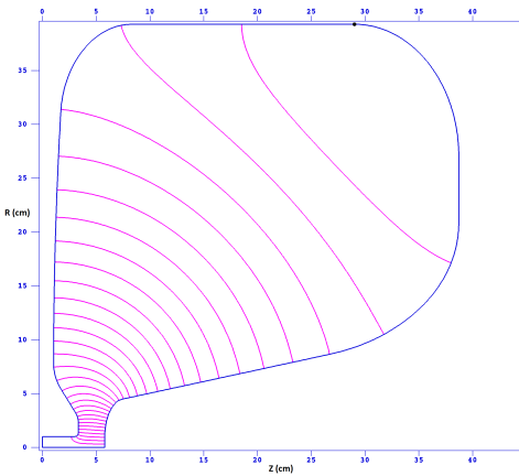
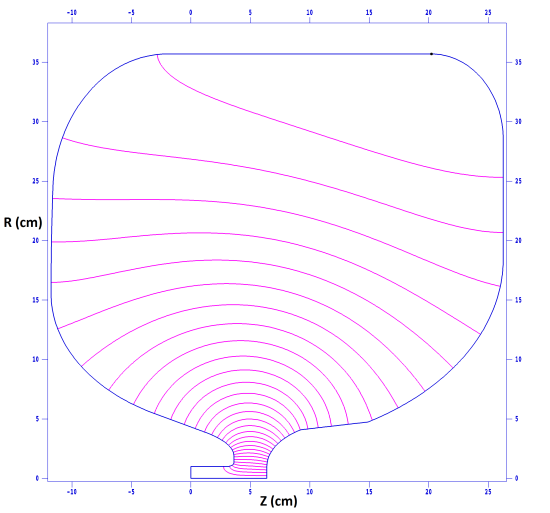
The SUPERFISH E field plot and main RF parameters of this optimized solution are shown in Figure 4 and Table 2. Compared with the APEX gun, of this design has increased significantly from 19.5 to . This improvement is mainly due to the decrease of the accelerating gap width from 4 to . Reducing the beampipe radius from 1.5 to also helps concentrating the E field along the beam axis. is maintained at almost the same level as for APEX with input power. The output energy increases slightly from 750 to . Due to the large enhancement of , both and are inevitably increased significantly compared to APEX. Still the ratio / is lower than APEX.
| Cavity parameters | Gun Cell | 2nd Cell | APEX |
| Radius (cm) | 39.3 | 39.1 | 36.0 |
| Length (cm) | 38.7 | 36.0 | 35.0 |
| Accelerating gap width (cm) | 2.5 | 4.6 | 4.0 |
| Beam pipe radius (cm) | 1.0 | 1.0/1.5 | 1.5 |
| RF frequency (MHz) | 162.5 | 162.5 | 185.7 |
| Total voltage (kV) | 820 | 820 | 750 |
| Total power (kW) | 90.7 | 85.4 | 88.5 |
| Peak power density (W/cm2) | 32.1 | 29.8 | 22.8 |
| Cathode launching field (MV/m) | 34.0 | NA | 19.5 |
| Peak surface field (MV/m) | 37.0 | 24.7 | 24.0 |
| / | 1.09 | NA | 1.23 |
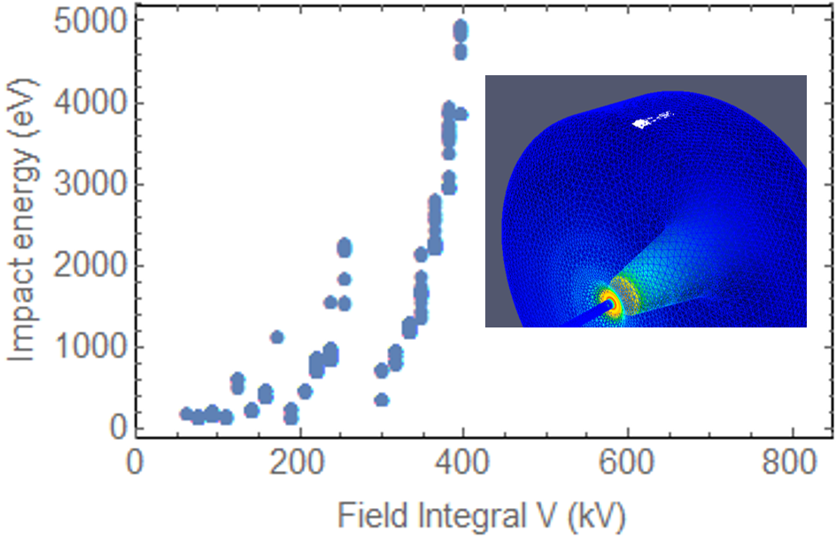
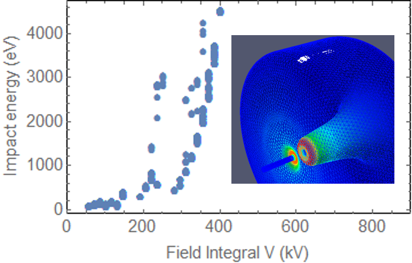
Since the cavity will be operated under Continuous Wave (CW) mode for high repetition operations, the MultiPacting (MP) resonance performance needs to be examined. MP simulations are carried out with Track3P of ACE3P to identify the resonant motions that can produce hazardous MP. The MP impact energy spectrum is shown in Figure 5. No MP pattern is found at the operating power level. Similar to APEX, some MP patterns appear at low power range, mainly located around the outer corner on the anode wall.
3.2 The 2nd Cell Design
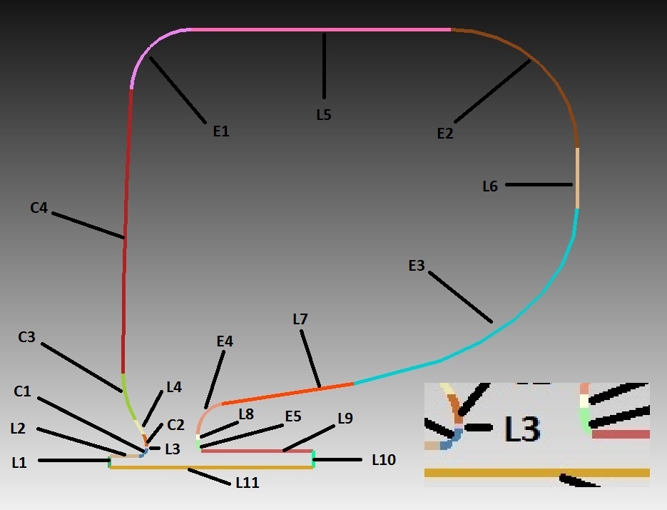
The 2nd cell geometry is similar to the gun cell except there is no cathode plug. It is described by twenty segments, including eleven straight lines, four circular arcs and five elliptical arcs, as shown in Figure 6. Beampipe radii L1 and L10 are set at and respectively. Beampipe length L2 and L9 are set at . The remaining 16 segments are described by 21 independent parameters.
The main function of the 2nd cell is to provide further acceleration for electron beams. For a fixed total voltage, we choose the low peak surface E field and the low RF power loss as the design priorities. Other considerations include the RF frequency, the peak power density, the practical size, the connection to the gun cell and the space for installing the focusing solenoid. The beam dynamics simulation [27] shows that the focusing solenoid should be placed close to the cathode to achieve good emittance compensation, thus the accelerating gap of the 2nd cell cannot be too large. At the same time, the gap can neither be too small considering the restriction on the total RF power. The objectives and constraints in MOGA are listed in Table 3.
| Objectives | Constraints |
|---|---|
| With total voltage : | Accelerating gap plus chamfers on both ends |
| 1) Minimize peak surface field | Peak power density |
| 2) Minimize total RF power | RF frequency |
| Cavity radius | |
| Extrusion one anode side |
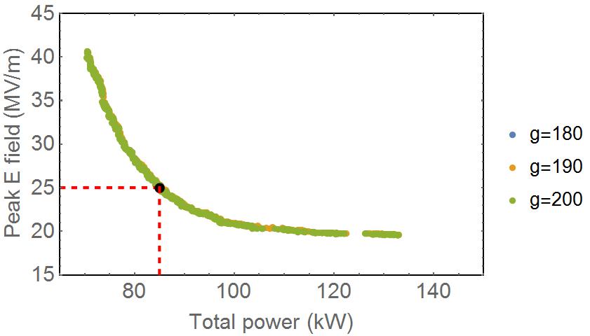
Same as the gun cell, we chose a population and carried out the calculation up to generation. Good convergence has been achieved at , as shown in the Pareto front plot in Figure 7. The Pareto front shows a trade-off between a low and a low as expected. On the Pareto front of , we chose a geometry with and the minimum as the optimized solution, indicated as the dark dot in Figure 7.
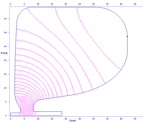
The SUPERFISH E field plot and the main RF parameters of this solution are shown in Figure 8 and Table 2. Compared with the gun cell, the gap width is increased to 4.6 cm to reduce and . The radial size is similar to the gun cell right below . The total RF power at is also similar to the gun cell.
The MP simulation results by ACE3P is shown in Figure 9. Same as the gun cell, no MP is found at the operational power level. Some MP patterns appear at the low power level, mainly located around the outer corner on the anode wall.
3.3 Two-cell Cavity Design
With the design of each cell done, they are put together to make the complete two-cell cavity, as shown in Figure 10. The distance between the cells is set large enough to prevent RF coupling but also small enough to minimize the beam size growth along the structure, which would lead to a consequent emittance increase at the solenoid due spherical aberrations. An injection beamline with this two-cell cavity has achieved a normalized emittance 0.09 m with charge and peak current [27], which is a significant improvement over the state-of-art CW guns.
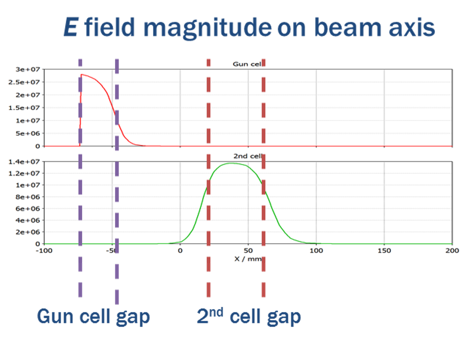
The RF coupling between the two cells is extremely weak. The cutoff frequency of TE11 and TM01 mode of the beampipe are:
| (2) |
both of which are much larger than the cavity operating frequency. The decay length of each mode:
| (3) |
both of which are much smaller than the length of the beampipe between the two cells . The plots of E field on axis when driving each cell are shown in Figure 11.
4 Discussion
4.1 General Geometic Effects of the Re-entrant VHF Gun Cavities
During the design of APEX2 gun cavity with MOGA, we found some general correlations between certain geometric parameters and the RF properties for such re-entrant VHF gun cavities.
-
1.
With fixed , is mainly determined by the gap width .
-
2.
is located at the edge of the cathode flat area. The smaller the cathode flat area, the lower the ratio can be.
-
3.
Cavities with larger radius , smaller cathode cone angle and larger anode extrusion , as shown in Figure 2, generally tend to have less power loss . Larger elliptical corner radius also helps reduce .
4.2 A Preliminary Gun Cavity Design
Besides the frequency of , we have also considered the option of . From the RF design point of view, the main advantages of a cavity are:
-
1.
The Kilpatrick limit [29] is increased from to . Since the gradient of of has never been demonstrated at VHF range with CW operation, at least to the authors’ knowledge, operating at a higher frequency can reduce the risk of potential RF breakdown.
-
2.
The higher frequency results in smaller cavity size. During the design of cavity, we limit the cavity radius comparable to APEX, which compromises the reduction of the total power consumption. For the cavity, the same radius restriction becomes relatively larger due to the shorter wavelength. Thus during the opimization, MOGA can explore the geometric parameter space more extensively for the better solutions.
A preliminary gun cell cavity design is shown in Figure 12, with its main parameters listed in Table 4. The result looks promising. Due to the reduced eigenmode wavelength and fixed cathode flat area, the ratio is decreased. With the same kV, both and are reduced significantly. decreases to , given the same at , which likely can be restored back to by reducing the cathode flat area.
| Cavity parameters | 216.7 MHz | 162.5 MHz |
|---|---|---|
| (cm) | 35.7 | 39.5 |
| (cm) | 38.0 | 38.7 |
| width (cm) | 2.7 | 2.5 |
| (cm) | 1.0 | 1.0 |
| (kV) | 820 | 820 |
| (kW) | 55.8 | 90.7 |
| (W/cm2) | 25.4 | 32.1 |
| (MV/m) | 32.1 | 34.0 |
| (MV/m) | 37.0 | 37.0 |
| / | 1.15 | 1.09 |
4.3 Future Development of MOGA-based RF Cavity Design Method
The design of APEX2 gun cavity has shown the MOGA-based method is a very useful tool for RF cavity design. There are still several improvements to carry out in the future to make this method more efficient and applicable to more design cases:
-
1.
Replace SUPERFISH with a modern Linux-friendly 2D field solver with more efficient calculation and more flexible geometry definition. Explore 3D field solvers.
-
2.
Explore other MOGAs beyond NSGA-II that can be particularly compatible with field solvers.
-
3.
Build the program portable to large scale computer cluster to fully utilize the capability of parallel computing.
5 Conclusion
The RF design of a two-cell re-entrant VHF RF gun cavity has been presented in this paper. The optimization has led to a significant increase of and compared to the previous generation of CW normal-conducting guns (19.5 to and to ). This improvement is likely to lead to a considerable enhancement of the injector beam brightness.
A novel RF cavity design method has been developed and implemented in the design procedure. Combining the GA, the EM field solver and the parallel computing, this method proves to be a useful tool for the RF cavity design.
6 Acknowledgments
The authors would like to thank Dr. Houjun Qian at Deutsches Elektronen-Synchrotron, Germany and Dr. Changchun Sun at LBNL for the helpful discussions. This work is supported by Director of Science of the U.S. Department of Energy under Contract No. DE-AC02-05CH11231. The research used resources of the National Energy Research Scientific Computing Center, a U.S. Department of Energy Office of Science User Facility operated under Contract No. DE-AC02-05CH11231.
References
- [1] J. Galayda, The LCLS-II: a high power upgrade to the LCLS, 9th International Particle Accelerator Conf. Proc. IPAC2018 (2018) MOYGB2.
- [2] W. Decking, H. Weise, Commissioning of the European XFEL accelerator, 8th International Particle Accelerator Conf. Proc. IPAC2017 (2017) MOXAA1.
- [3] D. Filippetto, H. Qian, Design of a high-flux instrument for ultrafast electron dffrection and microscopy, J. Phys.B: At. Mol. Opt. Phy. 49 (2016) 104003.
- [4] A. Bartnik, C. Gulliford, I. Bazarov, I. Cultera, B. Dunhum, Operational experience with nanocoulomb bunch sharges in teh cornell photoinjector, Phys. Rev. ST Accel. Beams 18 (2015) 083401.
- [5] R. Akre, D. Dowell, P. Emma, J. Frisch, S. Gilevich, G. Hays, P. Hering, R. Iverson, C. Limborg-Deprey, H. Loos, A. Miahnahri, J. Schmerge, J. Turner, J. Welch, W. White, J. Wu, Commissioning the linac coherent light source injector, Phys. Rev. ST Accel. Beams 11 (2008) 030703.
- [6] A. Arnold, J. Teichert, Overview on superconducting photoinjectors, Phys. Rev. ST Accel. Beams 14 (2011) 024801.
-
[7]
F. Sannibale, D. Filippetto, H. Qian, C. Mitchell, F. Zhou, T. Vecchione, R. K.
Li, S. Gierman, J. Schmerge,
High-brightness beam tests of the
very high frequency gun at the advanced photo-injector experiment test
facility at the lawrence berkeley national laboratory, Review of Scientific
Instruments 90 (3) (2019) 033304.
arXiv:https://doi.org/10.1063/1.5088521, doi:10.1063/1.5088521.
URL https://doi.org/10.1063/1.5088521 - [8] F. Sannibale, D. Filippetto, M. Johnson, D. Li, T. Luo, C. Mitchell, J. Staples, S. Virostek, R. Wells, J. M. Byrd, Upgrade possibilities for continuous wave rf electron guns based on room-temperature very high frequency technology, Phys. Rev. ST Accel. Beams 20 (2017) 113402.
-
[9]
A. Konak, D. W. Coit, A. E. Smith,
Multi-objective
optimization using genetic algorithms: A tutorial, Reliability Engineering
& System Safety 91 (9) (2006) 992 – 1007, Special Issue -
Genetic Algorithms and Reliability.
doi:https://doi.org/10.1016/j.ress.2005.11.018.
URL http://www.sciencedirect.com/science/article/pii/S0951832005002012 - [10] J. H. Holland, Adaptation in Natural and Artificial Systems, MIT Press, Cambridge, MA, USA, 1992.
-
[11]
I. V. Bazarov, C. K. Sinclair,
Multivariate
optimization of a high brightness dc gun photoinjector, Phys. Rev. ST Accel.
Beams 8 (2005) 034202.
doi:10.1103/PhysRevSTAB.8.034202.
URL https://link.aps.org/doi/10.1103/PhysRevSTAB.8.034202 -
[12]
C. Sun, D. S. Robin, H. Nishimura, C. Steier, W. Wan,
Small-emittance
and low-beta lattice designs and optimizations, Phys. Rev. ST Accel. Beams
15 (2012) 054001.
doi:10.1103/PhysRevSTAB.15.054001.
URL https://link.aps.org/doi/10.1103/PhysRevSTAB.15.054001 -
[13]
Y. Li, W. Cheng, L. H. Yu, R. Rainer,
Genetic
algorithm enhanced by machine learning in dynamic aperture optimization,
Phys. Rev. Accel. Beams 21 (2018) 054601.
doi:10.1103/PhysRevAccelBeams.21.054601.
URL https://link.aps.org/doi/10.1103/PhysRevAccelBeams.21.054601 - [14] L. Wang, P. Emma, Y. Nosochkov, T. Raubenheimer, M. Woodley, F. Zhou, C. Papadopoulos, J. Qiang, M. Venturini, Moga optimization design of lcls-ii linac configurations, 36th International Free Electron Laser Conf. Proc. FEL2014.
-
[15]
R. Bartolini, M. Apollonio, I. P. S. Martin,
Multiobjective
genetic algorithm optimization of the beam dynamics in linac drivers for free
electron lasers, Phys. Rev. ST Accel. Beams 15 (2012) 030701.
doi:10.1103/PhysRevSTAB.15.030701.
URL https://link.aps.org/doi/10.1103/PhysRevSTAB.15.030701 - [16] A. Chincarini, P. Fabbricatore, G. Gemme, R. Musenich, R. Parodi, B. Zhang, Headway in cavity design through genetic algorithms, IEEE Transactions on Magnetics 31 (3) (1995) 1566–1569. doi:10.1109/20.376330.
- [17] S. Shin, J. Chai, Optimization of the rf cavity of the medical purpose electron linac by using genetic algorithm, 29th International Linear Accelerator Conf. Proc. LINAC2014.
- [18] M. Kranjcevic, A. Adelmann, P. Arbenz, A. Citterio, L. Stingelin, Multi-objective shape optimization of radio frequency cavities using an evolutionary algorithmarXiv:arXiv:1810.02990, doi:10.1016/j.nima.2018.12.066.
-
[19]
A. Hofler, B. c. v. Terzić, M. Kramer,
A. Zvezdin, V. Morozov, Y. Roblin, F. Lin, C. Jarvis,
Innovative
applications of genetic algorithms to problems in accelerator physics, Phys.
Rev. ST Accel. Beams 16 (2013) 010101.
doi:10.1103/PhysRevSTAB.16.010101.
URL https://link.aps.org/doi/10.1103/PhysRevSTAB.16.010101 - [20] CST, https://www.cst.com/products/cstmws.
- [21] ANSYS, https://www.ansys.com/Products/Electronics/ANSYS-HFSS.
- [22] COMSOL, https://www.comsol.com/comsol-multiphysics.
- [23] K. Ko, A. Candel, L. Ge, A. Kabel, R. Lee, Z. Li, C. Ng, V. Rawat, G. Schussman, L. Xiao, Advances in parallel electromagnetic codes for accelerator science and development, 25th International Linear Accelerator Conf. Proc. LINAC10.
-
[24]
K. Halbach, R. F. Holsinger, SUPERFISH
- a computer program for evaluation of rf cavities with cylindrical
symmetry, Part. Accel. 7 (LBL-5040) (1976) 213–222. 29 p.
URL http://cds.cern.ch/record/700607 - [25] K. Deb, D. Kalyanmoy, Multi-Objective Optimization Using Evolutionary Algorithms, John Wiley & Sons, Inc., New York, NY, USA, 2001.
- [26] K. Deb, S. Agrawal, A. Pratap, T. Meyarivan, A fast elitist non-dominated sorting genetic algorithm for multi-objective optimization: NSGA-II, in: M. Schoenauer, K. Deb, G. Rudolph, X. Yao, E. Lutton, J. J. Merelo, H.-P. Schwefel (Eds.), Parallel Problem Solving from Nature PPSN VI, Springer Berlin Heidelberg, Berlin, Heidelberg, 2000, pp. 849–858.
- [27] C. Mitchell, , H. Feng, D. Filippetto, M. Johnson, A. Lambert, D. Li, T. Luo, F. Sannibale, J. Staples, S. Virostek, R. Wells, Beam dynatmics studies of an APEX2-based photoinjector, 11th International Particle Accelerator Conf. Proc. IPAC2019 (2019) TUPTS080.
-
[28]
D. Filippetto, P. Musumeci, M. Zolotorev, G. Stupakov,
Maximum current
density and beam brightness achievable by laser-driven electron sources,
Physical Review Special Topics - Accelerators and Beams 17 (2).
doi:10.1103/PhysRevSTAB.17.024201.
URL https://link.aps.org/doi/10.1103/PhysRevSTAB.17.024201 -
[29]
W. D. Kilpatrick, Criterion for vacuum
sparking designed to include both rf and dc, Review of Scientific
Instruments 28 (10) (1957) 824–826.
arXiv:https://doi.org/10.1063/1.1715731, doi:10.1063/1.1715731.
URL https://doi.org/10.1063/1.1715731