Determination of topological properties of thin samples
by the van der Pauw method
Abstract
We solve the problem of determining basic topological properties of flat samples by performing measurements on their outer edge. The global maximum of four probe resistances shows a characteristic behaviour, which is dependent on the genus (i.e., the number of holes) of the domain. An extension of the van der Pauw method on domains having zero, one, or two holes is presented and discussed. A possibility of measuring topological properties of condensed matter is demonstrated. Experimental results for triply connected domains are presented and explained by continuous symmetry breaking caused by the presence of two holes. The results are consistent with the topological theorem of Hurwitz on the number of automorphisms of Riemann surfaces.
PACS Numbers: 84.37.+q, 73.61.-r, 02.30.Em, 02.60.-x
Keywords: four probe measurements, multiply connected domains, genus of Riemann surfaces, sheet resistance, van der Pauw method, Hurwitz’s automorphisms theorem
1 Introduction
The van der Pauw technique [5, 6] is an important and a convenient method of the measurements of two-dimensional homogeneous systems. This is a particular case of four-probe method, reviewed recently on the occassion of its 100 anniversary [7]. The van der Pauw method is especially attractive because of its insensitivity to the sample shape and size, and contact positions. Influence of inhomogeneities on the measurement results were quantitatively characterised in [8]. The precision of practical applications can be increased by correction of finite size of contacts [9, 10] and direct measurement of contacts resistivity [11]. Methods in which extended contacts are used were presented recently [12]. The key assumption of the classical version of van der Pauw method is that the measured domain is simply connected, i.e., there are no holes.
Recently, a generalization was presented for systems with an isolated single hole [13]. It was demonstrated that the sheet resistance and the Riemann modulus can be measured [14]. Some measurements of a sample with two holes were reported as well, but the research was focused on minimizing the influence of the holes [15]. In fact, the main results were presented for contacts placed inside the sample, on the inner boundaries. In the present paper we adopt a different perspective. We are going to detect a presence of holes and, possibly, their number, by performing measurements only on the outer boundary of the sample. We consider a conductive thin plate with four different point contacts that are located at points and . A current enters the sample at the contact and leaves at the contact , whereas the potential is measured between contacts and . We assume that currents are linear functions of the potentials, i.e., the medium is ohmic. The resistance for contacts and is defined as
| (1) |
For a simply connected domain (i.e., a domain without holes), the famous van der Pauw equation is satisfied [5]:
| (2) |
where and indicates the specific resistivity of the sample with a thickness . The ratio , known as the sheet resistance, can be determined from Eq. 2 provided that measurements of both resistances ( and ) for one arbitrarily chosen location of contacts are performed. We point out that in the simply connected case is a function of . Therefore, experimental data for a series of measurements should form a line on a graph representing versus , see Fig. 3 in [13] and Fig. 1a in [14]. In the multiply connected case the analogical experimental data fill out a two-dimensional region. The generalization of the van der Pauw approach for doubly connected domains (i.e., domains with one hole) is presented in [13]. For an annulus with radiuses and , and four contacts located on one edge (outer boundary) at angles and , the resistance can be expressed as:
| (3) |
where is a geometric parameter related to the Riemann modulus , whereas is the function defined by:
| (4) |
In the simply connected case which means that . Hence .
The formula (3) for resistances is invariant under conformal mapping. Therefore, it is valid for any domain with a single hole. One of the consequences of the explicit solution (3) is the following inequality:
| (5) |
In the doubly connected case we have demonstrated that by measuring maximal four-probe resistances it is possible to determine a Riemann modulus [14], whereas by a single measurement of nine four-probe resistances using six contacts it is possible to determine a Riemann modulus and a sheet resistance simultaneously [17]. In this paper we show how to determine the presence of more than one hole by performing measurements on the outer edge of the sample.
2 Equipotential configurations
In order to obtain interesting quantitative characterization of topological properties it is convenient to consider only a special class of configurations satisfying the condition . Note that in the simply connected case this constraint allows a direct computation of the sheet resistance. Indeed, from Eq. (2) it follows immediately that , i.e.,
| (6) |
where .
A configuration of contacts satisfying the condition will be referred to as equipotential because, due to the reciprocity theorem [23], we always have
| (7) |
Therefore, the condition is equivalent to which means that . The last condition can be easily verified experimentally. Note that choosing arbitrary locations of three contacts on the outer boundary one can always find the location of the fourth contact such that the resulting configuration is equipotential. We point out that Eq. (6) obviously implies that in the simply connected case all equipotential configurations yield the same resistance .
In the presence of holes (i.e., when the studied sample is “multiply connected”) we can study dependence of the “equipotential” resistance with respect to location of contacts. In particular, we consider equipotential configurations with maximal resistance. Keeping one contact at a fixed position and changing positions of three other contacts (located on the same edge), we were looking for a global maximum of resistance under condition (or ). In the case of an annulus the value of the global maximum of under condition can be explicitly computed using Eq. (5) of [14]:
| (8) |
The obtained maximum value of depends only on the Riemann modulus and (the dependence on is very strong: given by Eq. (8) tends to infinity for ). However, there is no dependence on the location of the first contact. Geometrically, in the case of annulus, we have a continuum number of such configurations corresponding to squares inscribed into the outer circle. Conformal invariance implies that the same property (independence of the maximum on the location of the first contact) characterizes any doubly connected sample.
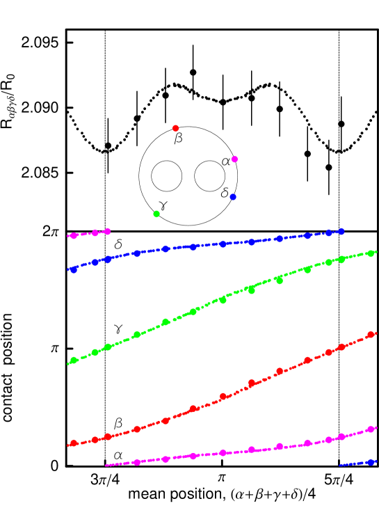
In the case of two holes the global maximum as a function of and under condition depends on the position of , in contrast to the previous cases (disk and annulus). This is observed experimentally (see Fig. 1), where results of measurements are presented conveniently as a function of the mean position of and .
3 Breaking of Möbius symmetries by holes
The essence of the van der Pauw method is the invariance of currents and potentials under conformal deformation of a simply connected domain. The simply connected domain is topologically equivalent to a disk. It is known (see, for instance, [18]) that any conformal self-map of the unit disk to itself is a Möbius transformation:
| (9) |
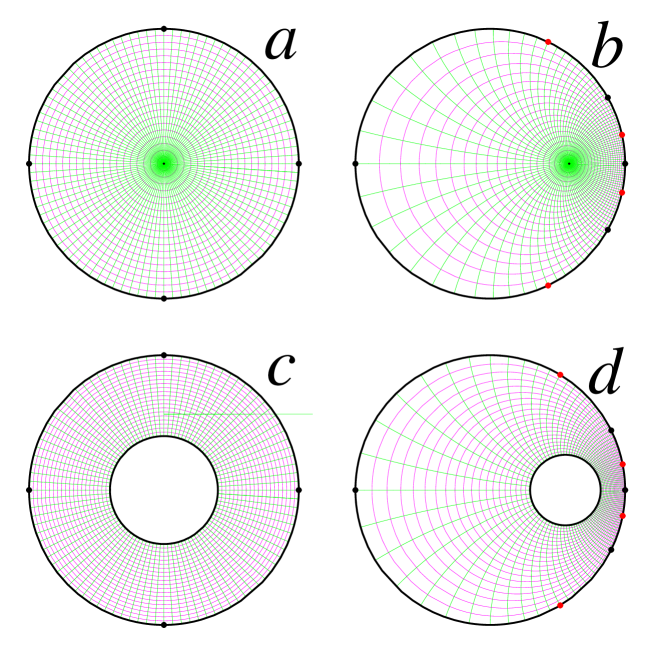
parameterized by one complex () and one real () parameter (the parameter , used in [18], is given by ). Note that , i.e., the center of the disk is mapped into . It is known that a Möbius transformation transforms any circle into a circle (or a straight line), see Fig. 2. The transformation (9) in general is not a symmetry of an annulus mapping it to a disk with an eccentric hole with a center in (see Fig. 2). The Möbius symmetries of an annulus reduce to rotations (obtained for ).
In the case of a disk equipotential configurations are characterized by the cross ratio equal to (compare Eq. 7 in Ref. [19]). The cross ratio is invariant under Möbius transformations. Thus any equipotential configuration can be mapped by a Möbius transform into the square (actually this includes two cases: and , corresponding to two different choices of locations of contacts measuring voltage), compare Fig. 2ab. It means that for the disk all equipotential configurations have the same four probe resistance (1).
In the case of the annulus this full symmetry is broken. Equipotential configurations are symmetric with respect to a diameter. The four probe resistances for equipotential configurations are, as a rule, different. The maximum value correspond to the case of contacts located at vertices of a square, see Fig. 2c. Applying a Möbius transformation we obtain the same resistance but for a different sample, see Fig. 2d. The only exception are configuration of the same shape, transformed into each other by rotations of the annulus. The configuration with a maximal resistance (8), corresponding to the square, is also given up to a rotation.
Möbius transformations (9) preserve the outer disc. We recall that using an appropriate conformal transformation, defined by a holomorphic function of more general form, we can transform a figure of arbitrary shape into the disc. The essence of the van der Pauw approach consists in the fact that four probe resistances are preserved by conformal transformations.
Any domain with two holes can be conformally mapped on a disk with two concentric slits [20] and then, by using another conformal transformation, to an annulus with an additional circular hole. The lack of a rotational symmetry of an annulus with an additional circular hole is apparent. One may expect that the global maximum of as a function of and under condition depends on the position of , in contrast to two previous cases (disk and annulus). This is observed experimentally (see Fig. 1), where results of measurements are presented as function of the mean position of and . Results of our analysis coincide with well-known topological properties of triply connected surfaces with genus . According to the Hurwitz theorem for , the number of automorphisms is finite [21]. A sample with two holes (triply connected, ) cannot have an infinite number of symmetries (including continuous group of rotational symmetries), in contrast to a sample with a single hole (doubly connected, ) or a sample without a hole (simply connected, ). The presence of a second hole breaks the rotational symmetry of the problem.
4 Experiments and numerical simulations for triply connected samples
The measurements were performed similarly as those described in [22]. The sample was made with the same material as reported in [13]; its outer diameter was 290.0(3) mm, and it had two holes of a diameter of 90.0(3) mm with their origins located at distances that were 63.3(3) mm from the sample center (see inset in Fig. 1). One contact was kept at a fixed position and by changing positions of three others, located on the same edge, we were looking for a global maximum of resistance under condition . In fact, due to the reciprocity theorem [23], this is equivalent to a simpler task of searching for configurations such that . A ratio of the specific resistance and the thickness ( in Eq. (2)) was determined in a separate experiment. There is a clear dependence of on the position of a specific contact on the circumference (see Fig. 1). For a shape with a single hole or without a hole, the global maximum of does not depend on the position of . Quite large experimental precision, better than 0.2%, is required for detection of tiny changes in measured resistances. This was achieved using a method described in [22].
Results of measurements were also confirmed by more precise simulations programmed in FreeFem++ environment [24]. Variational formulation [25] was used for numerical solution of two dimensional Laplace equation with the Neumann-type boundary conditions. Gmsh mesh generator [26] was used for Delaunay triangulation [27]. The outer boundary of domain was approximated by polygon having edges while two holes were approximated by polygons with edges, where and . The mesh consisted of 87848 triangles. Point contacts of a sink and a source were approximated by one edge of the polygon. Results of simulations are shown in Fig. 1 by small dots. Full agreement between experiment and numerical simulations was achieved.
According to our earlier papers [13, 14], an analogical experiment, performed for a doubly connected sample, would yield a straight line parallel to the horizontal axis, namely , where the constant is given by
| (10) |
The sample with only one hole (of the same size and location as in the inset of Fig. 1) has and .
In the “pure” van der Pauw case (when and ) we would get the line . Therefore, experiments of this kind can be used as a test for multiconnectedness of the studied sample.
The presented method of measurement allows experimental access to topological properties of materials. One may expect that this could be applied in investigations of self-organized two dimensional structures. Possibility of measuring of topological properties may be particularly important in determination of constituents of metamaterials.
5 Conclusions
We report new results, which are a step further toward generalization of the potential flows on multiconnected domains that are characterized by the four-probe method. We define equpotential configurations of contacts and then we study the behaviour of the maximum value of van der Pauw resistances for these configurations. Performing measurements on the outer boundary, we obtain results qualitatively different in the simply connected case, doubly connected case and triply connected cases.
For the first time, we discuss properties of flows studied by the van der Pauw method on simply, doubly, and triply connected domains while taking into account the symmetry breaking by increased multiconnectivity. We have shown the consequences of a Möbius symmetry of a disk and that the presence of a hole breaks the symmetry. Presence of two holes breaks further the rotational symmetry. Symmetry breaking has an impact on four-probe resistances, evidenced by experiments and numerical simulations.
The global maximum of the four-probe resistance under the condition depends on the number of holes of the domain. For a domain without a hole (simply connected domain, genus ), the maximum of equals . A single hole breaks a Möbius symmetry of the system, and the global maximum of is given by the formula (8) (doubly connected domain, ). The second hole (triply connected domain, genus ) causes a further symmetry breaking of the domain. No continuous symmetries are present, resulting in the dependence of global four-probe resistance on the position of a selected contact on a sample edge. We point out that the presented results for the maxima of resistances are invariant under conformal transformations. Therefore, the results obtained and discussed for a disc with circular holes are valid for any triply connected domain.
We hope that results of this paper will be useful for designing new experimental approaches in material science. A possibility of measuring topological properties of some structures of condensed matter by electrical methods may have potential application in designing and testing new classes of metamaterials [16].
Acknowledgements. The work was supported by funds of Polish Ministry of Science and Higher Education. The authors would like to thank Piotr Sułkowski for his valuable discussions and suggestions.
References
- [1]
- [2]
- [3]
- [4]
- [5] L. J. van der Pauw (1958) Philips Research Reports 13, 1
- [6] L. J. van der Pauw (1958) Philips Technical Review 20, 220
- [7] I. Miccoli, F, Edler, H. Pfnur and C. Tegenkamp (2015) J. Phys.: Condens. Matter 27, 223201
- [8] D. W. Koon, F.Wang, D. H. Petersen and O. Hansen (2014) Journal of Applied Physics 116, 133706
- [9] J. Náhlík, I. Kas̆párková, P. Fitl (2011) Measurement 44, 1968
- [10] J. D. Weiss (2013) Materials Science in Semiconductor Processing 16, 1637
- [11] G. González-Díaz, D. Pastor, E. García-Hemme, D. Montero, R. García-Hernansanz, J. Olea, A. del Prado, E. San Andrés and I. Mártil (2017) Measurement 98, 151
- [12] U. Ausserlechner (2016) Solid-State Electronics 116, 46
- [13] K. Szymański, J.L. Cieśliński and K. Łapiński (2013) Phys. Lett. A 377, 651
- [14] K. Szymański, K. Łapiński and J.L. Cieśliński (2015) Meas. Sci. Technol. 26, 055003
- [15] Z.-H. Sun, J. Zhou, X.-J. Xia and D.-M. Zhou (2017) Phys. Lett. A 381, 2144
- [16] J. Ningyuan, C. Owens, A. Sommer, D. Schuster, and J. Simon (2015) Phys. Rev. X5, 021031
- [17] K. Szymański, K. Łapiński, J.L. Cieśliński, A. Kobus, P. Zaleski, M. Biernacka and K. Perzyńska (2015) Meas. Sci. Technol. 26, 085012
- [18] S. G. Kranz, Handbook of Complex Variable, 1999, Birkhauser Boston
- [19] J. L. Cieśliński (2012) Thin Solid Films 522, 314
- [20] L. V. Ahlfors, Complex Analysis, 1979, 3rd edn, New York: McGraw-Hill
- [21] R.D.M. Accola (1968) Transactions of the American Mathematical Society 131, 398
- [22] K. Szymański and P. Zaleski (2017) IEEE Tran. Instr. Meas. 66, 1243
- [23] B. D. H. Tellegen (1952) Philips Research Reports 7, 259
- [24] F. Hecht (2012) J. Numer. Math. 20251
- [25] K.-J. Bathe, Finite Element Procedures, 1996 New Jersey: Prentice Hall
- [26] C. Geuzaine and J.-F. Remacle (2009) Int. J. Numer. Meth. Eng. 79, 1309
- [27] P. L. George and H. Borouchaki, Delaunay Triangulation and Meshing: Application to Finite Elements, Hermes, 1998