Characterization of an underwater channel for quantum communications in the Ottawa River
Abstract
We examine the propagation of optical beams possessing different polarization states and spatial modes through the Ottawa River in Canada. A Shack-Hartmann wavefront sensor is used to record the distorted beam’s wavefront. The turbulence in the underwater channel is analysed, and associated Zernike coefficients are obtained in real-time. Finally, we explore the feasibility of transmitting polarization states as well as spatial modes through the underwater channel for applications in quantum cryptography.
I Introduction
There are several different methods employed today for communicating underwater. The most widely used method is acoustic, capable of transmitting information over many kilometres stojanovic:03 ; however, the transmission rate is on the order of kilobits per second, limited by the speed of sound in water as well as the modulation rate of acoustic signals heidemann:06 . A second method is to use radio-frequency (RF) signals, which can be easily incorporated into current communication networks. This technique is limited to communication distances on the order of several meters due to high absorption in water at radio frequencies. Both the acoustic and RF implementations suffer from the necessity of bulky and expensive equipment for both transmitting and receiving signals. Over the last decade, using the optical domain for underwater communication has gained increasing interest wiener1980role ; brock2009emerging . With an optimal transmission window between blue and green (400-550 nm) wavelengths, a propagation distance between 50-200 m in clear water can be reached zeng:17 . Higher data rates should additionally be achievable - up to gigabits per second depending on the scheme - allowing for larger data transfers and real-time communication. In fasham:15 , a data rate of Mbps, at a distance of 200 m, has been experimentally achieved.
In a realistic aquatic environment, there are several other factors beyond absorption which can limit the distance and quality of a marine optical communication link, i.e. scattering and turbulence. Scattering in water is dependent on the density and the size of particles in the channel and will contribute significantly to attenuation and therefore to the maximum achievable distance. Scattering is separated into two types: Mie scattering for particles on the order of the wavelength of the light, and Rayleigh scattering for particles much smaller than the wavelength hulst:81 . Especially in water where there are relatively large plankton and mineral particles floating in the water, Mie scattering will have to be considered, along with Rayleigh scattering, due to the water molecules mobley:94 . Another limiting factor when it comes to an actual implementation of an optical link is turbulence nootz:16 ; nootz:17 . A spatially varying index of refraction from temperature and salinity differences through the optical link can result in beam wander as well as higher order distortion effects on the propagating beam. This can contribute both to loss and errors in the transmitted signal. In optical communication, security—affected by factors such as errors in the channel—is an important feature for successful information transfer. Typically, a line-of-sight approach is implemented, making eavesdropping much more difficult, as opposed to the broadcasting method for acoustic and RF communication where the signal is sent in all directions. By considering quantum cryptographic schemes, the security can be further enhanced Uhlmann:15 ; for instance, quantum key distribution (QKD) allows authorized partners to communicate with unconditional security bennett:84 ; gisin:02 ; scarani:09 .
There are several different optical degrees of freedom which can be used to encode information in these QKD protocols. A popular option for direct line-of-sight channels is the polarization of photons, with successful experiments in free-space schmitt:07 ; liao:17 . One limitation with polarization, however, is its inherently limited 2-dimensional Hilbert space, allowing for the maximum transmission of one bit per photon. The orbital angular momentum (OAM) degree of freedom of light, on the other hand, provides the potential of an unbounded state space, and thus unbounded encryption alphabet. Light beams carrying OAM possess a helical wavefront with intertwined helices, i.e. where is an integer number and is the transverse azimuthal angle in polar coordinates allen:92 . These beams possess a doughnut-shaped intensity profile due to the presence of a phase singularity at their centre ( is undefined at the origin in cylindrical polar coordinates). The unbounded state space of these spatial modes allow us to implement high-dimensional quantum communication channels mafu:13 ; mirhosseini:15 ; sit:17 ; bouchard:18b , but they do come with unique challenges. One key challenge that has been observed with free-space communication is that turbulence in the channel can introduce errors in the transmitted information krenn:14 . The measurement of OAM states is heavily dependent on the position of the incoming beam and thus these states are much more prone to errors from turbulence than polarization states which must just maintain their orientation.
Underwater quantum communications have been numerically investigated shi:15 and experimentally demonstrated in laboratory conditions using polarization ji:17 ; zhao:19 , in outdoor conditions using the OAM degree of freedom bouchard:18 , and over a 55 m water channel using polarization hu:18 and spatial modes chen:19 . These experimental investigations have lead to several numerical investigations of QKD in underwater channels tarantino:18 ; guo:18 ; gariano:19 . In this Letter, we investigate the propagation of light through the Ottawa River in Canada’s capital. In particular, we analyze the underwater turbulence by looking at the distorted wavefront and associated Zernike coefficients both obtained from a Shack-Hartmann wavefront sensor. Furthermore, we explore the transmission of polarization states of light and spatial modes of light through the underwater channel for quantum cryptography applications.
II Experiment
The experiments presented here were conducted through the Ottawa River (latitude = 45.541048, longitude = -76.565719) during late August 2018. The water temperature was on average C for the duration of the experiment. However, the ambient temperature varied significantly from the middle of the day to the middle of the night. This contributed to turbulent conditions with water at the surface being heated or cooled more than the water below. Of course since it is a river, there were already naturally varying currents, which moved the water through the beams propagation path resulting in a changing index of refraction.
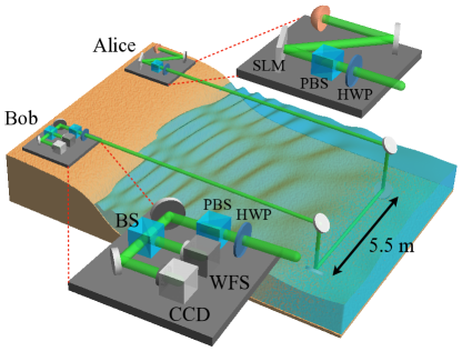
The results discussed in this work were taken using a 532 nm laser diode. The sender and receiver units were mounted on breadboards along the shoreline of the river. As shown in Fig. 1, the sender consisted of the laser, Spatial Light Modulator (SLM), and a half-wave plate. The wave-plates were used to prepare four linear polarization states, i.e. horizontal (H), vertical (V), anti-diagonal (A), and diagonal (D). The SLM is used for preparing the OAM states. This is done by displaying a phase hologram on the SLM and selecting the first diffracted mode from the hologram. The laser beam is then sent from Alice’s breadboard on shore to the first periscope system that brings the beam underwater. The beam then propagates underwater, parallel to the beach, to the second periscope system where it is brought out of the water and sent to the receiver unit, see Fig. 1. In order to eliminate air-water perturbations resulting from surface waves as the beam enters the water, a glass tube, closed at one end, is inserted within the periscope system to create an air-glass-water interface. At the receiver side, we captured the intensity of the beam for the polarization states of H, V, A, and D using a CCD camera. The camera only allows us to gain intensity information about the beam but not the phase. However in order to measure the phase of the beam, we place a Shack-Hartmann wavefront sensor (WFS) at the reciever. This device is made up of a micro-lens array placed in front of a CCD camera. The resulting effect is that the phase at each lens can be determined by the focus point of that lens on the CCD array. This allows one to determine the incidence angle of the given region of the beam and thus the phase relative to the rest of the beam. The accuracy of the wavefront sensor is limited by the number of micro-lenses in the array; the WFS that we use is the Thorlabs WFS20-7AR and has a lenslet array with lenslet pitch of m and focal length of 5.2 mm.
Losses in the link due to scattering played a much larger roll in establishing a quantum channel than was expected. There has been analysis performed looking at the feasibility of quantum communication taking into account many factors including scattering shi:15 . These studies, however, consider at worst the Jerlov Type III ocean water with scattering loss of 1.3 dBm. In our river channel, the total absorption was measured to be 5.4 dBm, significantly higher than even the worst water type considered in the previous calculations. This makes the absorption loss of 0.13 dBm for pure water negligible for practical considerations of achievable distance smith:81 . Due to the large amount of scattering in the river, our experimental tests were limited to 5 m. This high level of scattering was primarily due to large particles in the water (). The Mie scattering model is used when the particles diameter is on the same order as the wavelength of the light. This is typically for particles such as pollen, dust, and water droplets which are approximately the same size as the wavelength of the light. In our channel, since we were near the shore of the river, there was even larger visible plant matter and dirt floating in the water. This resulted in a large amount of light being absorbed or back reflected as opposed to being primarily forward scattered as in the regular Mie scattering regime.
III Results and Discussion
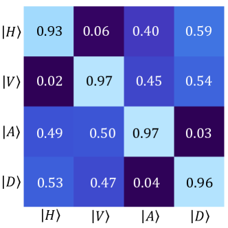
The first goal of this project was to establish that polarization QKD could be achieved in this highly turbulent and highly scattering channel. For the original BB84 protocol bennett:84 , polarization states are chosen from a set of mutually unbiased bases (MUBs). We chose the bases to be and . The defining property of MUBs is that a measurement in the correct basis reveals with certainty the state that the photon was in, while measurement in the wrong basis gives no information about the state of the photon, i.e. . Herein lies the security of QKD: an eavesdropper making a measurement in the wrong basis will be successful only 50% of the time and will introduce errors when they are unsuccessful. The experimental probability-of-detection matrix for the polarization states is shown in Fig. 2. The resultant error rate is 4.01 %, which is below the threshold of 11.0 % necessary to perform QKD with a 2-dimensional BB84 protocol. Though these results are obtained using classical light, single photons will behave in the same way so we can infer that an attempt done with a single photon system would be successful, and will result in a rate of bits per sifted photon.
Although we achieved an error rate below the threshold, there are some residual errors in the system. In free space experiments, the errors are often attributed to optical turbulence, which comes from differences in the index of refraction along the path of propagation as described by the Kolmogorov theory of turbulence kolmogorov:41 . Tip-tilt effects can result in beam wandering, while higher order effects can be present in high turbulence situations, resulting in distortion of the beam’s profile ren:16 ; bouchard:18 . The aberrations in the beam are often visible in the intensity of the beam; however, more precise information lies in the phase of the received beam.
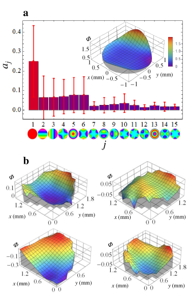
In this experiment we prepared a Gaussian beam at the sender, and measure the wavefront at the receiver. The Gaussian beam should have a spherical phase due to divergence; thus, any variations from this can be attributed to turbulence introduced by the water. From the wavefront measurements, the turbulence can be expanded in terms of the Zernike coefficients, i.e. . Here, and are the radial and azimuthal polar coordinates, respectively; are the Zernike expansion coefficients; are the Zernike polynomials depicted underneath the x-axis of figure 3a; is the Noll index; and and are the radial and azimuthal indices, respectively. The values for the first 15 Zernike coefficients averaged from 30 wavefront measurements are shown in Fig. 3-a along with the reconstructed wavefront from these values. In Fig. 3-b, a sample of four of these individual wavefront measurements is shown. These wavefront measurements show that the beam experienced significant variation upon propagation through the turbulent channel.
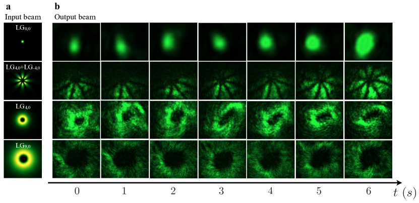
As stated before, the turbulence is also visible in the intensity profile of the beam at the receiver. It is easy to see tip-tilt aberrations from a Gaussian beam as it visibly drifts across the and axis of a camera. The higher order aberrations are often less visible. These aberrations do, however, show themselves very clearly in their effect on higher-order spatial modes. Specifically, the oblique and vertical astigmatism () stretch OAM modes, giving them an elliptical shape, as well as splitting the singularity into lower topological charges. Intensity profiles of OAM and superposition modes are shown in Fig. 4 with consecutive images taken over a time of 6 seconds. The turbulence from the channel is very apparent in the wandering of the LG0,0 mode, and the higher-order aberrations are shown most clearly in the stretching of the LG0,4 mode. In addition to turbulence, all of the modes experience significant intensity fluctuations from changing levels of scattering as well as from objects floating into the beam’s path. The latter is displayed clearly in the images of the petal beam, i.e. . As the correct measurement of spatial modes requires that the position and phase of the beam remain intact, it is clear that, even over a short propagation through water, active wavefront correction or the implementation of adaptive optics would be required to compensate for the aberrations.
IV Conclusion
We have shown that significant challenges present themselves in underwater communication. Despite low absorption from the water at blue-green wavelengths, the scattering from floating particles in the water can severely limit the achievable communication distance. Though scattering will impact the distance, we see that polarization states do maintain their integrity even after propagation through a very highly scattering channel. The second key challenge in an underwater optical channel is turbulence. This has the largest impact on communications using spatial modes. Through the m channel, the OAM modes experience aberrations which will result in errors in a communication protocol. The magnitude of these errors will need to be investigated in future work. Adaptive optics techniques will also need to be investigated to compensate for these errors and allow for communication using spatial modes.
Acknowledgments This work was supported by Canada Research Chairs; Canada Foundation for Innovation (CFI); Canada First Research Excellence Fund (CFREF); Natural Sciences and Engineering Research Council of Canada (NSERC). We thank Denis Guay and the NRC for their help in designing and building the periscopes.
References
- (1) Stojanovic, M. Acoustic (underwater) communications. Wiley Encyclopedia of Telecommunications (2003).
- (2) Heidemann, J., Ye, W., Wills, J., Syed, A. & Li, Y. Research challenges and applications for underwater sensor networking. In Wireless Communications and Networking Conference, 2006. WCNC 2006. IEEE, vol. 1, 228–235 (IEEE, 2006).
- (3) Wiener, T. & Karp, S. The role of blue/green laser systems in strategic submarine communications. IEEE Transactions on Communications 28, 1602–1607 (1980).
- (4) Brock, J. C. & Purkis, S. J. The emerging role of lidar remote sensing in coastal research and resource management. Journal of Coastal Research 1–5 (2009).
- (5) Zeng, Z., Fu, S., Zhang, H., Dong, Y. & Cheng, J. A survey of underwater optical wireless communications. IEEE communications surveys & tutorials 19, 204–238 (2017).
- (6) Fasham, S. & Dunn, S. Developments in subsea wireless communications. In 2015 IEEE Underwater Technology (UT), 1–5 (IEEE, 2015).
- (7) Hulst, H. C. & van de Hulst, H. C. Light scattering by small particles (Courier Corporation, 1981).
- (8) Mobley, C. D. Light and water: radiative transfer in natural waters (Academic press, 1994).
- (9) Nootz, G., Jarosz, E., Dalgleish, F. R. & Hou, W. Quantification of optical turbulence in the ocean and its effects on beam propagation. Applied optics 55, 8813–8820 (2016).
- (10) Nootz, G., Matt, S., Kanaev, A., Judd, K. P. & Hou, W. Experimental and numerical study of underwater beam propagation in a rayleigh–bénard turbulence tank. Applied Optics 56, 6065–6072 (2017).
- (11) Uhlmann, J., Lanzagorta, M. & Venegas-Andraca, S. E. Quantum communications in the maritime environment. In OCEANS 2015 - MTS/IEEE Washington, 1–10 (2015).
- (12) Bennett, C. H. & Brassard, G. Proceedings of the ieee international conference on computers, systems, and signal processing, bangalore, india, 1984 (1984).
- (13) Gisin, N., Ribordy, G., Tittel, W. & Zbinden, H. Quantum cryptography. Reviews of Modern Physics 74, 145 (2002).
- (14) Scarani, V. et al. The security of practical quantum key distribution. Reviews of modern physics 81, 1301 (2009).
- (15) Schmitt-Manderbach, T. et al. Experimental demonstration of free-space decoy-state quantum key distribution over 144 km. Physical Review Letters 98, 010504 (2007).
- (16) Liao, S.-K. et al. Satellite-to-ground quantum key distribution. Nature 549, 43 (2017).
- (17) Allen, L., Beijersbergen, M. W., Spreeuw, R. & Woerdman, J. Orbital angular momentum of light and the transformation of laguerre-gaussian laser modes. Physical Review A 45, 8185 (1992).
- (18) Mafu, M. et al. Higher-dimensional orbital-angular-momentum-based quantum key distribution with mutually unbiased bases. Physical Review A 88, 032305 (2013).
- (19) Mirhosseini, M. et al. High-dimensional quantum cryptography with twisted light. New Journal of Physics 17, 033033 (2015).
- (20) Sit, A. et al. High-dimensional intracity quantum cryptography with structured photons. Optica 4, 1006–1010 (2017).
- (21) Bouchard, F. et al. Experimental investigation of high-dimensional quantum key distribution protocols with twisted photons. Quantum 2, 111 (2018). URL https://doi.org/10.22331/q-2018-12-04-111.
- (22) Krenn, M. et al. Communication with spatially modulated light through turbulent air across vienna. New Journal of Physics 16, 113028 (2014).
- (23) Shi, P., Zhao, S.-C., Gu, Y.-J. & Li, W.-D. Channel analysis for single photon underwater free space quantum key distribution. JOSA A 32, 349–356 (2015).
- (24) Ji, L. et al. Towards quantum communications in free-space seawater. Optics Express 25, 19795–19806 (2017).
- (25) Zhao, S. et al. Experimental investigation of quantum key distribution over water channel. arXiv preprint arXiv:1903.01171 (2019).
- (26) Bouchard, F. et al. Quantum cryptography with twisted photons through an outdoor underwater channel. Optics express 26, 22563–22573 (2018).
- (27) Hu, C.-Q. et al. Transmission of photonic polarization states through 55-meter water: Towards air-to-sea quantum communication. arXiv preprint arXiv:1811.11176 (2018).
- (28) Chen, Y. et al. Underwater transmission of high-dimensional twisted photons over 55 meters. arXiv preprint arXiv:1902.01392 (2019).
- (29) Tarantino, S., Cozzolino, D., Rottwitt, K. & Bacco, D. Feasibility of quantum communications in aquatic scenario. In 2018 IEEE Photonics Conference (IPC), 1–2 (IEEE, 2018).
- (30) Guo, B. et al. Simulations and measurements of polarization states changing in underwater laser transmission. In Ocean Optics and Information Technology, vol. 10850, 108500U (International Society for Optics and Photonics, 2018).
- (31) Gariano, J. & Djordjevic, I. B. Theoretical study of a submarine to submarine quantum key distribution systems. Optics express 27, 3055–3064 (2019).
- (32) Smith, R. C. & Baker, K. S. Optical properties of the clearest natural waters (200–800 nm). Applied optics 20, 177–184 (1981).
- (33) Kolmogorov, A. N. The local structure of turbulence in incompressible viscous fluid for very large reynolds numbers. In Dokl. Akad. Nauk SSSR, vol. 30, 299–303 (1941).
- (34) Ren, Y. et al. Orbital angular momentum-based space division multiplexing for high-capacity underwater optical communications. Scientific Reports 6 (2016).