Elastic Weyl points and surface arc states in 3D structures
Abstract
The study of Weyl points in electronic systems has inspired many recent researches in classical systems such as photonic and acoustic lattices. Here we show how the Weyl physics can also inspire the design of novel elastic structures. We construct a single-phase 3D structure, an analogue of the AA-stacked honeycomb lattice, and predict the existence of Weyl points with opposite topological charges (), elastic Fermi arcs, and the associated gapless topologically protected surface states. We employ full-scale numerical simulations on the elastic 3D structure, and present a clear visualization of topological surface states that are directional and robust. Such designed lattices can pave the way for novel vibration control and energy harvesting on structures that are ubiquitous in many engineering applications.
INTRODUCTION
Phononic crystals and metamaterials have shown new and exciting ways to control the flow of wave propagation in the medium 1 ; 2 ; 3 ; 4 . Recently, the topology of band structures has emerged as a new design tool in this context. The essential idea is to characterize the bulk dispersion topologically and predict its implications on the edges/surfaces of the system. A nonzero topological invariant of the bulk usually implies the existence of edge or surface waves with nontrivial properties, such as directionality and robustness 5 ; 6 ; 7 . Several interesting strategies to manipulate elastic waves have thus been shown 8 ; 9 . However, the studies so far focused mainly on 1D and 2D systems. It is not clear how a 3D elastic structure could be designed to support topological surface states. What special characteristics those surface state would have and how they could be harnessed in engineering settings are some key questions. In this study, we attempt to address these questions by taking inspiration from the Weyl physics.
Weyl semimetals 10 ; 11 ; 12 ; 13 ; 14 have recently attracted significant attention for their exotic features. In Weyl semimetals, the Weyl point refers to the degeneracy point of two bands having linear dispersion in all directions in the 3D reciprocal space. The effective Weyl Hamiltonian is, in general, given by , where is an arbitrary real function, , , and represent group velocity, momentum, and Pauli matrix, respectively. Weyl points behave as the sources or the sinks of the Berry curvature in the reciprocal space. By integrating the Berry flux on a sphere surrounding a Weyl point, we can get the non-vanishing topological charge (or Chern number) associated with it 15 . The Weyl point is robust against small perturbations and cannot be easily gapped unless it is annihilated with another Weyl point with the opposite topological charge 16 . For electronic systems, previous researches have shown many unusual phenomena associated with Weyl points, such as robust surface states 10 and chiral anomaly 17 . Later on, the Weyl physics has shown to be useful in the classical systems of photonic 16 ; 18 ; 19 ; 20 and acoustic lattices 21 ; 22 ; 23 ; 24 ; 25 ; 26 ; 27 .
The implementation of the Weyl physics in elastic structures, however, has been challenging so far. Recently, a self-assembled double gyroid structure that contains Weyl points for both electromagnetic and elastic waves was proposed 28 . Later, a design consisting of a thin plate and beams, which carries both Weyl and double-Weyl points, was also proposed 29 . In spite of these, the experimental demonstrations of elastic Weyl points remain elusive to date. Furthermore, there has not been even a study reporting full-scale numerical simulations in the elastic setting, by which the Weyl physics can be directly visualized and appreciated. This is due to the fact that such structures are extremely intricate to fabricate. At the same time, it is very demanding to computationally simulate their full-scale wave dynamics, because it involves with several types of elastic modes.
In this research, we design a 3D elastic lattice made entirely of beams, which allow both translational and rotational degrees of freedom along their length directions. We employ the finite element analysis (FEA) to obtain a dispersion diagram for the unit cell and discuss its topological features in relation to the Weyl physics. Inspired by widely used 3D hollow structures in engineering, e.g., fuselage, we construct a full-scale hollow structure and show the existence of topological surface states in it. We also elucidate the relation of their directionality with the elastic Fermi arcs in the reciprocal space. We perform a transient simulation of the structure to numerically demonstrate the propagation of nontrivial surface waves. This study therefore paves the way for future research on the design and fabrication of Weyl physics-based structures for engineering applications, such as vibration control and energy harvesting.
DESIGN OF WEYL STRUCTURE
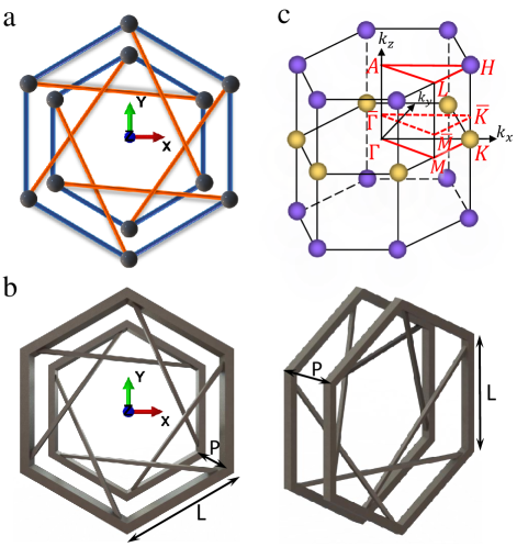
Previous studies in acoustics demonstrated the existence of Weyl points in a AA-stacked honeycomb lattice with chiral interlayer hopping 21 . A schematic of its nearest-neighbor tight-binding model is illustrated in Fig. 1(a). To make an equivalent mechanical system, we would need to use masses and springs that are connected by hinge joints. However, for the more realistic design, we deviate from spring-mass description and propose a unit cell made of space beams as shown in Fig. 1(b). We take beam length mm and height mm. All in-plane beams (parallel to plane) have square cross section of width mm, while out-of-plane beams have square cross section of width mm to reduce the inter-layer stiffness. Note that we can still calculate the effective tight-binding Hamiltonian to analyze topological properties of our elastic structure (Appendix A). In Fig. 1(c), we show the first Brillouin zone with marked Weyl points at the high symmetric points. These are of two opposite charges (Appendix A) and will appear in the simulation results shown in the next section.
To conduct the numerical simulation, we use the commercial FEA software ABAQUS. We model the space beams using the Timoshenko beam elements. We follow the method used in 30 to apply periodic boundary conditions and calculate frequency band diagrams. We use stainless steel 316L as the structural material with elastic modulus GPa, density kg/m3, and Poisson’s ratio , which could be used for current 3D metal printing 31 . We neglect any material dissipation. The out-of-plane beams produce an effective synthetic gauge flux and break the effective time-reversal symmetry at a fixed . Therefore, the system can be treated as an elastic realization of the topological Haldane model 32 .
RESULT
Weyl points in unit-cell dispersion
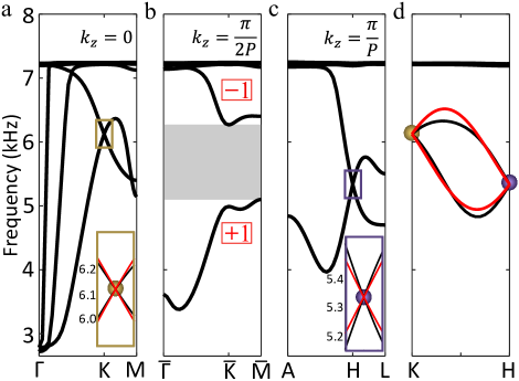
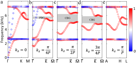
We show the band structure of the unit cell along the irreducible Brillouin zone at in Fig. 2(a). We observe that the th and the th bands, predominately with out-of-plane polarization (see Appendix B), are degenerate at the point around kHz [see the rectangular box and its close-up inset in Fig. 2(a)]. This is a Weyl point in the system, and it is the same as the yellow spheres in Fig. 1(c). We calculate the Weyl charge by fitting the dispersion diagram of a two-band Hamiltonian around the Weyl point (see the red curves in the inset). As a result, we obtain the Weyl charge of from this Weyl point (see Appendix A).
When we plot the dispersion diagram for , the degeneracy of the bands is lifted, and there emerges a band gap between th and th bands, as shown by the grey region in Fig. 2(b). We increase further to plot the dispersion curves at [Fig. 2(c)]. We observe that the band gap closes again, and the two bands establish a degeneracy at 5.34 kHz, but at the point of the Brillouin zone instead of the point. This is the second Weyl point in the system, and it corresponds to the purple markers in Fig. 1(c). As shown in the inset, we again use the two-band Hamiltonian to represent the dispersion characteristics around this Weyl point and find that the Weyl point has topological charge.
In Fig. 1(d), we plot the dispersion diagram along the direction to clearly visualize the Weyl degeneracy at the and points and the existence of a band gap between the th and the th bands when the value lies somewhere in between. We note that the two-band Hamiltonian (red curves) captures this evolution of the bands obtained through the FEA simulations (black curves) reasonably well. We use this effective Hamitonian to numerically calculate the Chern numbers of the two bands above and below the band gap for a fixed . For positive , these are and for the upper and the lower bands, respectively, as marked in Fig. 2(b). This indicates that the band gap is topologically nontrivial.
Directional surface states in supercell
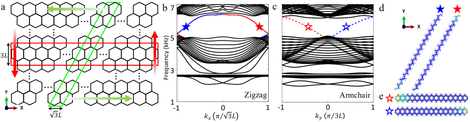
Based on the bulk-edge correspondence of topology, we expect topologically protected boundary modes arising at finite boundaries. To this end, we construct two types of supercells, consisting of 15 unit cells each, having both armchair and zigzag types of finite boundaries. Figure 3(a) shows a schematic of how we choose the two types of the supercells. For the zigzag supercell (see the slanted green box), we apply periodic boundary conditions in both - and -directions. We use free boundary conditions at the top and bottom ends. We fix and plot dispersion diagram in Fig. 3(b). We observe two modes inside the band gap, which are localized on the top (red) and the bottom (blue) ends of the supercell [see Fig. 3(d)]. Based on their slope we can conclude that the top (bottom) end mode would have a negative (positive) group velocity in the -direction [see the green arrows in Fig. 3(a)].
Similarly, we study another supercell with the armchair type of boundaries [see the horizontal red box in Fig. 3(a)]. We show that it supports localized modes on the left and the right ends [see Figs. 3(c) and 3(e)]. These left and right end modes exhibit negative and positive group velocities, respectively [see the red arrows in Fig. 3(a)]. Therefore, it is straightforward to deduce that a wave packet injected at 5.4 kHz (shown as star) on the surface of the full-scale lattice, having simultaneous zigzag and armchair boundaries, would travel counterclockwise for . In the same vein, we expect to obtain a traveling surface wave in the clockwise direction for .
Elastic Fermi arcs in full-scale model
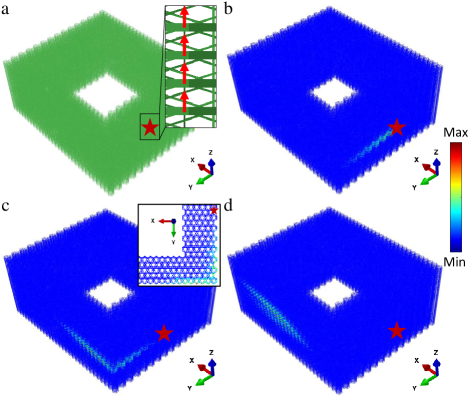
We now demonstrate the existence of surface states in a full-scale 3D structure. We choose a hollow structure for two reasons: (1) such structures are ubiquitous in applications; and (2) they require a reduced amount of computational time for numerical simulations, compared to solid ones. Without fixing , we first excite our system at kHz in the -direction. In Figs. 4(a) and 4(b), we show the -component of steady-state wave displacement when the excitation is placed at the centers of positive (denoted as PXZ, see the red star mark in the inset) and negative (NYZ) planes, respectively. As we can see, the surface states propagate in particular directions and do not spread all across the whole plane. Especially in Fig. 4(b), the wave propagates in the -direction predominantly reflecting the collimation effect 25 .
To investigate further, we perform the fast Fourier transformation (FFT) on the displacement field in the two spatial directions and plot the spectrum in Figs. 4(c) and 4(d). We observe the arc-like pattern of the peak spectral density (in yellow). These are called “Fermi arcs”, also seen as the counterpart representation of the surface states in the reciprocal space. Since the normal vector to the Fermi arcs would determine the direction of the wave’s group velocity, we can deduce from Fig. 4(d) that the wave will propagate in the -direction predominantly given the straight posture of the arc. This thus confirms the aforementioned collimation effect [Fig. 4(b)] in the wavevector space.
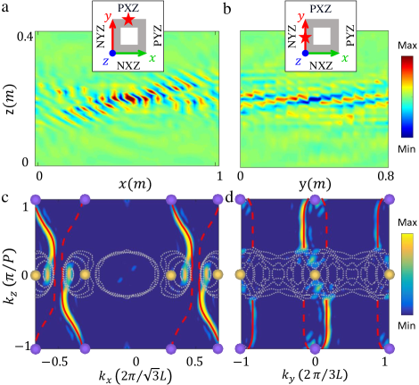
These Fermi arcs could also be obtained from the equi-frequency contour (FEC) analysis on the supercell (see details in Appendix C). To achieve this, we calculate dispersion characteristics of the supercells, as shown in Figs. 3(b) and 3(c), for all values of inside the first Brillouin zone. We then extract the wave numbers for kHz to obtain the red curves in Figs. 4(c) and 4(d). Here, solid curves correspond to the the solutions on the plane of excitation, while the dashed curves represent those on the opposite surface. Evidently, the red solid curves closely match the spectral density arcs obtained from the full-scale simulation. The Fermi arc generally connects the Weyl points of the opposite charges (23, ), but here we see that they connect the two Weyl points (in purple and yellow) roughly but not exactly. This is because the system supports the two Weyl points at different frequencies [see the frequency offset of the yellow and purple points in Fig. 2(d)].
Robust one-way propagation
We now proceed to the full-scale, transient numerical study performed at 5.4 kHz, but for a fixed . Figure 5(a) shows the entire structure. We fix all the degrees of freedom of the nodes on the top and bottom layers. To ensure the excitation with the desired , we apply four-point excitation in the -direction on the th to the th layers on the YZ plane (marked with the red arrows in Fig. 5(a) inset). We use a Gaussian-modulated sinusoidal pulse with the center frequency of kHz, and we fix by increasing the phase of the input signal by from the th to the th layer. From the discussions above, we expect that the wave packet would propagate clockwise when looking from the top (-axis). In Figs. 5(b)–5(d), we plot the displacement amplitude of the system at time ms, ms, and ms, respectively. We observe that the elastic wave remains on the surface of the structure and only travels upward in the clockwise direction (viewing from the top) without obvious reflection at the corners (see Fig. 5(c) and its inset, also Supplementary Movie 1). This, therefore, demonstrates a robust one-way propagation of surface elastic wave in our Weyl structure.
CONCLUSION
We design a 3D mechanical structure – analogous to the AA-stacked honeycomb lattice – by using slender beams. We show that this relatively simple design carries Weyl points at the vertices of the Brillouin zone. We use a two-band Hamiltonian model to describe the dynamics around the Weyl points and calculate their topological charges. We show the finite boundaries of this structure, both zigzag and armchair types, host localized states at a fixed . Using numerical simulations on a full-scale 3D structure, we show the existence of the Fermi arcs and compare them with the results obtained from equi-frequency contour analysis. We highlight two unique wave phenomena in our structure: (i) collimation of the propagating elastic waves and (ii) robust one-way transport of elastic energy around the corners. Our design could be easily scaled up or down, and can be relevant to applications, such as sensing, energy harvesting, and vibration control on 3D elastic structures. Studies on the experimental verification of the elastic surface states are expected in the authors’ future publications.
ACKNOWLEDGMENTS
We thank Dr. Hyunryung Kim, Dr. Ying Wu, and Shuaifeng Li for fruitful discussions. X. S., R. C., and J. Y. are grateful for the financial support from the U.S. National Science Foundation (CAREER1553202 and EFRI-1741685).
APPENDIX A: TIGHT-BINDING MODEL OF AA-STACKED GRAPHENE
We consider the tight-binding model of a AA-stacked graphene with chiral interlayer coupling, as depicted in Fig. 1(a). The unit cell has an in-plane lattice constant and out-of-plane lattice constant in the -direction [see Fig. 1(b)]. Let the intralayer (interlayer) coupling be (). Therefore, we write the Bloch Hamiltonian given by 16 ; 21 ; 27
where denotes the on-site potential, , and . By applying the method16 , we can expand the Hamiltonian near the point [] and obtain the effective Hamiltonian
where is a small -vector deviating from the point, is the unit matrix, and , , are the Pauli matrices.
We use kHz, kHz, and kHz for fitting the two-band dispersion with the curves obtained from the FEA results seen in Fig. 2. The effective Hamiltonian describes a Weyl point at the point, whose topological charge is given by , where Dirac velocities , , and . Therefore, in this case. Similarly, by expanding the Hamiltonian at the point [], we verify that there is another Weyl point with the topological charge of located at the point.
APPENDIX B: UNIT-CELL DISPERSION AND MODE POLARIZATION
In this appendix, we show the modes that are degenerate at the Weyl points are an out-of-plane type with a predominant component. To this end, we define a polarization factor to distinguish bands with different polarization components, where , , and are the -, -, and - components of the eigenvectors. Therefore, the out-of-plane modes, with predominately component, would have the polarization factor close to a unity, while the polarization factors of the in-plane modes would approach zero. We plot the bulk bands of the unit cell – colored with the information about the polarization factors – on the 2D reciprocal plane at various values in Fig. 6. We can clearly see that the Weyl points are formed by the degeneracy of the two bands containing out-of-plane modes (in red).
APPENDIX C: EQUI-FREQUENCY CONTOUR ANALYSIS
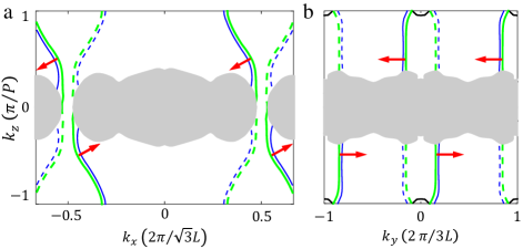
Equi-frequency contour on the the plane, as shown in Fig. 4(c), can be obtained by calculating the band structure of the supercell with the zigzag type boundary. At kHz, we vary from to and from to , to obtain wavevector plots in green as shown in Fig. 7(a). Note that we plot another equi-frequency plot at slightly higher frequency ( kHz) in blue to get a sense of the normal vector, i.e., the group velocity shown by red arrows at . Similarly, result of the plane, from the supercell with the armchair type boundary, is shown in Fig. 7(b). This equi-frequency contour confirms the collimation effect in the direction.
References
- (1)
- (2) Z. Liu, X. Zhang, Y. Mao, Y. Y. Zhu, Z. Yang, C. T. Chan, and P. Sheng, Locally Resonant Sonic Materials, Science 289, 1734 (2000).
- (3) M. I. Hussein, M. J. Leamy, and M. Ruzzene, Dynamics of Phononic Materials and Structures: Historical Origins, Recent Progress, and Future Outlook, Appl. Mech. Rev. 66, 040802 (2014).
- (4) M. Kadic, T. Bückmann, R. Schittny, and M. Wegener, Metamaterials beyond electromagnetism, Rep. Prog. Phys. 76, 126501 (2013).
- (5) K. Bertoldi, V. Vitelli, J. Christensen, and M. van Hecke, Flexible mechanical metamaterials, Nature Reviews Materials 2, 17066 (2017).
- (6) M. Z. Hasan and C. L. Kane, Colloquium: Topological insulators, Rev. Mod. Phys. 82, 3045 (2010).
- (7) X.-L. Qi and S.-C. Zhang, Topological insulators and superconductors, Rev. Mod. Phys. 83, 1057 (2011).
- (8) E. Prodan and H. Schulz-Baldes, Bulk and Boundary Invariants for Complex Topological Insulators (Springer International Publishing, Cham, 2016) arXiv:1510.08744.
- (9) S. D. Huber, Topological mechanics, Nature Physics 12, 621 (2016).
- (10) G. Ma, M. Xiao, and C. T. Chan, Topological phases in acoustic and mechanical systems, Nature Reviews Physics 1 (2019).
- (11) X. Wan, A. M. Turner, A. Vishwanath, and S. Y. Savrasov, Topological semimetal and Fermi-arc surface states in the electronic structure of pyrochlore iridates, Phys. Rev. B 83, 205101 (2011).
- (12) C. Fang, M. J. Gilbert, X. Dai, and B. A. Bernevig, Multi-Weyl Topological Semimetals Stabilized by Point Group Symmetry, Phys. Rev. Lett. 108, 266802 (2012).
- (13) S.-Y. Xu, I. Belopolski, N. Alidoust, M. Neupane, G. Bian, C. Zhang, R. Sankar, G. Chang, Z. Yuan, C.-C. Lee, S.-M. Huang, H. Zheng, J. Ma, D. S. Sanchez, B. Wang, A. Bansil, F. Chou, P. P. Shibayev, H. Lin, S. Jia, and M. Z. Hasan, Discovery of a Weyl fermion semimetal and topological Fermi arcs, Science 349, 613 (2015).
- (14) A. A. Soluyanov, D. Gresch, Z. Wang, Q. Wu, M. Troyer, X. Dai, and B. A. Bernevig, Type-II Weyl semimetals, Nature 527, 495 (2015).
- (15) N. P. Armitage, E. J. Mele, and A. Vishwanath, Weyl and Dirac semimetals in three-dimensional solids, Rev. Mod. Phys. 90, 015001 (2018).
- (16) Z. Fang, N. Nagaosa, K. S. Takahashi, A. Asamitsu, R. Mathieu, T. Ogasawara, H. Yamada, M. Kawasaki, Y. Tokura, and K. Terakura, The Anomalous Hall Effect and Magnetic Monopoles in Momentum Space, Science 302, 92 (2003).
- (17) W.-J. Chen, M. Xiao, and C. T. Chan, Photonic crystals possessing multiple Weyl points and the experimental observation of robust surface states, Nature Communications 7, 13038 (2016).
- (18) H. B. Nielsen and M. Ninomiya, The Adler-Bell-Jackiw anomaly and Weyl fermions in a crystal, Physics Letters B 130, 389 (1983).
- (19) L. Lu, L. Fu, J. D. Joannopoulos, and M. Soljačić, Weyl points and line nodes in gyroid photonic crystals, Nature Photonics 7, 294 (2013).
- (20) L. Lu, Z. Wang, D. Ye, L. Ran, L. Fu, J. D. Joannopoulos, and M. Soljačić, Experimental observation of Weyl points, Science 349, 622 (2015).
- (21) M.-L. Chang, M. Xiao, W.-J. Chen, and C. T. Chan, Multiple Weyl points and the sign change of their topological charges in woodpile photonic crystals, Phys. Rev. B 95, 125136 (2017).
- (22) M. Xiao, W.-J. Chen, W.-Y. He, and C. T. Chan, Synthetic gauge flux and Weyl points in acoustic systems, Nature Physics 11, 920 (2015).
- (23) Z. Yang and B. Zhang, Acoustic Type-II Weyl Nodes from Stacking Dimerized Chains, Phys. Rev. Lett. 117, 224301 (2016).
- (24) F. Li, X. Huang, J. Lu, J. Ma, and Z. Liu, Weyl points and Fermi arcs in a chiral phononic crystal, Nature Physics 14, 30 (2018).
- (25) T. Liu, S. Zheng, H. Dai, D. Yu, and B. Xia, Acoustic semimetal with Weyl points and surface states, arXiv:1803.04284 [Cond-Mat] (2018).
- (26) H. Ge, X. Ni, Y. Tian, S. K. Gupta, M.-H. Lu, X. Lin, W.-D. Huang, C. T. Chan, and Y.-F. Chen, Experimental Observation of Acoustic Weyl Points and Topological Surface States. Phys. Rev. Applied 10, 014017 (2018).
- (27) H. He, C. Qiu, L. Ye, X. Cai, X. Fan, M. Ke, F. Zhang, and Z. Liu, Topological negative refraction of surface acoustic waves in a Weyl phononic crystal, Nature 560, 61 (2018).
- (28) X. Zhang, M. Xiao, Y. Cheng, M.-H. Lu, and J. Christensen, Communications Physics 1, 97 (2018).
- (29) M. Fruchart, S.-Y. Jeon, K. Hur, V. Cheianov, U. Wiesner, and V. Vitelli, Soft self-assembly of Weyl materials for light and sound, PNAS 115, E3655 (2018).
- (30) Y.-T. Wang and Y.-W. Tsai, Multiple Weyl and double-Weyl points in an elastic chiral lattice, New J. Phys. 20, 083031 (2018).
- (31) P. Wang, F. Casadei, S. H. Kang, and K. Bertoldi, Locally resonant band gaps in periodic beam lattices by tuning connectivity, Phys. Rev. B 91, 020103 (2015).
- (32) C. S. Lefky, B. Zucker, D. Wright, A. R. Nassar, T. W. Simpson, and O. J. Hildreth, Dissolvable Supports in Powder Bed Fusion-Printed Stainless Steel,3D Printing and Additive Manufacturing 4, 3 (2017).
- (33) F. D. M. Haldane, Model for a quantum Hall effect without Landau levels: Condensed-matter realization of the ”Parity Anomaly”, Phys. Rev. Lett. 61, 2015 (1988).