Over the Sea UAV Based Communication
Abstract
Unmanned Aerial Vehicle (UAV) aided wireless networks have been recently envisioned as a solution to provide a reliable, low latency cellular link for search and rescue operations over the sea. We propose three different network architectures, based on the technology deployed on the UAV: a flying relay, a flying Base Station (BS) and a flying Remote Radio Head (RRH). We describe the challenges and highlight the benefits of the proposed architectures from the perspective of search and rescue operations over the sea. We compare the performance in term of data rate and latency, analyzing different solutions to provide a Backhaul (BH)/ Fronthaul (FH) link for long coverage over the sea. Results show that a system architecture is not outperforming over the others. A cost function is thus indicated as a tool to find a suboptimal solution.
Index Terms:
5G, UAV, air-to-sea, Base Station, C-RAN, RRH, Relay, MIMO, FSO, mmWave, backhaul, fronthaulI Introduction
Effective and efficient offshore search and rescue operations can save many lives. The significant increase in the number of small boats attempting to cross Mediterranean sea and lives lost on these attempts highlighted importance of these operations [1]. Information sharing and communication among rescue vessels and rescuees, will significantly improve the efficiency and effectiveness of search and rescue operation over the sea. A reliable and robust communication system is, therefore, a crucial asset for search and rescue operations over the sea.
Existing satellite services are expensive and suffer from high latency. Moreover, small (unregistered) vessels normally do not have satellite mobile phones onboard. Common European standards, specifically designed for use in emergency, e.g. Trans-European Trunked Radio (TETRA), have a very slow data transfer. In this paper, we are motivated by the need of investigating new technologies to realize an effective communication system in an event of emergency over the sea for enhancing timely rescue and recovery operations. In a recent work [2], we presented two different UAV-assisted wireless network architectures as promising solutions to extend the coverage of the terrestrial network and assist the rescue and recovery operations. UAVs introduce a high level of mobility and flexibility to the network and can be deployed where and when they are needed. UAVs can complement existing cellular networks when additional capacity or coverage is needed, e.g. in outdoor music concerts or sport events [3]. In addition, given the high dynamism, UAVs are envisioned as the immediate responder to resurrect the communication link in post disaster scenarios (e.g. project ABSOLUTE). Beyond the benefits to the network, using UAVs to provide connectivity for search and rescue operations over the sea is important to prevent serious losses, for example, by saving lives. In fact, high quality communication between rescuers and people in distress enable applications like videos streaming, users location and monitoring/recognition. Even more attractive from a search and rescue point of view, one or more UAVs attached to the network as flying User Equipments could act as mechanical eyes to monitor wide sea areas. For this reason, we believe not enough attention has been given to UAV as communication provider for search and rescue operations over the sea.
We classify UAV-assisted networks based on the role of UAV into three main groups: 1) UAV carries a BS, 2) UAV is loaded only with the radio front end or RRH and, 3) UAV acts as a mobile relay.
Deployed as flying BSs in the sky, UAVs are able to adjust their locations dynamically and provide on demand services to the ground users according to their real-time locations. This first approach has been widely investigated, especially for emergency and post disaster scenarios. For instance, the work in [4] suggests low cost UAVs for search and rescue operations in the mountain to survey and locate individuals in distress. Moreover, the flying BSs architecture has been proposed for search and rescue operations in deep open pit mines [5] or disaster struck scenarios [6].
Using a UAV to relay the cellular networks can reduce the weight on UAV’s payload while extending the ground cellular coverage to remote and dedicated areas where infrastructure is not available or expensive to deploy [7].
UAVs can be integrated into mobile networks acting as flying RRH in similar way as in a Cloud Radio Access Networks (C-RAN) network, where in the original terrestrial configuration several fixed RRHs serve as access points to the network and are connected to a Base Band Unit (BBU) that performs the major part of the processing [8]. Flying RRHs could be deployed to increase channel quality, user throughput and the energy efficiency of the system [9], but it introduces challenges that range from the high capacity required on the FH, to strict latency and jitter requirements.
The rising number of works considering the aforementioned deployment approaches motivates us to investigate the benefits and challenges of these technologies while deployed on UAVs. In this paper, we take a new look at the challenges and appealing features of the approaches presented above, from the perspective of search and rescue operations over the sea. Specifically, the contributions of this paper are: an understanding of challenges and benefits of the three UAV assisted network architectures in a realistic search and rescue scenario over the sea; a performance comparison based on different indicators; a cost function to design the suboptimal approach considering different BH technologies.
II System architectures description and related challenges
In most cases, search and rescue operations for migrants at sea usually take place off-shore [1]. In this area, typically, the cellular coverage is very low or absent. This lack motivates to deploy a wireless UAV-aided wireless network to provide temporary cellular connectivity for all the entire length of the search and rescue operations. The network is composed by a UAV that can act as flying relay, flying BS or flying RRH to serve the users. Based on the technology deployed on the UAV, three different end-to-end network architectures can be considered:
-
I
Core Network - Ground Base Station - Relay - Users
-
II
Core Network - Ground Base Station - Flying Base Station - Users
-
III
Core Network - Base Band Unit - Flying Remote Radio Head - Users
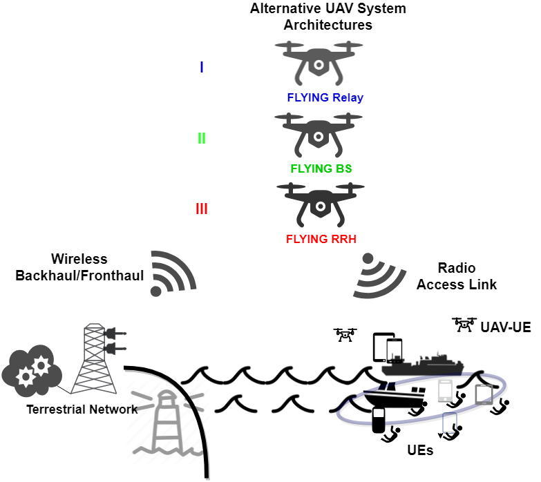
In the first system architecture, we consider the UAV to work as a relay type 0, where under amplify and forward scheme, half of time slots are assigned to transmit the signal to the UAV and the second half to listen the signal from the ground BS. The solutions proposed with the architectures II and III require, respectively, a wireless BH link and wireless FH link to the core network. Given limited resources in terms of access and BH/FH link, the objective of this paper is to compare these three different approaches in term of data rate, latency and energy efficiency.
II-A Comparison of the proposed architectures
The deployment of the proposed architectures over the sea faces challenges of complexity, energy consumption and sustainable BH load. On one hand, the UAV has a limited volume, weight and available energy. On the other hand, such a critical scenario has challenging demands, such as high reliability and low energy consumption. Thus, the identification of the candidate system architecture is not trivial since it should consider the following key factors. Firstly, the off-shore scenario taken into consideration is critical from a communication point of view, since requires a long range BH/FH link to connect the UAV to the core network. Secondly, to be efficient and use new immersive technologies, search and rescue operations demand for reliable, low latency and medium-high data rate services, i.e. access side of the network. Thirdly, the existing communication technology, such as satellite, are not be able to support primary performance targets like throughput and packet delay.
Now we will have a closer look at the candidate architectures:
II-A1 Relay UAV
Compared to a UAV-BS, relays require less processing power, because their radio equipment are relatively simple. Hence, they can work with a light payload UAV, reducing costs and power consumption. However, this solution is expected to offer less than twice the throughput a flying BS can offer, due to the sharing of resources between communication with the UEs and relaying to the BS [9].
II-A2 UAV-BSs
Flying UAV-BSs can potentially provide enough data rate to satisfy the estimated data capacity required in emergency scenarios over the sea. This comes at the expense of high deployment hardware cost and weight, and a consequent reduction in the endurance of the UAV, that might affect the search and rescue mission time. Moreover, providing a long range BH represents a main challenge of this configuration.
II-A3 RRH-UAV
The RRH-UAV approach has the advantages of a C-RAN network. In its conventional configuration, the radio element of the base station (RRH or Remote Access Unit (RAU)) is separated from the element processing the baseband signal (BBU), which is centralized in a single location or virtualized in the cloud. Thus, an onboard BBU is not required, alleviating the weight and the payload complexity on the UAV. Moreover, the C-RAN configuration enhances resource management and reduce power consumption on the UAV by centralising the baseband processing. Howewer, such a functional split requires to connect the BBU and the flying RRH through a long range wireless, high speed, low latency link. Conventional FH interfaces have large overhead and may fall short in support of this architecture. Moreover, the required capacity on the FH increase linearly if an antenna array is deployed on the UAV to perform beamforming techniques. FH constraints in conventional C-RAN networks are the focus of several research works [10], but the effects of these limits on UAV communication has not been properly investigated. In fact, caching techniques have been proposed to offload the limited UAV-BBU FH [11], while other works consider unpractical fiber optical cable links or general high speed and distortion free FH links [12]. In this paper, using a conventional FH dimensioning, we highlight the impact of FH capacity and latency requirements for search and rescue operations missions.
II-B Wireless BH/FH analysis for long range coverage at sea
In terrestrial networks, when the optical fiber connectivity is unavailable, the main solution is a long range wireless BH/FH. Due to cost, latency and implementation issues, popular options like microwave point to point and satellite links cannot be considered attractive for the UAV BH/FH link over the sea. Consequently, we have identified different wireless technologies (Table I) to come up with a cost effective technological option for the BH/FH link between the UAV and the core network.
The first solution is represented by reaching the UAV by a BS on the shore operating at sub 6GHz, giving availability of a licensed but limited spectrum. Wider component carrier bandwidth up to 400 MHz and low spectrum cost could be reached shifting the operating frequency to higher bands, such as millimeter Wave (mmWave) band. The propagation properties of the radio signal at these frequencies, together with the specific atmospheric conditions over the sea, open the way to several research challenges and opportunities: the high level of humidity leads to an additional free space absorption [13] but, at the same time, atmospheric ducts, result of different refractive indices of the layers over the water, can be exploited to propagate the signal over longer distance [14]. Although mentioned, the mmWave option is not focus of this paper, and it is left for future investigation. In combination with the operating frequency, to increase the range of the over the sea BH solutions, we have considered to employ multiple antennae on the transmitter. In fact, the use of multiple antennae in transmission in Line of Sight (LOS), although it might not achieve Multiple Input Multiple Output (MIMO)’s capacity-multiplying effect, still enhances the coverage range. As last, we mention also the Free Space Optics (FSO). Even if promising for its high data rate and low spectrum cost, this technology is very sensitive to inclement weather conditions.
| Technology | Benefits | Challenges | Data Rate | Bandwidth |
|---|---|---|---|---|
| sub6GHz SISO | Long range, Robust to over-the-sea atmospheric conditions | Limited Spectrum | 20 MHz | |
| sub6GHz - 2x2 MIMO | Increase in coverage range | LOS Conditions are particularly stressy | 20 MHz | |
| sub6GHz - massive MIMO | Array gain for range extension | Correlation between antenna elements when transmitting at long range | 20 MHz | |
| Free space Optics | Potential high data rate | Greatly affected by weather conditions. Sensitive to Pointing and Vibration loss, Higher cost | / | |
| mmWave | High availability of spectrum, ducting effect increase the coverage range | Sensitive to multiple over-the-sea atmospheric conditions, existing path loss model over the sea are valid only for short range | 400 MHz |
III System model and problem formulation
Let us consider a set of users in an area A over the sea that cannot be served by any terrestrial BS. The users are split and randomly concentrated in two different areas of same diameter r, representing the people in distress and the rescue team. A UAV is hovering at altitude to transmit signals to the users on the sea. We assume that the main factor which affects the service quality offered by the UAV is pathloss, as the UAV operates at LOS with no Downlink (DL) interference from other cells. In order to derive the data rate and the latency for the three different system architectures, it is imperative to find an air to sea path loss model.
III-A Air to Sea Channel Model
Modeling wireless channels for over the sea wave propagation is a relatively new research topic. The UAV-to-ground path loss is generally computed using the urban model in [15], that adds to the free space loss an additional one which depends on whether there is LOS between the UAV and the users or not. Since the unique characteristics of over the water environment, from the roughness of the sea surface to the specific atmospheric phenomena occurring over the sea (humidity, evaporation ducting), this model might be inadequate. A robust wireless channel model for over the sea wave propagation has not been developed yet and the existing approaches vary with frequencies, technology used and implementation scenario.
In this paper, as in the most of channel models in literature, we consider the sea surface to be smooth and we do not consider any ducting effect. Consequently, we adopt a two ray model to take into consideration the reflection component of the sea. The path loss can be expressed as follows:
| (1) |
where d is the distance between the UAV and the user.
III-B Transmission Model
To compare the DL channel capacity at user served by the UAV network for each of the proposed network architectures, we have computed the channel capacity on both ground BS/BBU-UAV, and UAV-users transmission links.
III-B1 UAV-User Links
given the channel model presented in III-A, the average path loss depends on the location and the height of the user i and the UAV. Based on the path loss, for a generic user i, it is possible to compute the power received, . Recalling that the average Signal-to-Noise Ratio (SNR) at user i can be expressed as , where N is the noise power, the corresponding DL access data rate for each network architecture is shown in Table II.
III-B2 Ground BS/BBU-UAV Links
For the BH and FH link to the UAV, we consider a fixed distance much larger than the distance UAV-users, to represent the offshore situation of the UAV. The corresponding DL backhauling/fronthauling rate at the UAV depends in this case on the LOS path loss and the technology deployed on the shore BS/BBU (Table I).
III-C Latency Model
The latency experienced by the user served by the UAV wireless network is the sum of three components: the latency on the BH or FH link, the latency on the access link and the processing latency (or computational) due to the time consumed to process the radio signal on the UAV. The resulting combination of the factors mentioned above for the three system architectures considered in this paper are summarized in Table II. The link connecting the cloud with the core network is assumed to be an ideal high data-rate fiber link and, therefore, its latency is considered negligible in respect of the total computation. The RRH computation latency includes only the processing delay given by the RF part, while for the BS all the parts (e.g. demodulation, decoding/coding etc) are involved in the processing [8].
III-D Energy efficiency model
The available energy on the UAV is consumed by both communications (electronics) and mobility (mechanical) but the ratio of communication energy consumption to the total energy consumption of UAVs is generally negligible [16]. As a result, UAV’s altitude and payload weight play the most important role in the total power consumption. Considering to use the same UAV for all the three architectures, in Table II we include an indicative weight related to the communication technology deployed on the UAV.
| Aerial Platform | Data Rate | Latency | Weight |
|---|---|---|---|
| Relay-UAV | Relay Link 1 + Relay Link 2 + Relay ComputationLatency | 400g | |
| BS-UAV | AccessLink + BackhaulLink + BS ComputationLatency | ||
| RRH-UAV | AccessLink + FronthaulLink + ComputationLatency |
III-E A suboptimal BH/FH-UAV technology combination
Defining a cost function is a common approach to deal with the choice of a suboptimal solution. The set of BH technologies options sub6GHz SISO, sub6GHz - 2x2 MIMO, sub6GHz - massive MIMO, Free Space Optics and the proposed UAV architecture options BS, RRH, Relay lead to a finite number of combinations . First, the most important indicators for an emergency UAV wireless network over the sea can be defined, such as data rate, latency and energy efficiency. If each of the identified attribute is normalized and weighted, the cost function can give an indication of the efficiency of the combination to fulfill the requirements of the search and rescue operation over the sea. In this paper normalized values are defined in a way which the lower value is more desirable. The cost function can be expressed then as
| (2) |
where is the attribute considered and is the corresponding weight coefficient.
IV Simulation and numerical results
In order to show effectively the difference for the proposed architectures, a simulation scenario has been built in MATLAB. A summary of the simulation parameters is shown in Table III.
| Parameters | Value |
|---|---|
| Side of the square area A | 1 Km |
| Side of the users area | 100m |
| Number of users spots | 2 |
| Number of UAVs | 1 |
| UAV height | 200m |
| Ratio of rescuers over the users | 1/3 2/3 |
| User height | 2m |
| Ground BS EIRP | 43 dBm |
| UAV EIRP | 20 dBm |
| Access Link Bandwidth | 20 MHz |
| Access Link carrier frequency | 2.6 GHz |
| Number of independent runs | 100 |
Different BH/FH options have been considered to provide long range BH/FH to the UAV. The left side of Figure 2 shows the average DL BH/FH channel capacity for different technologies. The actual total DL access rate deliverable to the UEs by the UAV cannot be larger than the BH/FH DL rate. Thus, as visible comparing the BH/FH rate with the only potential data rate on the access link (on the right in figure 2), the distance from the ground makes hard to provide the UAV a BH/FH link without limiting the performance of the system.
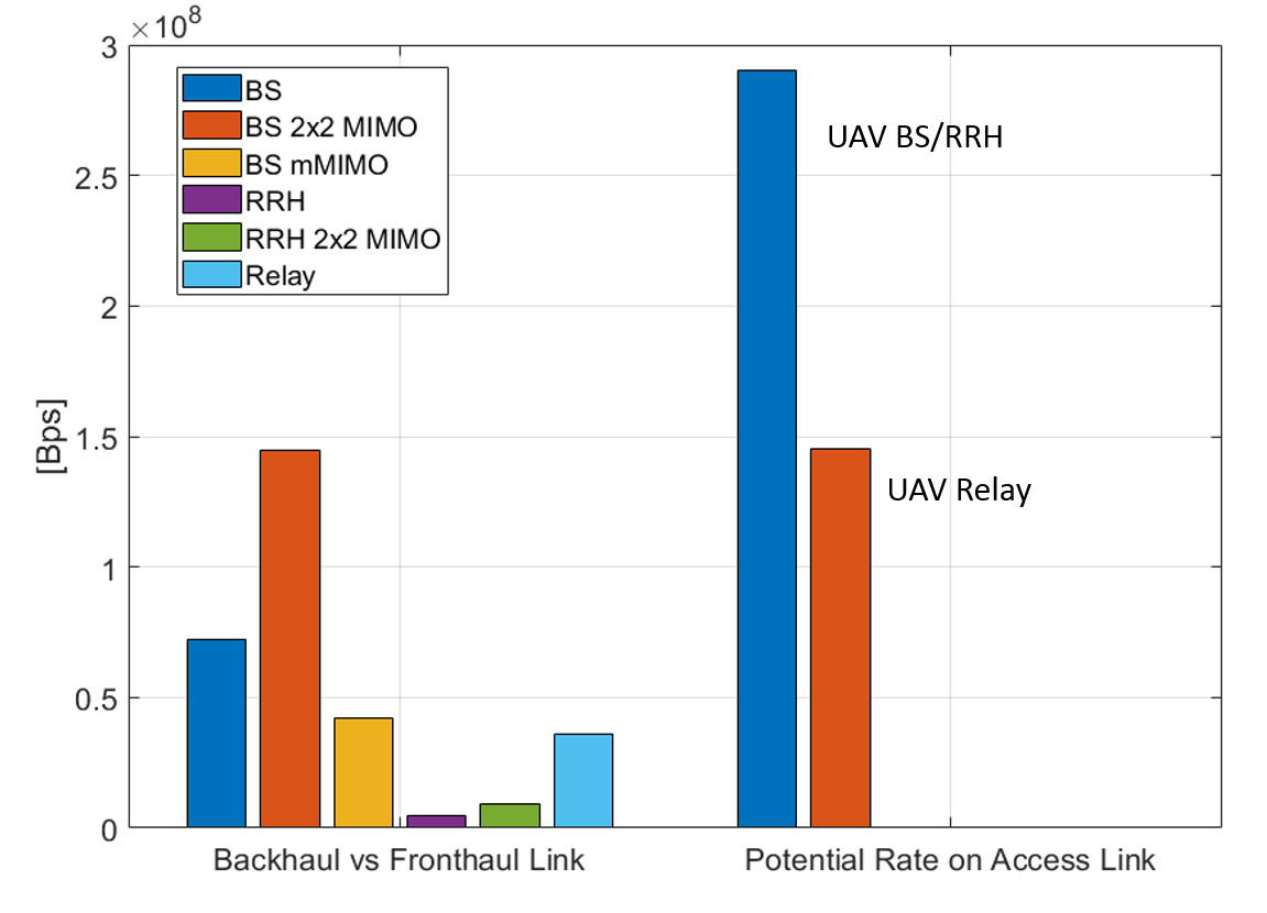
Figure 3 shows the simulation latency results for different numbers of users. As expected, due to the lower computation time on the UAV, the RRH and the Relay configuration give significant benefits in term of latency in respect to the BS configuration.
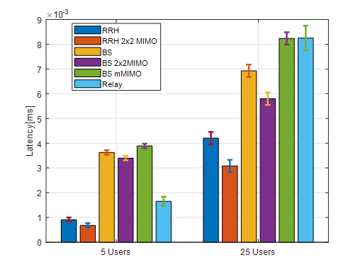
These results emphasizes the fact that implementing a UAV-aided wireless network over the sea struggle with issues at different levels. Different evaluation parameters lead to opposite results. For this reason an optimal solution is hard to design, but, considering different performance indicators it is possible to choose the best combination of BH technology and system architecture.
V Conclusion
In this paper we focused on the problem of providing cellular connectivity to offshore areas for search and rescue operations. We have presented three different system architectures and highlighted the main benefits and challenges. To evaluate the proposed architectures, we have compared their performance in term of data rate, latency and energy efficiency. Results shows the need of a cost function to evaluate the best architecture based on an assigned priority.
Acknowledgment
This material is based upon works supported by the Irish Research Council under Grant GOIPG/2017/1741.
- 5G
- Fifth Generation
- ACO
- Ant Colony Optimization
- BB
- Base Band
- BBU
- Base Band Unit
- BER
- Bit Error Rate
- BH
- Backhaul
- BS
- Base Station
- BW
- bandwidth
- C-RAN
- Cloud Radio Access Networks
- CAPEX
- Capital Expenditure
- CoMP
- Coordinated Multipoint
- CPRI
- Common Public Radio Interface
- DAC
- Digital-to-Analog Converter
- DAS
- Distributed Antenna Systems
- DBA
- Dynamic Bandwidth Allocation
- DL
- Downlink
- FBMC
- Filterbank Multicarrier
- FEC
- Forward Error Correction
- FH
- Fronthaul
- FFR
- Fractional Frequency Reuse
- FSO
- Free Space Optics
- GS
- Ground Station
- GSM
- Global System for Mobile Communications
- HAP
- High Altitude Platform
- HL
- Higher Layer
- HARQ
- Hybrid-Automatic Repeat Request
- KPI
- Key Performance Indicator
- IoT
- Internet of Things
- LAN
- Local Area Network
- LAP
- Low Altitude Platform
- LL
- Lower Layer
- LOS
- Line of Sight
- LTE
- Long Term Evolution
- LTE-A
- Long Term Evolution Advanced
- MAC
- Medium Access Control
- MAP
- Medium Altitude Platform
- ML
- Medium Layer
- MME
- Mobility Management Entity
- mmWave
- millimeter Wave
- MIMO
- Multiple Input Multiple Output
- NFP
- Network Flying Platform
- NFPs
- Network Flying Platforms
- NLOS
- Non Line of Sight
- OFDM
- Orthogonal Frequency Division Multiplexing
- PAM
- Pulse Amplitude Modulation
- PAPR
- Peak-to-Average Power Ratio
- PGW
- Packet Gateway
- PHY
- physical layer
- PSO
- Particle Swarm Optimization
- PTP
- Poin to Point
- QAM
- Quadrature Amplitude Modulation
- QoE
- Quality of Experience
- QoS
- Quality of Service
- QPSK
- Quadrature Phase Shift Keying
- RF
- Radio Frequency
- RN
- Remote Node
- RAU
- Remote Access Unit
- RAN
- Radio Access Network
- RRH
- Remote Radio Head
- RRC
- Radio Resource Control
- RRU
- Remote Radio Unit
- RSRP
- Reference Signals Received Power
- SCBS
- Small Cell Base Station
- SDN
- Software Defined Network
- SNR
- Signal-to-Noise Ratio
- SON
- Self-organising Network
- TETRA
- Trans-European Trunked Radio
- TDD
- Time Division Duplex
- TD-LTE
- Time Division LTE
- TDM
- Time Division Multiplexing
- TDMA
- Time Division Multiple Access
- UE
- User Equipment
- UAV
- Unmanned Aerial Vehicle
References
- [1] E. Cusumano, “Emptying the sea with a spoon? Non-governmental providers of migrants search and rescue in the mediterranean,” Marine Policy, vol. 75, pp. 91 – 98, 2017. [Online]. Available: http://www.sciencedirect.com/science/article/pii/S0308597X16304821
- [2] G. Fontanesi, A. Zhu, and H. Ahmadi, “Saving lives at sea with uav-assisted wireless networks,” in 2018 IEEE 29th Annual International Symposium on Personal, Indoor and Mobile Radio Communications (PIMRC), Sep. 2018, pp. 1–2.
- [3] Y. Zeng, R. Zhang, and T. J. Lim, “Wireless communications with unmanned aerial vehicles: opportunities and challenges,” IEEE Commun. Mag., vol. 54, no. 5, pp. 36–42, May 2016.
- [4] S. O. Murphy, K. N. Brown, and C. Sreenan, “Demo: Cellphone localisation using an autonomous unmanned aerial vehicle and software defined radio,” in Proceedings of the 2017 International Conference on Embedded Wireless Systems and Networks. Junction Publishing, 2017, pp. 254–255.
- [5] A. Ranjan, B. Panigrahi, H. B. Sahu, and P. Misra, “Skyhelp: Leveraging uavs for emergency communication support in deep open pit mines,” in 2018 10th International Conference on Communication Systems Networks (COMSNETS), Jan 2018, pp. 546–548.
- [6] N. Zhao, W. Lu, M. Sheng, Y. Chen, J. Tang, F. R. Yu, and K. Wong, “Uav-assisted emergency networks in disasters,” IEEE Wireless Communications, vol. 26, no. 1, pp. 45–51, February 2019.
- [7] H. Ahmadi, K. Katzis, and M. Z. Shakir, “A novel airborne self-organising architecture for 5G+ networks,” in IEEE VTC17-Fall, Sept 2017, pp. 1–5.
- [8] M. A. Marotta, H. Ahmadi, J. Rochol, L. DaSilva, and C. B. Both, “Characterizing the relation between processing power and distance between bbu and rrh in a cloud ran,” IEEE Wireless Communications Letters, vol. 7, no. 3, pp. 472–475, June 2018.
- [9] Z. Becvar, M. Vondra, P. Mach, J. Plachy, and D. Gesbert, “Performance of mobile networks with uavs: Can flying base stations substitute ultra-dense small cells?” in European Wireless 2017; 23th European Wireless Conference, May 2017, pp. 1–7.
- [10] I. A. Alimi, A. L. Teixeira, and P. P. Monteiro, “Toward an efficient c-ran optical fronthaul for the future networks: A tutorial on technologies, requirements, challenges, and solutions,” IEEE Communications Surveys Tutorials, vol. 20, no. 1, pp. 708–769, Firstquarter 2018.
- [11] M. Chen, M. Mozaffari, W. Saad, C. Yin, M. Debbah, and C. S. Hong, “Caching in the sky: Proactive deployment of cache-enabled unmanned aerial vehicles for optimized quality-of-experience,” IEEE Journal on Selected Areas in Communications, vol. 35, no. 5, pp. 1046–1061, May 2017.
- [12] L. Chiaraviglio, N. Blefari-Melazzi, W. Liu, J. A. Gutierrez, J. van de Beek, R. Birke, L. Chen, F. Idzikowski, D. Kilper, P. Monti, A. Bagula, and J. Wu, “Bringing 5g into rural and low-income areas: Is it feasible?” IEEE Communications Standards Magazine, vol. 1, no. 3, pp. 50–57, SEPTEMBER 2017.
- [13] T. S. Rappaport, Y. Xing, G. R. MacCartney, A. F. Molisch, E. Mellios, and J. Zhang, “Overview of millimeter wave communications for fifth-generation (5g) wireless networks—with a focus on propagation models,” IEEE Transactions on Antennas and Propagation, vol. 65, no. 12, pp. 6213–6230, Dec 2017.
- [14] C. Zhang, W. Zhang, W. Wang, L. Yang, and W. Zhang, “Research challenges and opportunities of uav millimeter-wave communications,” IEEE Wireless Communications, vol. 26, no. 1, pp. 58–62, February 2019.
- [15] A. Al-Hourani, S. Kandeepan, and A. Jamalipour, “Modeling air-to-ground path loss for low altitude platforms in urban environments,” in 2014 IEEE Global Communications Conference, Dec 2014, pp. 2898–2904.
- [16] A. Fotouhi, H. Qiang, M. Ding, M. Hassan, L. G. Giordano, A. Garcia-Rodriguez, and J. Yuan, “Survey on uav cellular communications: Practical aspects, standardization advancements, regulation, and security challenges,” IEEE Communications Surveys Tutorials, pp. 1–1, 2019.